Agilent Technologies AssayMAP Bravo Скачать руководство пользователя страница 89

81

Verifying the installation and setup

About installing the Bravo pendant, Light Curtain, and shields

 AssayMAP Bravo Platform Installation Guide

Figure 

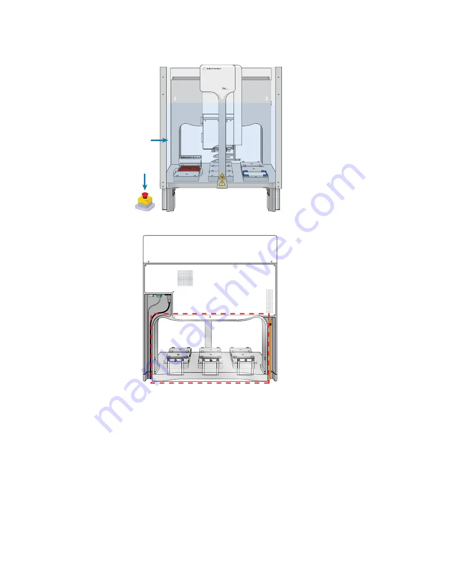
AssayMAP Bravo Platform with Light Curtain and emergency-stop pendant

Figure 

Bravo rear shield with access window covers installed

00220

Bravo

Back

20c

Содержание AssayMAP Bravo

Страница 1: ...AssayMAP Bravo Platform Installation Guide Original Instructions...

Страница 2: ...user have a separate written agreement with warranty terms covering the material in this document that conflict with these terms the warranty terms in the sep arate agreement shall control Technology...

Страница 3: ...About verifying the deck configuration in the profile 43 Verifying the Autofill Station configuration 96AM Wash Station 45 Verifying the Peltier Thermal Station configuration 47 Verifying the Orbital...

Страница 4: ...ayMAP Bravo Platform Installation Guide Workflow for setting teachpoints in each profile manually 100 Adjusting the teachpoint for the Bravo Plate Riser 101 Adjusting the teachpoint for the red PCR pl...

Страница 5: ...1 AssayMAP Bravo Platform Installation Guide 1 Before you start About this guide on page 2 Related guides and where to find them on page 2 Service documentation on page 4 Safety information on page 4...

Страница 6: ...can find the following checklists on the Agilent AssayMAP Bravo Platform product page at https www agilent com en products automation solutions protein sample preparation assaymap bravo platform Site...

Страница 7: ...ample Prep Workbench Pump Module User Guide Setting up the Pump Module and the autofilling reservoirs and wash stations VWorks Knowledge Base and Protein Sample Prep Workbench AssayMAP Bravo Platform...

Страница 8: ...hem agilent com sites partners support default aspx Safety information Before installing and using the Bravo Platform make sure you are aware of the potential hazards and understand how to avoid being...

Страница 9: ...ments on page 3 Installation workflow for standard configuration on page 4 Installing the Bravo risers on page 5 Installing the 96AM Wash Station and Pump Module on page 10 Installing the standard pla...

Страница 10: ...ravo Platform which is required for running the AssayMAP protocols Figure AssayMAP Bravo Platform components Item Required hardware 1 Gripper upgrade 2 Bravo 96AM Head 3 96AM Wash Station 4 Pump Modul...

Страница 11: ...ain and the emergency stop pendant shown in the following figures Computer workstation Figure Standard configuration with Light Curtain Figure Emergency stop pendant Computer requirements The software...

Страница 12: ...s on page 5 5 Connect the Bravo Platform power cord communications cable and pendant cable Bravo Platform Safety and Installation Guide 6 Install the Bravo 96AM Head About installing the AssayMAP head...

Страница 13: ...lb Attempting to move the Bravo device without assistance could cause personal injury Request assistance and use proper lifting techniques when moving the Bravo device CAUTION Tugging on the tie bar o...

Страница 14: ...ve the four rubber feet from the base of the Bravo deck Figure Bottom view of Bravo deck 4 On the bottom of the Bravo deck install the two risers one on each side Use the four screws and washers provi...

Страница 15: ...g proper lifting techniques Figure Bravo Platform on risers with no deck platepads Ensure that the instrument and riser assembly does not wobble and that it sits flat on the table If the Bravo Platfor...

Страница 16: ...tall the head The Bravo 96AM Head has four retractable tip box stripper pins two on each side of the probes as the following figure shows Before you install the Bravo 96AM Head ensure that the tip box...

Страница 17: ...the pin stop Verify that the pin is properly seated If the pin has an arrow the square end of the arrow should disappear or be barely visible IMPORTANT If the pin hits a stop before it retracts compl...

Страница 18: ...nstalled on platepad with brackets Before you start Use the following workflow Step For this task See 1 Ensure that the wash station chimneys are in good condition Wash station inspection on page 11 2...

Страница 19: ...s are fully seated in the wash station their height should be consistent less than 1 mm difference in height If any chimney is taller than the others use your thumb to press down on the chimney so tha...

Страница 20: ...sure that you install the 96AM Wash Station at deck location 1 Figure 96AM Wash Station installed at deck location 1 To install the wash station 1 At deck location 1 remove the standard platepad if in...

Страница 21: ...rs 3 Install the wash station on the platepad as follows a Ensuring that the inlet and outlet ports are towards the rear of the deck place the wash station on the platepad b Guide the platepad s inner...

Страница 22: ...he 96AM Wash Station As the figure shows the upper pump A is for the fill line and the lower pump B is for the empty line Note You specify which pump is for filling and which pump is for emptying in B...

Страница 23: ...rom the source bottle to the wash station and empty line tubing connections on either side of the 5 16 in diameter tubing Note The 5 16 in diameter tubing is too large for the quick disconnect fitting...

Страница 24: ...ch of the three barbed ends of a 1 4 inch 3 way connector a b Attach the two free ends of the prepared 3 way tubing assembly to the wash station outlet ports as the following figure b shows c Repeat s...

Страница 25: ...any creeping of the tubing occurs during operation tighten the clamps slightly using the clamp dials 4 For the bottom pump a Prepare an approximately 20 32 to 25 4 cm 8 to 10 inch length of 5 16 inch...

Страница 26: ...nes from the Pump Module to the corresponding lines on the wash station 6 Connect the tubing from the Pump Module to the source and waste carboys as follows a Cut a length of the 1 4 inch tubing measu...

Страница 27: ...t the Pump Module RJ 45 cable to the Pump I O port 1 as the following figure shows Connect the other end of the cable to the COM IN port 2 on the rear of the Pump Module 2 Connect the Pump Module powe...

Страница 28: ...Before you start Make sure you have the following Platepad Flathead cap screw M6 x 40 mm Procedure To install a platepad 1 With the crosshairs toward the back side of the device align the pins in the...

Страница 29: ...e following figure shows the assembled Peltier Thermal Station with the custom plate nest Figure Assembled Peltier Thermal Station with custom plate nest Before you start Ensure you have the following...

Страница 30: ...tall the platepad if applicable from deck location 4 To uninstall a platepad remove the M6 flathead screw from the center of the platepad Remove the platepad from the deck 2 Remove the cutout cover Us...

Страница 31: ...stic interface on the top of the Peltier Thermal Station assembly Figure Peltier Thermal Station assembly with plastic interface removed 4 Perform the following steps to place the Peltier Thermal Stat...

Страница 32: ...surface e If there is slight resistance when fitting the assembly into the cutout or when positioning the bracket you may use a rubber mallet to tap the metallic base or bracket into place Figure Tapp...

Страница 33: ...l Station as follows a Orient the plate nest so that the crosshairs is towards the back of the deck b Position the plate nest and ensure that it is fully seated c Install the M3 screw in the center of...

Страница 34: ...1 Connect the STC Controller to the computer using the provided USB cable 2 Connect the STC Controller power cable to an AC outlet 3 Set the controller power switch to the On position Installing and...

Страница 35: ...ocedure to install the Orbital Shaking Station at deck location 9 Ensure that no platepad is installed at deck location 9 If necessary uninstall the platepad by removing the M6 screw in the center of...

Страница 36: ...re the feet on the bottom of the Orbital Shaking Station are pressed evenly into the adapter pad and the station remains level Note The feet of the Orbital Shaking Station are compressible and these s...

Страница 37: ...g a USB to serial adapter If a serial port is not available use a USB to serial adapter 3 On the control module ensure that the knob is turned fully counterclockwise so that the red arrow 3 is pointin...

Страница 38: ...ollowing procedure for instructions The computer auto assigns the COM port for the connection which may be different than the COM port specified in the AssayMAP profiles To resolve conflicts you may d...

Страница 39: ...Verifying the profile settings and configuration on page 39 About verifying the deck configuration in the profile on page 43 Verifying the Autofill Station configuration 96AM Wash Station on page 45 V...

Страница 40: ...oft Excel is required for the Protein Sample Prep Workbench calculators Agilent Technologies does not supply Microsoft Excel Turning on the instrument To turn on the AssayMAP Bravo Platform 1 Ensure t...

Страница 41: ...computer LAN 1 From the Windows desktop go to Control Panel Network and Sharing Center 2 In the Network and Sharing Center window locate and click Sub Network or Local Area Connection as applicable N...

Страница 42: ...ote The name of the Ethernet adapter can vary depending on the computer model 5 In the Internet Protocol Version 4 TCP IPv4 dialog box a Select Use the following IP address b In the IP address boxes t...

Страница 43: ...y for fully qualified and trained Agilent service engineers To open Windows Regedit go to Start type regedit in the search box and press ENTER When the Registry Editor window opens locate the Velocity...

Страница 44: ...1 Ensure that you have the latest Protein Sample Prep Workbench installer The installer is included on a CD as a part of the AssayMAP Bravo Platform bill of material BOM 2 Run the Protein Sample Prep...

Страница 45: ...that the Inheco STC Controller and the control module for the Orbital Shaking Station are turned on 2 Turn on the computer and start the Microsoft Windows operating system 3 On the side of the AssayMA...

Страница 46: ...y the correct deck configuration and the associated teachpoints for the Bravo deck layout IMPORTANT If other liquid handling heads will be used on the AssayMAP Bravo Platform such as a 96LT Head ensur...

Страница 47: ...rt menu on the Windows desktop to start the VWorks software 2 Ensure that Simulation is off Figure Simulation button in the VWorks window 3 In the VWorks window open the corresponding AssayMAP device...

Страница 48: ...ravo dev tab and Profile setting for AssayMAP 1 6 In the name dev tab click Device diagnostics The Bravo Diagnostics dialog opens 7 In the Profiles tab verify the Profile name 8 Verify the following H...

Страница 49: ...is connected via ethernet and then click Find available device to select the device to associate with the profile In the Discovered BioNet Devices dialog box that appears perform the following tasks...

Страница 50: ...ddress to identify the Bravo device for this profile To successfully communicate with the Bravo device the Status column must display New or Matched c Click OK 10 In the Miscellaneous area verify the...

Страница 51: ...figure the corresponding deck locations for these accessories in the AssayMAP 1 profile Verifying the Autofill Station configuration 96AM Wash Station on page 45 GlykoPrep Plus profile By default the...

Страница 52: ...lidding and Relidding tasks Verifying the Autofill Station configuration 96AM Wash Station on page 45 Verifying the Peltier Thermal Station configuration on page 47 Verifying the Orbital Shaking Stati...

Страница 53: ...uration in a profile 1 In Bravo Diagnostics ensure the correct profile is selected in the Profiles tab 2 In the Configuration tab verify that the deck image shows a Pump Module at deck location 1 Note...

Страница 54: ...nd then click Next 7 Click Finish The Bravo Accessories Wizard closes 8 If you made any changes to the configuration settings click the Profiles tab and then click Update this profile to save the chan...

Страница 55: ...ofile To verify the Peltier Thermal Station configuration in a profile 1 In Bravo Diagnostics ensure the correct profile is selected in the Profiles tab 2 In the Configuration tab verify that the deck...

Страница 56: ...oller ships with an MTCSTC Id setting of 0 However this setting may have been changed on demo units for use with multiple devices Use the DIP switches on the back of the STC Controller to determine wh...

Страница 57: ...ofile To verify the Orbital Shaking Station configuration in a profile 1 In Bravo Diagnostics ensure the correct profile is selected in the Profiles tab 2 In the Configuration tab verify that the deck...

Страница 58: ...ed to the computer You might need to lookup the port assigned to this device in the Windows Device Manager Note Occasionally a port number is reassigned for a USB to serial connection if you disconnec...

Страница 59: ...Initializing the profile in Bravo Diagnostics To initialize the profile 1 In the Profiles tab ensure that the correct profile is selected and then click Initialize this profile to start initializing...

Страница 60: ...re you perform the following workflow Step Task See 1 Initialize the AssayMAP 1 profile Initializing the profile in Bravo Diagnostics on page 51 2 Test the communication with the accessories Procedure...

Страница 61: ...utility which will test the functioning of the Pump Module and wash station using liquid To test the communication with the Pump Module 1 Ensure that the Pump Module is on 2 Lift the flip top cover o...

Страница 62: ...latform Installation Guide 4 Click Run pumps 5 Verify that the pumps run While they are running verify that the pumps are spinning in the correct directions Top pump should be spinning clockwise Botto...

Страница 63: ...ics dialog box opens 3 In the Bravo Accessory Diagnostics dialog box verify that the correct device CPAC Ultraflat appears in the display at the top 4 In the Heat area set the parameters to test the t...

Страница 64: ...n and then click Diagnose accessory The Bravo Accessory Diagnostics dialog box opens 2 Type the RPM select the Stir direction and then click Start 3 At the Orbital Shaking Station on the deck verify t...

Страница 65: ...ints Teaching part 1 Setting teachpoints in AssayMAP 1 profile on page 58 Teaching part 2 Adjusting teachpoints for accessories on page 62 Teaching part 3 Updating the other profiles based on AssayMAP...

Страница 66: ...are from the deck except for the 96AM Wash Station at deck location 1 The wash station remains installed at deck location 1 in the following procedure while you set the teachpoint for deck location 2...

Страница 67: ...remaining teachpoints To set the teachpoints 1 Manually seat a 250 L pipette tip on probe A1 back left corner of the Bravo 96AM Head Ensure that the pipette tip locks into place with the probe Ensure...

Страница 68: ...oves down along the z axis towards the crosshairs the following error message appears Visually inspect the clearance remaining between the tip and the crosshairs If the tip is not yet at the crosshair...

Страница 69: ...Approach height above teachpoint list select 10 and then click Approach The Bravo head moves to deck location 3 and moves down so that the pipette tip is approximately 10 mm above the platepad crossha...

Страница 70: ...late that fits in the plate nest of an accessory The teaching plate has a crosshairs in one corner as the following figure shows Figure Pipettor teaching plate 250 L pipette tip seated on probe A1 bac...

Страница 71: ...rements until you reach the lowest possible height that allows the feeler gauge to slide under the pipette tip without deflecting it Note Alternatively you may use the Jog Axes controls to move the he...

Страница 72: ...ed them in this profile 3 In the Location list locate the Z axis box Write down the Z axis value on a piece of paper You will use this value in a subsequent step Note The Z axis teachpoint value for d...

Страница 73: ...tops of the chimneys 6 When the probes and chimneys are perfectly aligned use the Jog Axes controls to move the head down slowly along the z axis to the original Z axis teachpoint value that you reco...

Страница 74: ...no pipette tips or cartridges are seated on the Bravo 96AM Head Ensure that the 250 L tip remains selected as the Teaching tip type in the Profiles tab To adjust the teachpoint for the Cartridge Tip S...

Страница 75: ...the Cartridge Tip Seating Station from the deck 10 Carefully use the Down Z control to jog the head down incrementally until the value in the Z axis box matches the value that you noted in step 3 11...

Страница 76: ...ce Workbench Protocols AssayMAP Teachpoint Update v1p0 pro 250 L pipette tip IMPORTANT Ensure that the pipette tip is new and in good condition Note The AssayMAP Teachpoint Update protocol is not desi...

Страница 77: ...col Files pro Locate the C VWorks Workspace Workbench Protocols folder select the AssayMAP Teachpoint Update v1p0 pro file and then click Open 3 When the following VWorks initialization message appear...

Страница 78: ...sayMAP 1 70 AssayMAP Bravo Platform Installation Guide 5 In the Run Configuration dialog box click Finish to start the protocol 6 When the Update Teachpoints dialog box appears click Continue update t...

Страница 79: ...tform Installation Guide 7 When the WARNING dialog box appears click Continue to update the teachpoints in all the Workbench profiles based on the AssayMAP 1 profile teachpoints IMPORTANT After the pr...

Страница 80: ...place on the gripper fingers and in good condition Ensure the gripper pads are not partially ripped off or pulled askew Use the following workflow Adjusting the gripper y axis offset Use deck location...

Страница 81: ...n the deck image click a deck location where a standard platepad is installed The location should be easily accessible for example in the front row or a corner 4 Click Move to move the gripper to the...

Страница 82: ...owing to adjust the clearance a Click the Jog Teach tab and ensure that the deck location you selected in step 3 is still selected b Under Jog Axes set the Back Y Forward Y increment to a small enough...

Страница 83: ...ent to 0 2 mm and then use the Back Y and Forward Y buttons to position the gripper so that the fingers are at equal distances around the platepad Ensure the pair of gripper pads on each side are as c...

Страница 84: ...icroplate for this test for example 96 Greiner 650201 U Bottom Standard PolyPro To test the gripper pick and place operations 1 Place a microplate on a platepad at the deck location where you are star...

Страница 85: ...olds the microplate securely and keeps it level while moving the microplate from location to location If the gripper performs the operation without problem no further adjustment is required If the gri...

Страница 86: ...Setting the teachpoints Checking and adjusting the gripper offset 78 AssayMAP Bravo Platform Installation Guide...

Страница 87: ...ight Curtain and shields on page 80 Opening the Workbench and accessing the utilities on page 82 Running the Startup utility on page 83 Testing the safety equipment on page 84 Washing the syringes to...

Страница 88: ...through the access windows in the side and rear shields Step For this task See 1 Ensure that the Light Curtain pendant and shields are installed About installing the Bravo pendant Light Curtain and s...

Страница 89: ...lling the Bravo pendant Light Curtain and shields AssayMAP Bravo Platform Installation Guide Figure AssayMAP Bravo Platform with Light Curtain and emergency stop pendant Figure Bravo rear shield with...

Страница 90: ...Sample Prep Workbench icon Alternatively on the Windows desktop click Start Agilent Technologies Protein Sample Prep Workbench Accessing a workbench utility To access a utility 1 In the Protein Sample...

Страница 91: ...le Prep Workbench 3 Click Instructions to display the user guide for the corresponding utility Running the Startup utility The Startup utility initializes the AssayMAP Bravo Platform and primes the wa...

Страница 92: ...interrupting the Light Curtain trips the interlock circuit causing the motion of the Bravo head to stop Troubleshooting problems Probable cause and solution Fluid does not flow out of a chimney A trap...

Страница 93: ...ation Settings area specify the following settings for the run 3 Click Run Cartridge Transfer to start the run 4 As soon as the Bravo head starts to move away from its position above the wash station...

Страница 94: ...ops moving and an error message appears 8 To recover from the emergency stop a Ensure that no objects are in the path of the Light Curtain b In the AssayMAP Bravo Error dialog box click Abort to end t...

Страница 95: ...filled labware on Bravo deck location 4 2 Ensure that the deck is clear of other labware except the wash station at deck location 1 and the 96AM Cartridge Tip Seating Station at deck location 2 Make...

Страница 96: ...d in this configuration Leave the labware selections at the default setting for these locations Do not place labware on the deck at these locations 5 Under Wash Settings set the following 6 For Wash 1...

Страница 97: ...for first time use AssayMAP Bravo Platform Installation Guide 8 Click Wash Syringes 9 After the protocol finishes leave everything in place and click Wash Syringes again 10 After the protocol finishe...

Страница 98: ...ce cartridge rack 96AM Cartridge Rack and Receiver Plate to the destination cartridge rack Cartridge Tip Seating Station Before you start Make sure the Bravo deck is set up as follows The empty Cartri...

Страница 99: ...ng a mock run AssayMAP Bravo Platform Installation Guide Figure Cartridge Tip Seating Station and Cartridge Rack with Receiver Plate To transfer the cartridges 1 Open the Utility Library locate the Ca...

Страница 100: ...the Affinity Purification protocol IMPORTANT For this mock run you will not use any additional labware Ensure that the only items on the deck are the 96AM Wash Station at deck location 1 and the Cartr...

Страница 101: ...re Defaults to ensure that the settings are correct 3 Under Application Settings change the following settings as shown in the following figure a Set the Number of Full Columns of Cartridges to 12 b S...

Страница 102: ...should take less than 15 minutes to complete 6 During the mock run observe the automation movements of the Bravo 96AM Head to assess whether any problems occur Make a note of any problems See the fol...

Страница 103: ...ges in the seating station 1 Washes the syringes at the wash station Equilibrate 3 Aspirates the Equilibration Buffer 2 Mounts the cartridges on the head 1 Dispenses the Equilibration Buffer through t...

Страница 104: ...ation Internal Cartridge Wash 2 6 Aspirates the Cartridge Wash Buffer 2 into the syringes 2 Mounts the cartridges on the head 1 Dispenses the Cartridge Wash Buffer 2 through the cartridges for the Int...

Страница 105: ...ges and then rerun the Syringe Test to confirm all the syringes are functioning properly Item Required items Description Part number 1 Syringe Test Kit Contains materials and reagents to perform 20 te...

Страница 106: ...ice overnight The Shutdown utility prepares the AssayMAP Bravo Platform for idle time by Washing the syringes the specified number of wash cycles Aspirating 200 L of Syringe Storage Liquid into the sy...

Страница 107: ...achpoints in each profile This appendix contains the following topics Workflow for setting teachpoints in each profile manually on page 100 Adjusting the teachpoint for the Bravo Plate Riser on page 1...

Страница 108: ...e teachpoints associated with each profile for your specific instrument and Bravo 96AM Head Step For this task See 1 Initialize the AssayMAP 1 profile Initializing the profile that you are verifying o...

Страница 109: ...o Plate Riser About the AssayMAP Normalization profile The AssayMAP Normalization profile Normalization AM Bravo dev includes teachpoints for the Bravo Plate Riser at deck locations 2 and 6 However yo...

Страница 110: ...he Approach height above teachpoint box type 50 and then click Approach The Bravo head moves to the selected deck location and then moves down so that the tip is approximately 22 mm above the crosshai...

Страница 111: ...lignment to ensure that the tip is centered from left to right and front to back Adjusting the teachpoint for the red PCR plate insert About this topic Use the following procedure only if the deck con...

Страница 112: ...b click Location 4 2 Click Move to move the head to the previously defined teachpoint for location 4 3 Using the Jog Axes controls jog the head up Z by exactly 4 4 mm For example if the value for the...

Страница 113: ......

Страница 114: ...Agilent Technologies Installation Guide G5571 90001 Revision B March 2018...

Отзывы: