


L3447
Emax DC
3/108
Doc. No.
Model
Apparatus
Scale
Page No.
1SDH000635R0002
L3728
14.3
PR120/K - SIGNALLING module .......................
page
81
14.3.1
General characteristics ............................................. « 81
14.3.2
Front view .................................................................. « 81
14.3.3
Releases complete with the module ......................... « 81
14.3.4
Characteristics of the digital input ............................ « 81
14.3.5
Characteristics of the signalling contacts ................. « 81
14.3.6
Power supply ............................................................ « 82
14.3.7
PR120/K module menu ............................................. « 82
14.3.8
Configurable input .................................................... « 82
14.3.8.1
Input configuration settings ...................................... « 82
14.3.8.2
Input function settings (ACTION) ............................. « 82
14.3.8.3
Setting the input enabling delay .............................. « 82
14.3.9
PR120/K module menu layout .................................. « 83
14.4
PR120/DC - override protection module .................. « 84
14.4.1
General characteristics ............................................. « 84
15
Appendices ......................................................
« 85
15.1
PR021/K outside signalling unit ................................. « 85
15.1.1
General information ................................................... « 85
15.1.2
Power supply ............................................................ « 85
15.1.3
General characteristics of the signalling relays ........ « 85
15.1.4
Relay functions .......................................................... « 85
15.1.5
PR021/K signalling unit menu ................................... « 85
15.1.5.1
PR021/K unit menu table .......................................... « 85
15.1.5.2
Important note ........................................................... « 86
15.2
Data Logger (recorder) ........................................... « 87
15.2.1
General characteristics ............................................. « 87
15.2.2
Description of the Data Logger menu ...................... « 87
15.2.2.1
Enabling the Data Logger ........................................ « 87
15.2.2.2
Setting the sampling frequency ............................... « 87
15.2.2.3
Setting the standard stop events (triggers) ............. « 87
15.2.2.4
Setting and viewing customized stop events
(triggers) ................................................................... « 87
15.2.2.5
Setting the stopping delay ....................................... « 88
15.2.2.6
Restart/Stop Data Logger ........................................ « 88
15.2.3
Recording time windows .......................................... « 88
15.2.4
Description of the information given by the Data
Logger system .......................................................... « 89
15.2.4.1
Combination of devices for reading/setting data
from the Data Logger system ................................... « 89
15.2.4.2
Access to the saved data from the system .............. « 89
15.2.4.3
Information from the system on the configuration
and status of the Data Logger .................................. « 90
15.2.5
Data Logger commands from the systems ............. « 90
15.3
Table showing lists of events ..................................... « 91
15.3.1
"Standard" events for PR120/K and for PR021/K
selectable from the relay .......................................... « 91
15.3.2
Examples of "Custom" events for the Data Logger
function for PR120/K and PR021/K .......................... « 91
15.3.3
"Standard" events for the Data Logger function
selectable from the relay .......................................... « 91
15.3.4
Combining the devices needed to customize
settings ...................................................................... « 91
16.
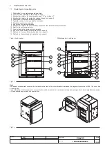
Overall dimensions .................................................... « 92
17.
Circuit diagrams ........................................................ « 101