L3447
Emax DC
34/108
L3728
Model
Scale
Page No.
Doc. No.
Apparatus
1SDH000635R0002
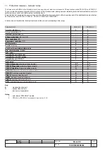
12.2.9.6
Load control function
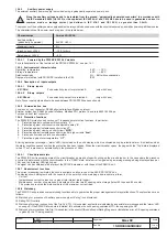
Single loads can be enabled/disabled on the load side before the overload protection L intervenes and trips the circuit-breaker on the supply
side. This is done by contactors or switch-disconnectors (wired outside the release), controlled by the PR122/DC by means of contacts on the
PR120/K module or on the PR021/K external unit.
The current thresholds are lower than those available with the protection L, so that the load control can be used to prevent tripping due to overloads.
The function is active when an auxiliary power supply is present, or supply from PR120/V (see par. 14.1.3)
The operating logic involves the activation of three contacts when the preset thresholds LC1, LC2 and I
w
are exceeded.
Thresholds LC1 and LC2 are expressed as a percentage of I
1
(current threshold specified for protection L) while the "warning current" I
w
is expressed
as an absolute value. The allowable values are given in the following table:
Warning current Iw
0.30 ÷ 10.0 step 0.05xIn
Threshold LC1
50% ÷ 100% step 1% xI
1
Threshold LC2
50% ÷ 100% step 1% xI
1
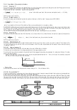
From the PR122/DC you can associate each of the PR120/K or PR121/K contacts with a configuration (NO or NC), a delay and the eventual latch.
L
curve
0,4xIn
≤
I
1
≤
1xIn
3 s
≤
t
1
≤
102s
(1)
, step 3 s
Release between
± 10%, I
g
≤
4In
IEC 60255-8
step 0,01xIn
t1@ 3I
1
1,05 and1,2 xI1
± 20%, I
g
>
4In
S
0,6 xIn
≤
I
2
≤
10xIn
0,05 s
≤
t
2
≤
0,35 s, step 0,01s
±7%,I
g
≤
6 In
The best of the two data
(t=k)
step 0,1xIn
0,10 s
≤
t
2 start-up
≤
30 s, step 0,01s
±10%,I
g
>
6 In
± 10% o 40 ms
0,6 xIn
≤
I
2 start-up
≤
10xIn 0,04 s
≤
t
2 sel
≤
0,20 s, step 0,01s
step 0,1xIn
S
0,6xIn
≤
I
2
≤
10xIn
0,05 s
≤
t
2
≤
0,35 s,
± 7%,I
g
≤
6 In
± 15%, I
g
≤
4In
(t=k/i
2
)
step 0,1xIn
step 0,01 s at 10xIn
± 10%,I
g
>
6 In
± 20%, I
g
>
4In
I
1,5xIn
≤
I
3
≤
10xIn
≤
30 ms
(t=k)
step 0,1xIn
0,10 s
≤
t
2 start-up
≤
30 s, step 0,01 s
± 10%
where I>I4
MCR
6.0xIn
≤
I
5
≤
10xIn
≤
30 ms
(3)
± 10%
(t=k)
step 0.1xIn
OT
Fixed, defined by
Instantaneous
± 5°C
- - -
(temp=k)
SACE
Iinst
Automatic, defined
Instantaneous
by SACE
LC1/LC2 loads
50%
÷
100% step 0,05xI
1
control
Warning Iw
0,3
÷
10I
n
step 0,05xI
n
± 10%
10
÷
40 ms
Protection
Disabling
Disabling of
TRIP only
Zone selectivity
Start-up threshold
Thermal memory
Trip Threshold
Trip time
tolerance
(2)
Trip Time
Trip
threshold
tolerance
(2)
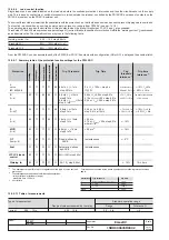
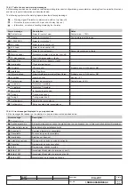
12.2.9.7 Summary table of the protection function settings for the PR122/DC
(1)
The minimum value of this trip is 1s regardless of the type of curve set (self-
protection).
(2)
These tolerances are based on the following assumptions:
- relay at full power (without start-up)
- preset trip time
≥
100 ms.
(3)
no-trip time
For all cases not covered by the above hypotheses, the following tolerance values
apply:
Protections
Trip threshold
Trip time
L
Release between 1,05 e 1,25 x I1
± 20%
S
± 10%
± 20%
I
± 15%
≤
60ms
Others
± 20%
12.2.9.7.1 Table of measurements
Type of measurement
Standard operation range
Range of values measured by the relay
Range
Tolerance %
Current
0,05 ... 12 In
0,05 ... 12 In
0,3 ... 4 In
± 5

