L3447
Emax DC
17/108
Doc. No.
Model
Apparatus
Scale
Page No.
1SDH000635R0002
L3728
A
B
C
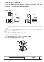
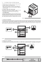
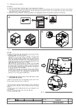
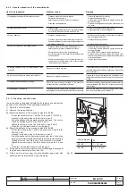
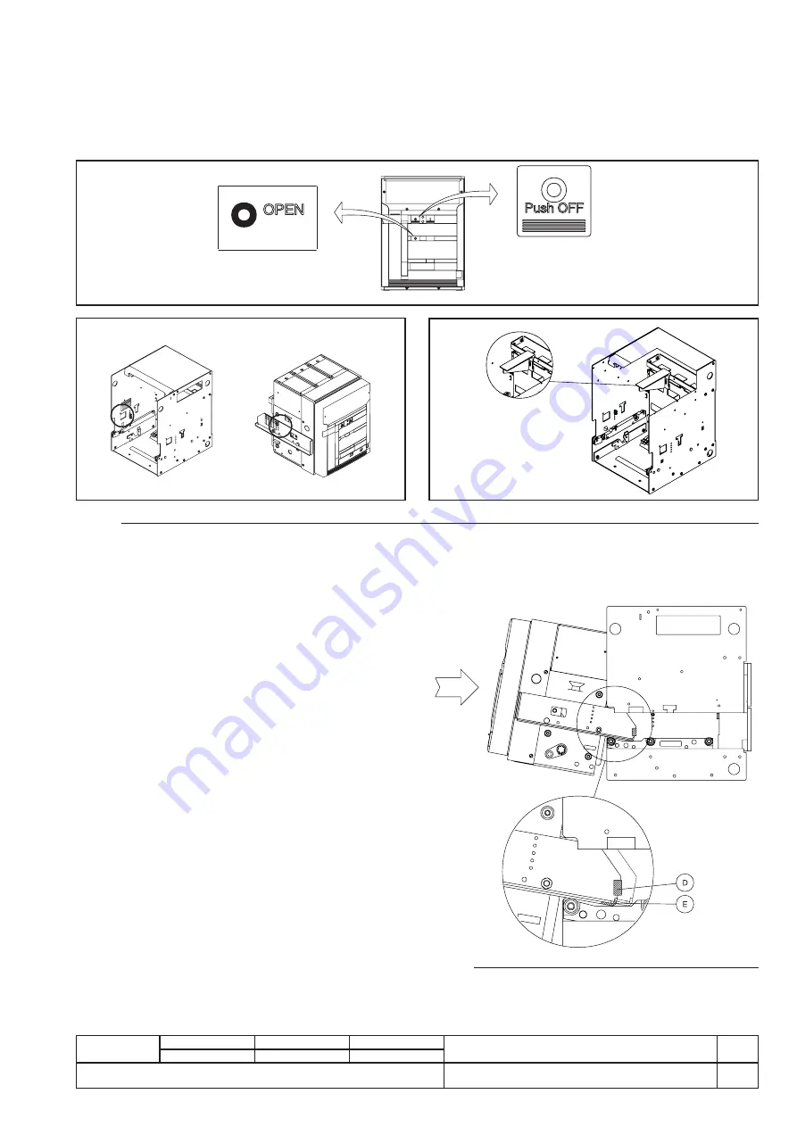
a ) Positioning the moving part in the fixed part in the
DISCONNECTED position
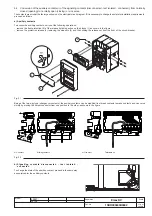
Lift the moving part as shown in the paragraph (3) and insert it in the
fixed part guide, tilting it as shown in figure 29.
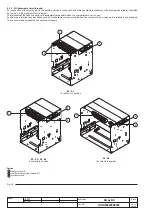
Fig. 29
The manual connection must allow the edge (E) of the circuit-breaker
guide to slide under the blocks (D) of the fixed part. Remove the lifting
devices.
The position reached is stable and allows for any inspections of the
circuit-breaker.
Push the moving part as far as the stop in the fixed part.
Close the compartment door.
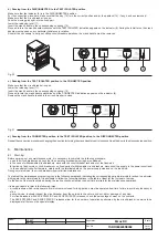
7.3 Racking-in/out operation
WARNING
A) Open the circuit-breaker before carrying out any racking-in/out operation.
B) The circuit-breaker (moving part) and fixed part are fitted with a lock which prevents the fixed part from being racked into the circuit-breakers
with a different rated current: the congruence of the anti-racking-in lock must be checked by the operator before carrying out the racking-
in operation to avoid any unnecessary stress.
C) Before the racking-in operation, remove any padlock on the segregation shutter of the isolation terminals on the fixed part.
Fig. 28
Press
N O T E S
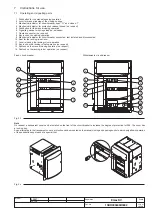
In relation to the fixed part, the circuit-breaker (moving part) can take
up different positions, identified as follows:
– DISCONNECTED: the moving part is inserted in the fixed part
WITHOUT any connection between the power terminals and
WITHOUT coupling the sliding contacts for the auxiliary circuits: in
this position all electrical operation of the circuit-breaker is prevented.
On the front the indicator (9, Fig. 23) indicates DISCONNECTED. The
switchgear compartment door can be closed.
– TEST ISOLATED: the moving part is inserted in the fixed part
WITHOUT any connection between the power terminals, but WITH
the sliding contacts coupled for the auxiliary circuits. In this position,
the circuit-breaker can be operated for the offline tests. The indicator
(9, Fig. 23) indicates TEST ISOLATED.
– CONNECTED: the moving part is fully inserted in the fixed part WITH
the connection of both the power terminals and the sliding contacts
for the auxiliary circuits. The circuit-breaker is operational. The
indicator (9, Fig. 23) indicates CONNECTED.

