L3447
Emax DC
101/108
Doc. No.
Model
1SDH000635R0002
Apparatus
Scale
Page No.
L3728
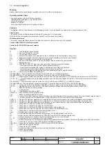
17. Circuit diagrams
Warning
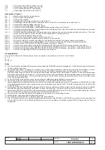
Before installing the circuit-breaker, carefully read note F on the circuit diagrams.
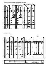
Operating status shown
The circuit diagram is for the following conditions:
- withdrawable circuit-breaker, open and racked-in
- circuits de-energised
- releases not tripped
- motor operating mechanism with springs unloaded.
Versions
The diagram shows a circuit-breaker in withdrawable version; it can be applied to a fixed version circuit-breaker as well.
Fixed version
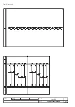
The control circuits are fitted between terminals XV (connector X is not supplied).
With this version, the applications indicated in figures 31 and 32 cannot be provided.
Withdrawable version
The control circuits are fitted between the poles of connector X (terminal box XV is not supplied).
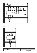
Version with PR122/DC electronic release
Version with PR123/DC electronic release
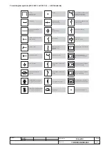
Caption
= Circuit diagram figure number
*
= See note indicated by the letter
A1
= Circuit-breaker accessories
A3
= Accessories applied to the fixed part of the circuit-breaker (for withdrawable version only)
A4
= Example switchgear and connections for control and signalling, outside the circuit-breaker
A13
= PR021/K signalling unit (outside the circuit-breaker)
D
= Electronic time-delay device of the undervoltage release, outside the circuit-breaker
F1
= Delayed-trip fuse
K51
= PR122/DC, PR123/DC electronic release with the following protection functions:
- L overload protection with inverse long time-delay trip-setting I1
- S short-circuit protection with inverse or definite short time-delay trip-setting l2
- I short-circuit protection with instantaneous time-delay trip-setting l3
- G earth fault protection with inverse short time-delay trip-setting l4 (only PR123/DC)
K51/1...8
= Contacts for the PR021/K signalling unit
K51/GZin(DBin)= Zone selectivity: for protection G (only with Vaux and PR123/DC release)
K51/GZout(DBout) = Zone selectivity: for protection G (only with Vaux and PR123/DC release)
K51/IN1
= Digital programmable input (available only with Vaux and release PR122/DC or PR123/DC with indicator module PR120/K)
K51/P1...P4 = Programmable electrical signalling (available only with Vaux and release PR122/DC or PR123/DC with indicator module
PR120/K)
K51/SZin(Dfin) = Zone selectivity: input for protection S (only with Vaux and PR122/DC or PR123/DC release)
K51/SZout(DFout) = Zone selectivity: output for protection S (only with Vaux and PR122/DC or PR123/DC release)
K51/YC
= Closing control from PR122/DC or PR123/DC electronic release with communication module PR120/D-M
K51/YO
= Opening control from PR122/DC or PR123/DC electronic release with communication module PR120/D-M
M
= Motor for loading the closing springs
Q
= Circuit-breaker
Q/1...27
= Circuit-breaker auxiliary contacts
S33M/1...3 = Limit contacts for spring-loading motor
S43
= Switch for setting remote/local control
S51
= Contact for electrical signalling of circuit-breaker open due to tripping of the overcurrent release. The circuit-breaker may be closed
only after pressing the reset pushbutton, or after energizing the coil for electrical reset (if available)
S75E/1.4 = Contacts for electrical signalling of circuit-breaker in disconnected position (only with withdrawable circuit-breakers)
S75I/1..5
= Contacts for electrical signalling of circuit-breaker in connected position (only with withdrawable circuit-breakers)
S75T/1..4 = Contacts for electrical signalling of circuit-breaker in test isolated position (only with withdrawable circuit-breakers)
CS
= Pushbutton or contact for closing the circuit-breaker
SO
= Pushbutton or contact for opening the circuit-breaker
SO1
= Pushbutton or contact for opening the circuit-breaker with delayed trip
SO2
= Pushbutton or contact for opening the circuit-breaker with instantaneous trip
SR
= Pushbutton or contact for electrical circuit-breaker reset
Vaux
= Auxiliary power supply voltage (see note F)
W1
= Serial interface with control system (external bus): EIA RS485 interface (see note E)
W2
= Serial interface with the accessories of PR122/DC and PR123/DC releases (internal bus)
X
= Delivery connector for auxiliary circuits of withdrawable version circuit-breaker
X1...X7
= Connectors for the accessories of the circuit-breaker
XF
= Delivery terminal box for the position contacts of the withdrawable circuit-breaker (located on the fixed part of the circuit-breaker)
XK1
= Connector for power circuits of PR122/DC and PR123/DC releases
XK2 - XK3 = Connectors for auxiliary circuits of PR122/DC and PR123/DC releases
XK4
= Connector to signal open/close
X O
= Connector for YO1 release
XV
= Delivery terminal box for the auxiliary circuits of the fixed circuit-breaker
YC
= Shunt closing release
Y O
= Shunt opening release

