background image

Standard Commissioning Process   85

Save all the files in project folder and attach to the report.

According to customer preferences, set the control panel language, parameter 96.01 
Language.

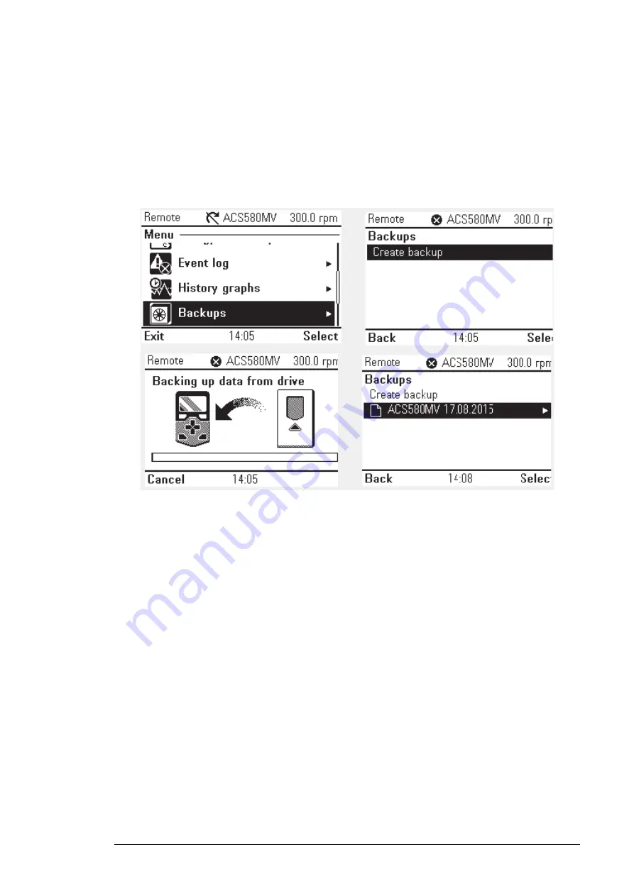
Save the parameter backup in ACS-AP-W/S panel. Option: Menu/Backups/Create 
backup

.

SD card data backup

Copy the Date from the SD memory card to PC.

Refer to 

Maintenance


in


ACS580MV Hardware Manual 

(2UBB004520), section 

Replacing the SD memory card

.

Spare parts software version

Before leaving the site, the customer spare parts are to be checked against the bill of 
material. If spare parts have not been ordered at all, the commissioning report is to be 
marked accordingly.

Spare parts of the customer containing software (BCON, ACS-AP-W/S, CVMI2, IO 
Controller, Control hub) are to be updated with the versions of the software and the 
parameters used in the converter.

Customer training

If not agreed by contract otherwise, the subjects listed below can be used as a guide when 
organizing on-site training of operational staff. The training can be based on the 

Operation


of


ACS580MV Hardware Manual 

(2UBB004520).

Содержание ACS580MV

Страница 1: ... ABB INDUSTRIAL DRIVES ACS580MV Commissioning Manual 200kW to 6300 kW 3 3kV to 11 kV ...

Страница 2: ...ual 2UBB005416 ACS580MV Manual Bypass unit Engineering Guideline 2UBB005683 ACS580MV Firmware Manual 3BHS811381 ACS580MV Troubleshooting manual 2UBB005092 ACS580MV Engineering Guideline 2UBB013672 ACS580MV_3 3 11KV_Line up_overview 2UBB005088 User s Manual Start up and maintenance PC tool Drivecomposer 3AUA0000094606 ACS580MV Preventive Maintenance Schedule 2UBB022658 ACS580MV Synchronized Bypass ...

Страница 3: ...0 kW to 6300 kW 3 3 kV to 11 kV 2UBB005441 Rev E EN EFFECTIVE 2021 07 15 2021 ABB Beijing Drive Systems Company Ltd Option Table of contents Preventive Maintenance Safety instructions Standard Commissioning Process Introduction to the manual ...

Страница 4: ......

Страница 5: ...ioning third party equipments 24 Main circuit breaker MCB 24 Power cables 24 Protection relays 27 Motor 28 Insulation Resistance Measurements 28 Preparations 28 External MCB Insulation Test 28 Converter Insulaiton Test 29 Motor Insulation Test 30 Power Cables Insulation Test 31 Preparing the converter for start up 32 Connecting the auxiliary supply 32 Check terminal X1 terminal before energizing a...

Страница 6: ...n and description of typical commissioning 95 4 Option MBU Commissioning 97 Insulation test 100 Commissioning for MBU 0001 option 100 Commissioning for MBU 0002 or MBU 0003 option 102 SBU Commissioning 105 Safety 105 Software requirements 105 Inspection of installation 105 Insulation test 106 Download software 106 SBU phase order check procedure 108 SBU Cold commissioning 111 SBU Hot commissioning...

Страница 7: ...ansformer insulation resistance 143 Motor insulation resistance 144 Optical fibers 144 Visual check 144 Attenuation measurement 144 Communication test 145 Bypass unit 146 Isolation switches for Manual Bypass 146 Contactor for Auto Bypass 146 ...

Страница 8: ...8 ...

Страница 9: ...tup guides step by step through the complete commissioning including reporting Equipment Frequency converter and related equipment EMC Electromagnetic compatibility All measures to suppress electromagnetic disturbances caused by different electrical equipment in the same electromagnetic environment and to strengthen the immunity of the equipment to such disturbances ESD Electrostatic discharge Gro...

Страница 10: ...distort voltage and current by its electrical systems PE Protective Earth PEBB Power Electronic Building Block semiconductor stack This is another term for power module Power module The power module is a compact assembly of electronic components including power semiconductors and circuit boards that serves as a standardized building block for the INU of the drive Safeline ABB synonym for uninterru...

Страница 11: ...which if not avoided will result in death or serious injury WARNING indicates a hazardous situation which if not avoided could result in death or serious injury CAUTION indicates a hazardous situation which if not avoided could result in minor or moderate injury DANGER Working on energized equipment can be a life hazard Mechanical forces electric shock and burn can cause severe injuries or death S...

Страница 12: ...sioning All openings of the motor must be closed and the shaft covers must be installed The area around the motor must be cordoned off to prevent accidents during the uncoupled motor tests All covers of power cable terminals or terminal boxes in converter motor transformers and MCB must be closed More details please refer to Safety instructions in ACS580MV Hardware Manual 2UBB004520 NOTICE Because...

Страница 13: ...he converter If agreed by contract the commissioning engineer who have gained the related certification can take on the commissioning of Motor MCB protection relays Manual Sync Bypass unit MSS MB Requirement for reports During the commissioning the Field Service Report and Commissioning Report should be prepared which are generated by the DriveStartup tool Service engineer shall upload the commiss...

Страница 14: ... get the license key Email address drivessupport abb com Queue in Salesforce GLO MO Global Drive support Exception different contacts for large countries China mv drives supportline cn abb com CN MOSE 4159 MV Drives Support India mv drives supportline in abb com IN MOSE Drives USA us drivessupport abb com US MO Drives Tech Support MV ...

Страница 15: ...ling to site Field service report template Programing software tools and DriveStartup software tool Copies of converter documentation commissioning manual wiring diagrams mechanical drawings and publications as per List of related manuals Information on the scope of delivery Information on latest SW and parameter updates contact MV Drives Supportline Information on possible converter upgrades Sett...

Страница 16: ...Code 3ABD00036680 Communication cable between PC and control panel 2 MC502 SD memory card Code 3ABD10058698 MC503 SD card adaptor Code 3AFE10094795 I O controller programing tool 3 USB XILINX HW USB II G Model DLC10 Code 3ABD00034510 Control Hub programing tool 4 USB 5V power cable Code 2UBA011603R0001 External power supply for power module 5 Multi Contact GRIP CI Code 3ABD00051018 4mm Safety Test...

Страница 17: ...al tools including nut driver screw driver and torque wrench etc 10 75 Nm for hexagon head screws M6 to M12 9 Insulation Tester Such as KYORITSU KEW3122A 10 General personal PPE safe helmet work clothes insulated shoes gloves earplug glasses Prevent Static suit etc No Name Pictures Descriptions ...

Страница 18: ...commended practice to photograph damaged equipment and send the photographs to ABB and the carrier Checking the pre conditions for commissioning In order to ensure uncomplicated and efficient commissioning it is important that converter and associated equipment are ready for commissioning The mechanical and electrical installation should be done as described in the ACS580MV Hardware Manual 2UBB004...

Страница 19: ...ross sections of control cables are suitable for the signal type and signal level The shield of analog cable need grounding properly Control cables are connected Customer interface is available in document MCB control cables are connected directly to the converter The wirings of remote control cabling are completed Cabling of options transformer motor protection tachometer etc are completed For MB...

Страница 20: ...l cables connecting with the converter is finished The user manual and technical specification is available Withstand voltage test of the MCB have been done according to manufacture specifications The official test report must be available Bolt size Bolt type Tightening torque Nm M3 Copper 0 8 M4 Steel Stainless steel 2 Copper 1 2 M5 Steel Stainless steel 3 Copper 2 M6 Steel Stainless steel 5 5 Co...

Страница 21: ...converter power module has been nonoperational for more than one year Without reforming capacitors may get damaged when the power module starts to operate Check the power module age Serial number of power module defines the week when it was manufactured For example 2UBA916040009 16 denotes manufacturing year 2016 04 manufacturing week 0009 running manufacturing number Regarding the instruction of ...

Страница 22: ...iently ventilated or cooled and dehumidification to ensure the converter can running at the appropriate temperature and humidity If operation with open doors filter of the room is available It is not allowed to operate with open door or windows of the electrical room if air is not filtered Air conditioning or ventilating duct of the drive room is ready for load run of the converter Regarding last ...

Страница 23: ...ng Converter The inspection includes the mechanical and electrical installation of the converter By visually checking the converter the commissioning engineer obtains an overview of the condition of the converter and can react in time if corrections have to be made Useful information about the requirements for the installation site is described in the ACS580MV Hardware Manual 2UBB004520 If the ins...

Страница 24: ...e test is performed with the MCB in test position Information on the required control interface to the converter and on the breaking time of the circuit breaker can be obtained from the ACS580MV Engineering Guideline 2UBB013672 and the converter wiring diagrams The following has to be checked It is forbidden to set common point for open status close status and ready status signals The MCB must ope...

Страница 25: ...sure the resistance of the output busbars by multimeter The typical values would be several ohms based on the motor data if the motor is connected Measure the resistance of the input busbars by multimeter The typical values would be several ohms if the TRU is connected and the MCB is not grounded then ground the MCB the values would be changed to nearly zero ohm ...

Страница 26: ...26 Standard Commissioning Process 1 Voltage dividers 2 Motor side terminals 3 Input terminals 4 Cable entry plate 5 Cabinet grounding busbar Terminal compartment original view from front ...

Страница 27: ...a current of a certain magnitude is allowed to flow until the relay opens the MCB There are three types of protection modes Instantaneous Short delay Time over current protection Transformer protection modes The recommend protection functions and setting values NOTICE The below mentioned settings are just informative for the commissioning engineer in which range the protection settings should be m...

Страница 28: ...measured insulation resistance value of the motor transformer or converter is too low the reason may be that insulators windings etc have moisture in them and it may be necessary to dry the windings It is advisable to compare the test results with the test reports from the supply factories The contractor or customer can make the insulation resistance measurements on the supply cables and motor in ...

Страница 29: ...uts and housings connect them to the high voltage circuit 8 Short circuit all isolation switches QS1 Q1 QS2 Q2 and QS3 Q3 of Manual bypass cabinet if MBU 0001 9 Short circuit all contactors KM1 Q1 KM2 Q2 and KM3 Q3 of Auto bypass cabinet if MBU 0002 or MBU 0003 10 Short X107 1 2 X10⁸ 1 2 Note terminal 2 was grounded already if SBU 0001 SBP 0001 11 Switch off PT power supply from customer side disc...

Страница 30: ...he insulation resistance measurement All resistance temperature detectors RTD must be grounded The insulation resistance of a new motor is normally very high A rule of a thumb can be that if the measured value is one decade or more lower than the value measured in the factory check the winding for excess moisture or dirt The test report contains the insulation resistance value measured in the fact...

Страница 31: ...esistance measuring when star point is not reachable 1 measuring value If the reading is too low dry the motor windings according to instructions in the motor documentation Power Cables Insulation Test Measure the insulation resistance of all power cables and write down the measured results Measurements have to be made between all phases all cables apart from each other and between all cables and ...

Страница 32: ...of the auxiliary power supply are located in the control cabinet Check terminal X1 terminal before energizing auxiliary supply In order to prevent device such as BCON AC500 etc from damaging by wrong wiring new design of X1 terminal with pluggable connectors Plug4P 5P was introduced The connectors are not allowed to be plugged into X1 until examination finished by service engineer as following pro...

Страница 33: ... close open status signal and measure voltage as below table the values should not be higher than 5V MCB status drawing Probe Probe AC DC X1 20 PE 5V 5V X1 22 PE 5V 5V X1 24 PE 5V 5V X1 26 PE 5V 5V X1 28 PE 5V 5V X1 30 PE 5V 5V PLC DI0 and DI1 F24V 5 and X24V1 4 ...

Страница 34: ...supply for the first time proceed as follows 1 Make sure that all auxiliary switches optional circuit breakers and protection switches inside the drive have been switched off 2 Before turning on the fuses and breakers measure the incoming auxiliary voltage and control voltage verifying that it is within 10 of the rated value Probe Probe AC DC X1 42 PE 5V 5V X1 44 PE 5V 5V X1 46 PE 5V 5V X1 48 PE 5...

Страница 35: ...eason just pull off the left side plug Cooling Fan wiring 4 If XDI interface on BCON is used please disconnect XDI terminals and inform customer send instruction accordingly to confirm there is no input voltage otherwise X10 X90 can be damaged 5 If XAI XAO interfaces on BCON are used please confirm input of XAI should be 0 2 10V or 0 4 20mA higher input can damage BCON BCON customer interface ...

Страница 36: ...our computer Check the software or firmware version from the routing test report or from the parameters group it is not demand to upgrade the boards which have the latest version installed Required hardware tools and accessories Personal computer with Windows 7 or Windows 10 32 bit or 64 bit and Office 2013 or above version installed USB transfer Mini USB cable 3M MC502 SD memory card MC503 SD car...

Страница 37: ... hash value of the software package a Open windows command prompt by clicking Start button and typing cmd to windows search b Go to directory containing your local copy of release zip file c Give following command to re calculate SHA 512 checksum certutil hashfile releasezipfile SHA512 Note This checksum is an example only Compare calculated checksum to checksum obtained from Medium Voltage Drives...

Страница 38: ...ioning Process Loading the BCON software Install the Drive_loader_2_3_setup tool or new to local PC Connect PC to the assistant control panel ACS AP W S through the USB to Mini USB cable Switch on the control power supply ...

Страница 39: ...Standard Commissioning Process 39 Start Drive loader 2 and select the file LP_FirmwareUpgrade lp from the loading package folder 01_BCON SW ...

Страница 40: ...40 Standard Commissioning Process Wait until the tool identifies the port and reads data from BCON Click Download button and wait until the download finished successfully ...

Страница 41: ...fo to check version of MHDFA and MHDAP Check if the date and time are correct otherwise set time Loading the ACS AP W S assistant panel firmware Remove the panel from the drive Connect PC to the assistant control panel ACS AP W or ACS AP S through the USB to mini USB cable ...

Страница 42: ...42 Standard Commissioning Process Start DLoaderWin32 exe from the loading package folder 05_ControlPanelFW Press the button Open select the dlp file in software package ...

Страница 43: ...Standard Commissioning Process 43 Press the button Load SW and wait till update is finished ...

Страница 44: ...ing the control hub firmware Install the XILINX lab tools 14 7 Copy the files as below to local disk unzip the first one Start the xsetup exe to install the software tool Note Do not connect Xilinx cable to PC during the whole installation ...

Страница 45: ...Standard Commissioning Process 45 In this step should select Lab Tools Standalone Installation ...

Страница 46: ... Install Cable Drivers Till to finish successfully Switch off the control power Remove the daughter boards DB2 and DB3 to get access the X5 connector on control hub Connect XILINX platform cable USB II to X5 connector on control hub Switch on the control power ...

Страница 47: ... Process 47 Run the PROG_MHDCH bat batch file to program the control hub folder 03_Controlhub FW Note If the error information like below it means that the location of the IMPACT program needs to be added to the system path ...

Страница 48: ... C xilinx 14 7 LabTools LabTools bin nt64 Open the System variables by the path Start Settings Control panel System and Security System Advanced system settings Environment variables Add to the value of Path in system variables the location of IMPACT exe as value This needs to be done only once ...

Страница 49: ...formation like below please create a folder named temp in drive C Waiting nearly 5 minutes programming successfully finished Press any key to exit Turn off the control power Remove the XILINX platform cable USB II Restore all daughter boards on control hub ...

Страница 50: ...ep Switch off the control power Connect XILINX platform cable USB II to X1301 connector on CVMI2 Switch on the control power Run PROG_LXES bat batch file to program the CVMI2 folder 06_CVMI2 FW Note If the error information like below it means that the location of the IMPACT program needs to be added to the system path ...

Страница 51: ... C xilinx 14 7 LabTools LabTools bin nt64 Open the System variables by the path Start Settings Control panel System and Security System Advanced system settings Environment variables Add to the value of Path in system variables the location of IMPACT exe as value This needs to be done only once ...

Страница 52: ...ve the XILINX platform cable USB II Loading the IO controller AC500eco software Save the following files and folders to the SD card MC502 root folder Files can be found in the loading package folder 04_IOController SW Note Only MC502 SD card can be used This is not the same SD card which is plugged into the BCU Switch off the control power Install SD card adapter MC503 into CPU PM55X Inset SD memo...

Страница 53: ... to power modules After MCB has been closed and medium voltage introduced to the converter power modules boot up BCON controller checks the SW version on each PM If the version on PMs is not the same as the SW defined version BCON will initiate SW downloaded to PMs Due to safety reason during SW download MCB will be open fault 607E PM software update in process is active The fault cannot be reset ...

Страница 54: ...lly to power modules Necessary tools 5 5 VDC power USB to POF cable and fiber cable Install the Tera term programing tool select the default components Check and confirm the drive has been discharged and door lock is released Open the INU door and then switch off the control power supply Connect the POF link to power module and USB to PC ...

Страница 55: ... from desktop such as COM12 Select serial port and set baud rate to 115200 from Properties Open the programing tool Tera Term Set the Serial Port to COM12 Same serial port as last step Open the workspace of Tera Term select the Setup Serial port Set the Baud rate to 115200 others settings keep the default values ...

Страница 56: ...ocess Connect the 5 5 VDC cable to power module X1 and PC Note terminal DC is the one which close to the fiber terminal The Tera Term will ask you whether to erase the flash Note If no action in 5 seconds we need reboot the board ...

Страница 57: ... Type e to erase the flash once erasing done step to Ready for application code transfer Open the File Send file select the PEBB1_CellController bin from the software package folder 02_PowerModule SW Note Confirm the Binary is enabled ...

Страница 58: ...ssioning Process Click the OPEN button to start programming Several seconds later the message is shown as below application is programed Repeat the steps to program all the power modules Disconnect the programing tools ...

Страница 59: ...rsion of DriveStartup that integrated into Drive composer pro One could get the new PC tools through downloading Drive composer pro The suggested Drive composer pro released is version 2 1 or newer To active the embedded version of DriveStartup one should register Drive composer pro by a special license Please contact MV Drives Supportline for solution Installation of Drive composer pro Download t...

Страница 60: ...60 Standard Commissioning Process Complete the installation press Finish ...

Страница 61: ...tration code from menu Help Enter license code Reboot the drive composer pro Open the DriveStartup tool from the Drive composer pro Start the registered Drive composer pro tool Launch the DriveStartup from the menu Tools Launch DriveStartup Confirm the Commissioning from Mode selection ...

Страница 62: ...62 Standard Commissioning Process DriveStartup launched OPC server does not need to set again Add the loading package from the menu View Package Manager ...

Страница 63: ...Standard Commissioning Process 63 Open the file from the below location folder 08_DriveStartup ACS580MV Add the template of Field service report also from the menu View Package Manager ...

Страница 64: ...ect Start the commissioning NOTICE In the display settings adjust view to be 100 DriveStartup informs to do this during installation Check the display setting on PC Control panel Appearance and personalization Display use the default selection Smaller 100 The recommend resolution of display is at least 1366x768 ...

Страница 65: ...CPR0004 CSC0001 CSV0003 DMT0001 SEO0000 CIT000 0 EXT0000 FAT0000 FAD0002 FWE0000 FAB0000 GDS0001 HWS0000 TRR0073 LOD0011 LCH0000 PCE0041 MCE0041 MCC0000 RMC0001 EAT0000 EWT0000 MOF0120 MST0000 MHP0000 TSM0000 OCH0000 OCA0000 PAK0000 CPF0002 TRV0000 SHT0000 SPP0000 SPF0050 SMV0066 CEP0012 PCM0100 WMT0001 The full type code can be copied from the project information in MoR by search the series numbe...

Страница 66: ...66 Standard Commissioning Process Site inspection step by step Take photos and prepare the ACS580MV Drive and Site Condition Check List Attached in the project folder once completed ...

Страница 67: ...ioning Process 67 Connected equipment inspection Fill in all necessary information from the equipment report Including protection relays MCB integrated transformer motor and power cables Note Check every item carefully ...

Страница 68: ...ation Check if the power cable connection on the secondar side of the integrated transformer is correct NOTICE The connection of power cable must be solid It is not allowed to have any washer between two cable lugs The tightening torque should follow ACS580MV Hardware Manual 2UBB004520 passed case failed case ...

Страница 69: ...vel once restarting the connection enter again the service level passcode if needed Check the SW or firmware version Note ACS AP W S version should be checked also folder 05_ControlPanel FW Set the license received from the MV Drives Supportline The Par 96 70 license state should be Time unlimited Note The position of BCON series number is shown hereunder NOTICE Below information should be provide...

Страница 70: ...plate for the following settings Whenever possible enter the values exactly as shown on the motor nameplate According to the requirement of customer and project side set the parameters which are specific for the project a Operation mode in parameter group 19 ...

Страница 71: ...on if need motor temperature cable temperature motor cooling fan in parameter group 35 Energy efficiency in parameter group 45 Monitoring and scaling in parameter group 46 Internal fieldbus settings in parameter group 54 Note Only save and set active default setting IO controller Local control disable in parameter group 81 Note Including the logic test refer to the DriveStartup MCB available MCB O...

Страница 72: ... in remote control mode According to the DriveStartup instruction conduct all the steps below Observe the MCB control and feedback signals in the graph a 11 01 DIO status bit0 MCB trip command 1 b 11 01 DIO status bit1 MCB status closed c 87 10 AC500 CPU DI status bit2 MCB OFF command front door d 87 10 AC500 CPU DI status bit3 MCB ON command front door e 87 10 AC500 CPU DI status bit4 MCB status ...

Страница 73: ...n front door MCB should be closed Press emergency off button on front door MCB should be opened and fault AFEB Emergency OFF button pressed is active Release emergency off button the fault should deactivated Press ON button on front door MCB should be closed Wait more than 3 seconds Fault E110 DC link charging timeout should activate MCB trips Zoom out the graph Verify that the MCB control and fee...

Страница 74: ...one can be active Transition from Converter to Bypass S2 can be closed only if S3 is open Transition from bypass to converter operation a S1 can be closed only after S2 has opened b S3 can be closed only after the drive is charged Bypass command given while the drive is not charged a While S3 is closed it has no effect S2 stays open b When S3 is open it is possible activate Bypass S2 closes Bypass...

Страница 75: ...ters the converter can be energized Close MCB and Load Power Module software After MCB has been closed and medium voltage introduced to the converter power modules PMs boot up BCON controller checks the SW version to each PM If all PMs don t have the same version or if the PM SW version is outdated BCON will initiate SW downloading to PMs Due to safety reasons during SW update MCB will be open fau...

Страница 76: ... and XFMR 6KV D560 D500 Fan box 687 O 46 0 600 1100 600 1100 600 1100 COU COU COU 600 1100 COU 600 1100 COU 600 1100 COU 600 1100 COU 600 1100 COU 600 1100 COU 600 1100 COU 600 1100 COU 600 1100 COU 600 1300 COU 600 1300 600 1300 600 1300 COU COU 600 1300 600 1300 COU COU COU Normal D500 D500 2XD500 2XD500 D500 D500 2XD500 2XD500 D500 D500 2XD500 2XD500 D500 D560 2XD500 2XD560 D500 D560 2XD500 2XD...

Страница 77: ...up during the operation try to disconnect the USB cable in online mode and connect the cable again after the DriveStartup announce the communication disturbing Press ON button on the front door drive will be charged and fans will run Observe the motor behavior in the graph below Start the motor to a low speed reference 10 of nominal value and check the rotation direction Increase the speed referen...

Страница 78: ...therwise skip this step Take the drive to Local control by DriveStartup select online mode Save and set following parameters a 21 19 Scalar start mode to Automatic b 21 03 Stop mode to Coast Set the speed reference to motor rated speed and start the motor When motor reaches the set point stop it and restart nearly 10s later Repeat the steps at different points as required confirm the motor can be ...

Страница 79: ...esn t perform negative speed search When motor is stopped with some load and motor is rotating in the negative direction Run the motor again with Automatic start mode Par 21 19 scalar start mode Automatic speed scan is performed and small positive speed is found even though motor is rotating in negative direction And then a No negative speed scan b Flux reference is ramped assuming that the motor ...

Страница 80: ...er 19 11 Ext1 Ext2 selection The source of reference is selectable for each operating mode separately For speed reference setting go to parameter group 23 if Rpm is used or parameter group 28 if Hz is used For fieldbus setting go to parameter group 50 51 52 53 Release the local control button on DriveStartup only record the graph in this step Check the parameters are correctly set regarding extern...

Страница 81: ...t in death or serious injury After the motor has been coupled and run with the driven equipment all interlocks from an overriding control system must be in operation These interlocks should stop the drive if a critical condition occurs in the process If the trip levels acceleration or deceleration times are set wrong it may cause mechanical damages on the application or interrupt the process ...

Страница 82: ...low parameter setting a Parameter 21 Start Stop mode b Parameter 23 Speed reference chain c Parameter 28 Frequency reference chain Observe and save the measurement attach plot to report Run the motor for a while from customer control while you fill in the paperwork Vector Control Before doing vector control related test configure the drive as normal with scalar control mode according to normal ser...

Страница 83: ...Standard Commissioning Process 83 ...

Страница 84: ...rated motor speed is reached The MCB opens and closes after specified time The drive should not trip due to overcurrent motor or transformer The DC voltage should be below limit at all time After MCB is closed motor speed should return to rated value without overshoot Finalizing the commissioning Parameters backup Export parameters to a prn file using DriveStartup option Parameters Export Use Driv...

Страница 85: ...s software version Before leaving the site the customer spare parts are to be checked against the bill of material If spare parts have not been ordered at all the commissioning report is to be marked accordingly Spare parts of the customer containing software BCON ACS AP W S CVMI2 IO Controller Control hub are to be updated with the versions of the software and the parameters used in the converter...

Страница 86: ... graph c Create the support package Copy the SD card date from the drive Standard troubleshooting process and where to get help Customer approval After the test runs have been performed and the Commissioning Report has been filled in completely the representative of the customer is asked to confirm the end of the commissioning with his her signature on the report Date and signature on the report w...

Страница 87: ...e latest Field Service Report template version 2 0 or newer from the MV Drives Portal Software Station and only use the latest version for all future reports When you create a DriveStartup project please include the field report with the drive commissioning packages Open the DriveStartup add the Field Service Report template through the menu View Package Manager ...

Страница 88: ... fill out the full information After loading the data from MoR database suggest to review the drive information and service history through the installed base information NOTICE In the display settings adjust view to be 100 DriveStartup informs to do this during installation Check the display setting on PC Control panel Appearance and personalization Display use the default selection Smaller 100 ...

Страница 89: ...egistered to a site customer in ServIS the Registration step appears Please locate the correct site with the link in ServIS and copy the Site ID to the ServIS Site ID box After you upload the report MoR moves drive to the site in ServIS The BoM which includes the serial numbers of the most important components can be synchronized by the field service report ...

Страница 90: ...is currently installed in the drive Fill in the responding information in the blanks below If the serial number and position number of the fault material is just the same with the ones in original BOM fill in right in part status if not fill in wrong After saving the date the material which has been revised will changed as picture below Make sure the serial number of the Material you return to fac...

Страница 91: ...the quality of our data All the drive data that is collected in Drive Data and Software step should be added to the table including the firmware and software version of AC500eco ACS AP S W BCON CVMI2 and Control hub The parameter backup parameter export and SD card data of BCON should be added to the table also Complete and upload all the information and data described in the steps ...

Страница 92: ...correct drive status in step Service summary Which would impact the drives life time management in MoR database Return to the step Reports and attachment Create the service report and field service report by going to menu Reports and select report type ...

Страница 93: ...n report 2UBB021641_ACS580MV Drive and Site Condition Check List together with the commissioning report service report and field service report add to the attachment Update all the drive data and reports to MoR by pressing Upload ALL to Installed base MoR button ...

Страница 94: ...ter assistance of the customer send the following to the MV Drives Supportline Copy of the commissioning report MoR database Copy of the field service report MoR database 2UBB021641_ACS580MV Drive and Site Condition Check List MoR database Copy of the parameter backup files MoR database a prn txt file customer access level b dcparamsbak file service access level SD card data MoR database Copy of m...

Страница 95: ...ing the environment of electrical room Safety cooling capacity etc Checking mechanical installation of the converter supply transformer motor and MCB Checking power cables installation routing length dimensioning etc Checking the grounding cables installation earth and equipotential cables Performing insulation tests on all drive system components if drive stock more than six months 2 Switching on...

Страница 96: ...96 Standard Commissioning Process ...

Страница 97: ... or drive maintenance then the motor can be switched to bypass DOL mode As standard option there are 3 types shown as below MBU 0001 Line up manual version with isolation switches MBU 0002 Line up electrical operated manual bypass with vacuum contactors MBU 0003 Line up premium electrical operated manual bypass ...

Страница 98: ...double checking schematics IO interface and the customer wiring before commissioning due to customer interface changed If drive still using old design please make sure pin3 or pin4 cannot have common grounding with pin1 pin2 pin5 and pin6 DANGER Three isolation switches are forbidden to be operated when MCB is closed Illegal operation will result in death or serious injury The position of the kniv...

Страница 99: ...Option 99 Customer interface or MBU New Customer interface or ABU Old Customer interface or ABU New New relay for Manual bypass unit upgrade ...

Страница 100: ...as been racked out and grounded Ground the input busbar in TRU cabinet by grounding harness for safety Connect the control cables among the MCB MBU and COU cabinet Disable the local close push button on MCB cabinet Connect the auxiliary control power supply to the cabinet Check of the isolation switches position Follow the operation sequence operate the switches of QS1 Q1 QS2 Q2 and QS3 Q3 ...

Страница 101: ...s For lamp test the cabinet shall be fed Auxiliary supply and close Q7101 and Q7151 The lamps status can be checked as below table Item QS1 Q1 open QS2 Q2 open QS3 Q3 close Bypass mode QS1 Q1 open QS2 Q2 open QS3 Q3 open OFF mode QS1 Q1 close QS2 Q2 open QS3 Q3 open QS1 Q1 close QS2 Q2 close QS3 Q3 open VSD mode Result Aux Supply lamp On On On On QS1 Q1 _close lamp Off Off On On QS1 Q1 _open lamp ...

Страница 102: ...the drive Confirm the MCB is open select the Bypass mode monitor and run the motor by the overriding system Commissioning for MBU 0002 or MBU 0003 option Confirm the MCB has been racked out and grounded Ground the input busbar in TRU cabinet by grounding harness for safety Connect the control cables among the MCB MBU and COU cabinet Disable the local close push button on MCB cabinet Connect the au...

Страница 103: ...all be changed after operating Contactors operation Local mode stop mode remote mode Remote operation Local operation Remote operation Local operation KM1 Q1 _close X X X X KM1 Q1 _open X X X X KM2 Q2 _close X X X X KM2 Q2 _open X X X X KM3 Q3 _close X X X X KM3 Q3 _open X X X X Contactors status S7804 Local status Contactors operate Local S7804 Remote status Contactors operate Remote KM1 Q1 open ...

Страница 104: ...e Confirm the MCB is at the test position switch the S7804 to Local mode set to the Bypass mode Close the MCB by overriding system Confirm the MCB is at the test position switch the S7804 to Remote mode set to the Bypass mode Close the MCB by overriding system Rack in the MCB to the operation position From this time on the medium voltage can be connect to the MBU and drive Confirm the MCB is open ...

Страница 105: ...orking on the equipment Safety instructions must be strictly followed Non compliance can jeopardize the safety of personnel the equipment and the environment Refer to Safety instructions Software requirements The Latest software is recommended Inspection of installation Complete installation checklist before commissioning can take place See ACS580MV Hardware Manual 2UBB004520 for other information...

Страница 106: ...nd verify that it is within 10 of its nominal value Auxiliary power ground control and serial communication cables made properly Options cabinet heater CP610 etc supply cabling properly made Power cables for SBU functions are made and installed properly including converter output to MSS MSS to motor MB to motor grid to MB Interface cables for SBU function control device to ACS580MV are properly ma...

Страница 107: ...g your finger for a few seconds on the screen and then select Update The panel system will check for the presence of the program package in the USB disk root folder and ask for update Select Auto select best match and click next The update will start automatically On the CP610 press an empty area of the screen for a few seconds to display the context menu Select Show system setting then set the IP...

Страница 108: ...ineering practice how it s conducted which is common to all other products with SBU function instead of something specially for ACS580MV Meanwhile SBU commissioning needs to count on expertise of FSE to judge on site which method is safe applicable and easy to carry out most of the time a common method will not work out one network two network ...

Страница 109: ...ose MSS1 in test position 5 Check the underside phase order of MCB and MB1 with multimeter at measuring points one by one Make sure the phase order of this circuit is correct 6 Check other main circuits phase order as the same procedure one by one if SBM 0002 Phase order check for PTs 1 Check the primary cable connection of PTs and make sure the phase order is correct 2 Check the wirings connectio...

Страница 110: ...I6 is low 6 Close Q2 and check if the indication lamp of SYNC is on and BCON DI6 is high ON means phase sequence is correct for both measurement loop from X107 X108 to Rsyc 01 board 7 If SYNC is not ON check phase sequence of the cable connection between X107 or X118 X108 or X118 and Rsyc 01 board correct the cable connection and redo the test Other failure modes include fuse broken X107 X108 X117...

Страница 111: ... open and close are used for MSS control this parameter needs to set 16 21 DIO3 output source P 85 2 14 MSS open command signal is from SBU function SW bit 14 If two signals open and close are used for MSS control this parameter needs to set 16 24 DIO4 function Output Select the DIO4 as the output If two signals open and close are used for MB control this parameter needs to set 16 26 DIO4 output s...

Страница 112: ...PT potential transformer For example if the ratio of PT is 11000V 110V set this value to 100 If the PT is provided by ABB the type is RZL10 11000V 110V 85 06 Ratio of converter voltage transducer 100 Refer to 85 05 85 11 SBU function enable enable Enable SBU function 85 12 Motor control mode Single motor example If no MAU PLC is selected MSS MB control signals are from FIO 01 set it to Single moto...

Страница 113: ... 85 20 MB open by direct online Disabled example If it s enabled 1 0 of MB DOL command BCU DI4 or 85 01 SBU control and monitoring CW bit 2 will open MB For Multi motor disabled is necessary 97 40 Output choke inductance 1 48mH example Define the inductance of the output choke 97 46 SBU current control gain 0 25 example Gain for current close loop control The value needs to be confirmed during com...

Страница 114: ...nd PC with ethernet cable Set Marshalling PLC optional and Panel optional as below table set the PC IP address in the same segment e g 192 168 0 13 and with same Subnet mask Drive parameter Setting Description 16 19 DIO3 function Output Select DIO3 as output 16 21 DIO3 output source P 85 2 14 Inductor bypass contactor close command signal is from SBU function SW bit 14 16 24 DIO4 function Output S...

Страница 115: ... example Define how many feedback signals MB has Par 4 MSS feedback signal TWO example Define how many feedback signals MSS has Par 5 MB command signal Pulse example Define control signals type of MB Par 6 MSS command signal Pulse example Define control signals type of MSS Par 7 MB pulse time 3s example Define pulse time of MB control signal Par 8 MSS pulse time 3s example Define pulse time of MSS...

Страница 116: ...IO configuration fault Par 50 Motor 1 user set UserSet1 example This parameter selects the user set for this motor Two types of motors are supported and user set is used to select the corresponding motor data The command is from marshalling PLC to BCU DI5 to select user set Every time after Motor group 1 8 selection is set marshalling PLC will select corresponding use set Detailed steps 1 Using mo...

Страница 117: ...ng pictures System Configuration Note It is important to set Par 2 number of motors at first More Marshalling PLC parameters please refer to ACS580MV Marshalling Unit firmware manual 2UBB005340 Select Motor1 4 and Motor5 8 to set motors parameters according to Par 2 the quantity of the motors ...

Страница 118: ...These command signals are available when Parameter 1 Control source selects IOs Position Type Number Name EMB CPU PM556 TP ETH DI2 Reset EMB CPU PM556 TP ETH DO1 Fault EMB P1 DI562 DI1 Motor 1 selection EMB P1 DI562 DI2 Motor 2 selection EMB P1 DI562 DI3 Motor 3 selection EMB P1 DI562 DI4 Motor 4 selection EMB P1 DI562 DI5 Motor 5 selection EMB P1 DI562 DI6 Motor 6 selection EMB P1 DI562 DI7 Motor...

Страница 119: ...r setting Access data setting for communication For status word control word and fault word please refer to ACS580MV Marshalling Unit firmware 2UBB005340 3 Panel control source Panel control is an option for customers The control interface is applied only when EMB P1 DI562 DI14 Motor 6 direct online EMB P1 DI562 DI15 Motor 7 direct online EMB P1 DI562 DI16 Motor 8 direct online Access type Name Ad...

Страница 120: ...ption Parameter 1 Control source selects Panel You can see all the panel interface after you log in the system as below Main interface NOTICE Only after user logs in the control command can be sent to system ...

Страница 121: ...Option 121 IO signals ...

Страница 122: ...122 Option Panel control interface System fault ...

Страница 123: ... For multi motor mode a Set and save 85 12 to multiple motors mode b Make sure 85 14 is set to Steady signal c Make sure 85 15 is set to Steady signal d Connect your PC with marshalling PLC Motor selection set will close corresponding MSS and motor selection unset will open corresponding MSS MB can be controlled by DOL signal after enabling corresponding MB open DOL and MB close DOL functions DANG...

Страница 124: ...85 12 is single motor mode Test steps 1 Let drive in remote mode and start monitoring trend 2 Give MCB close command and start command Set a reference and wait for drive reaches the setpoint 3 Force DI2 drive will go to sync to main mode After sync is finished MSS will open and MB will close 4 Open MB For multi motor mode DANGER From this step MCB and all of MB MSS is in normal position and contro...

Страница 125: ...c to main mode After sync is finished MSS will open and MB will close 5 Open MB 6 Test sync bypass of other motors 7 Test other functions for example different motor types different girds Panel Synchronization process The reading of a complete synchronization should look as follow Colour Name Blue RSYC 01 board BUFOUT signal for frequency speed adjusting Red Motor frequency speed Green RSYC 01 SYN...

Страница 126: ...ization when the amplitude frequency and phase angle of converter output voltage and grid voltage are within the limit the converter output current is measured and the converter is switched to current control After MB closed feedback is received current amplitude reference will ramp down to zero and then converter stops modulation After that MSS will open and synchronization to grid is finished SB...

Страница 127: ...losed while its performance can be changed via tuning the SBU current gain parameter value As a reference for tuning of the gain the typical value of inrush current is around 1 2 times nominal value of drive output current Note that the gain parameter 97 46 can be tuned in both directions to get the optimal setting Inrush current p u max motor current converter nominal current sqrt 2 ...

Страница 128: ...128 Option The graph should be similar to the example below Notice Please remember to attach the datalogger recording to the data uploaded to MoR Observe and save the measurement attach plot to report ...

Страница 129: ...shafts of Master and the Follower drives are coupled flexibly so that a slight speed difference is possible Drooping rate can be set to adjust speed dynamically for load balancing of master and followers Follower is torque controlled when the motor shafts of Master and the Follower drives are coupled solidly to each other There are two kinds of Fault maybe occur during using M F function One is 75...

Страница 130: ...re following items have been checked before M F test 1 All drives have been tested completely as vector control mode 2 Check M F link and make sure the fiber optical connected properly 3 Master Follower options ticked in Converter configuration Vector control is the recommended control method for Master Follower applications ...

Страница 131: ...Option 131 General parameter setting Parameters setting in this section is just for your reference The specific parameters should be set according to the user s control requirements ...

Страница 132: ...set P62 4 10 61 1 M F data 1 selection CW 16bit Master selects the data which transmit to the Followers The data value shown as P61 25 27 61 2 M F data 2 selection Other P23 2 61 3 M F data 3 selection Torque reference used 62 4 Follower node 2 data 1 sel Follower SW Optional Master selects the data which receive from the Followers The data value shown as P62 28 36 62 5 Follower node 2 data 2 sel ...

Страница 133: ...and they are effective when this follower is selected by Master s P60 14 61 2 M F data 2 selection User dependent 61 3 M F data 3 selection User dependent ACS580MV Follower Parameter Settings Speed Follower Parameter Name Setting Description 19 11 Ext1 Ext2 selection Ext2 19 14 Ext2 control mode Speed 20 6 Ext2 commands M F link 20 7 Ext2 start trigger type level 22 12 Speed ref2 source M F refere...

Страница 134: ...n example a Set BCU1 as master BCU2 as follower running at speed mode it follows master s speed BCU3 as follower running at torque mode it follows master s torque b SetBCU2as master BCU1 as follower run at speed mode it follows master s speed BCU3 as follower run at torque mode it follows master s torque 61 1 M F data 1 selection SW 16bit Optional Follower select the data which transmit to the mas...

Страница 135: ...1 M F data 1 selection Follower CW 61 02 M F data 2 selection Used speed reference 61 03 M F data 3 selection Torque reference used 62 01 M F data 1 selection CW 16bit 62 02 M F data 2 selection Ref1 16bit 62 03 M F data 3 selection Ref2 16bit 20 01 Ext1 command In1 start In2 Dir 20 06 Ext2 command M F link 22 11 Speed ref1 source P47 1 22 12 Speed ref2 source M F reference 1 22 14 Speed ref1 2 se...

Страница 136: ...r True 19 11 Ext1 Ext2 selection EXT2 19 14 Ext2 control mode Speed 60 15 Force master True 19 11 Ext1 Ext2 selection EXT1 19 12 Ext1 control mode Speed 60 15 Force follower True 19 11 Ext1 Ext2 selection EXT2 19 14 Ext2 control mode Torque Step5 BCU1 is follower 3 13 M F or D2D ref 1 200 3 14 M F or D2D ref 2 15 1 1 Motor speed used 200 BCU2 is master Start DI1 1 give load 15 1 1 Motor speed used...

Страница 137: ...ivate XETH port for NETA 21 connection NETA 21 Setup 1 Download latest firmware and package to NETA 21 and login by using local Ethernet cable 2 Set BCU SD upload to Latest month Find it in Settings Device Interface Ethernet Settings ...

Страница 138: ...138 Option 3 Setup ETH1 port 4 Setup ETH2 port NOTE Settings in the picture is just an example it works only for China domestic installation with 4G router 5 Reboot NETA 21 ...

Страница 139: ...Option 139 Finalizing the connection When NETA 21 is connected to network 4 green ticks will appear on the home page of NETA 21 Send detailed record list to Follow The Sun Supportline ...

Страница 140: ...140 Option ...

Страница 141: ... of the drive The drive should be checked at least every two years by qualified personnel whose recommendations should be followed Depending on the actual condition of the drive the maintenance work can be carried out before or after the recommended interval WARNING Obey the instruction in Safety instructions of ACS580MV Hardware Manual 2UBB004520 If you ignore them injury or death or damage to th...

Страница 142: ...start date for the preventive replacement schedule is the commissioning completion date or 2 years after delivery whichever comes first Inspection action Interval years Inspection Type Filter mats replacement 0 5 R Power Module R1 R9 1 I or R Transformer 1 I or R Optical fibers 1 P Cable connections bolted connections 1 I Dustiness Corrosion and overheating 1 I Software hardware upgrades 2 I or P ...

Страница 143: ...y control serial communication and ground cables Ground the transformer cabinet 4 Short circuit and ground the primary side of the transformer 5 Short circuit and ground all auxiliary windings heating cables and PT100 Measurement setup for transformer 6 Short circuit and ground all secondary three phase winding systems 7 Prepare the 5kV insulation resistance tester 8 Connect plus terminal to secon...

Страница 144: ...Visual check Pay special attention to the following 1 Cracks in the core or the coating 2 Minimum bend radius 25 mm 3 Condition of male and female connectors 4 Installation across sharp edges 5 Tightness of cable ties Attenuation measurement 1 Prepare the tools for attenuation measurement Tempo 253B light source 1 Tempo 557B power meter 2 10ZP adapter ...

Страница 145: ...lf optical power 2 Observe the following parameters within 30 minutes 70 12 32 52 Hub RX comm err count A1 A2 A3 71 12 32 52 Hub RX comm err count B1 B2 B3 72 12 32 52 Hub RX comm err count C1 C2 C3 70 5 25 45 PM RX comm err count A1 A2 A3 71 5 25 45 PM RX comm err count B1 B2 B3 72 5 25 45 PM RX comm err count C1 C2 C3 3 The observed RX comm err counters can have an initial value which may differ...

Страница 146: ...face of isolation switches apply more if necessary 3 No loose connection 4 Check status lamps on front door by operating isolation switches 5 Check interlock of isolation switches as the table below Note X means the operation cannot be executed means the operation can be executed Any of switches cannot be operated when the selector is in Operation or OFF position Contactor for Auto Bypass Pay spec...

Страница 147: ...mounted 2 Connection points no overheating corrosion or rustiness 3 Mechanical latch no damage deformation or rustiness 4 Auxiliary contacts no corrosion moving contacts acts easily after pressing connection rod 5 Check interlock of isolator knife switches as below table ...

Страница 148: ...148 Preventive Maintenance ...

Страница 149: ...ce contacts can be found by navigating to abb com searchchannels Product training For information on ABB product training navigate to new abb com service training Providing feedback on ABB Drives manuals Your comments on our manuals are welcome Navigate to new abb com drives manuals feedback form Document library on the Internet You can find manuals and other product documents in PDF format on the...

Страница 150: ...abb com drives 2021 ABB Beijing Drive Systems Company Ltd 2UBB005441 Rev E EN 2021 07 15 2021 ABB Beijing Drive Systems Company Ltd ...

Отзывы: