


91
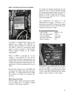
Phase and Brownout Protection Module
The DPM is a Digital Phase Monitor that
monitors line voltages from 200VAC to
240VAC 1
ɸ
and 200VAC to 600VAC 3
ɸ
.
The DPM is 50/60 Hz self-sensing. DPM
must be wired according to unit specific
wiring diagram include in the control
compartment
When the DPM is connected to the line
voltage, it will monitor the line and if
everything is within the setup parameters, the
output contacts will be activated. If the line
voltages fall outside the setup parameters, the
output relay will be de-energized after the trip
delay.
Once the line voltages recover, the DPM will
re-energize the output relay after the restart
time delay. All settings and the last 4 faults
are retained, even if there is a complete loss
of power.
DPM Setup Procedure
With the supply voltage active to the module,
you can setup all of the DPM’s settings
without the line voltage connected.
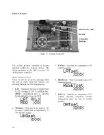
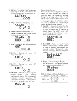
To change the setpoint parameters use the
right arrow key to advance forward through
the setpoint parameters and the left arrow to
backup if needed. When each parameter is
displayed use the up/down keys to change
and set the parameter.
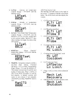
After adjustments are made or if no
adjustments are made it will take 2 to 4
minutes before the DPM energizes the output
relay unless there is an out of tolerance issue
with the incoming line voltage.
Recommended Default Set-up
Line Voltage
460VAC, 3Ø
Over & Undervoltage ±10%
Trip Time Delay
5 Seconds
Re-Start Time Delay
2 Minutes
Phase Imbalance
5%
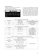
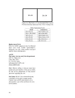
Phase and brownout module may be this type
on some products (as seen in the above
picture). No setup is needed with this module
version, other than checking that the voltage
jumper voltage matches the unit voltage
Содержание RQ NextGen Series
Страница 2: ......
Страница 26: ...26 Figure 3 RQ Cabinet Standard and Power Exhaust Gasket Locations...
Страница 40: ...40 Figure 23 Post Corner Hole Piping Figure 24 Post Back Hole Piping...
Страница 86: ...86 Figure 35 Example 2 6 ton through the Base Gas Piping Note RQ units will only contain one Heat Exchanger...
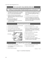
Страница 88: ...88 Gas Heater Operating Instructions Figure 36 Gas Heater Instructions...
Страница 95: ...95...
Страница 96: ...96...
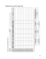
Страница 105: ...105 Maintenance Log E Coated Coil...
Страница 107: ...107...


