50
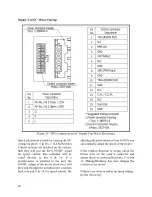
Freeze Stat Startup
Freeze Stat is an
adjustable temperature
sensor (-23.3
°
C to 21.1
°C [
-10 to 70°F])
mounted on the tubing of the first cooling
circuit and wired to de energize all cooling
circuits if tubing temperature falls below
setpoint. Option is used to prevent freezing of
evaporator coil.
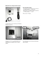
Recommended Setting
:
0
°
C to 1.7
°
C (32
°
F
to 35º F
Condenser Fan EC Motor Startup
The fan cycling option uses a fan cycle switch
to switch between one of the discrete speed
inputs (see Table 17) on the motor thus
cycling between two preset speeds based
upon discharge pressure of the unit. By
connecting 24VAC to a single or
combination of the yellow, white, or orange
wires, the motor will run at the discrete
speeds in Table 17.
AAON Condenser Head Pressure Module is
used for variable speed control of the motor
to maintain a head pressure. The motor must
be factory wired to the PWM outputs of the
AAON Condenser Head Pressure Module.
See AAON literature for further information
(https://www.aaon.com/Controls).
Note
High voltage wires out of the motor:
Black & Brown – 1 Phase Line Voltage
Green - Ground
Low control voltage wires out of the motor:
Blue – Common
Yellow – Variable Speed Control
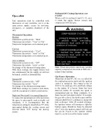
Table 17 - EC Condenser Fan Cycling Options
Color
Terminal
Customer
Connection
Option 1
Option 2
Option 3
Option 4
Option 5
Black
0.50 BWS
L1
208-230 VAC
208-230 VAC
208-230 VAC
208-230 VAC
208-230 VAC
Brown
0.50 BWS
L2
208-230 VAC
208-230 VAC
208-230 VAC
208-230 VAC
208-230 VAC
Green
#10
EYELET
Ground
GND
GND
GND
GND
GND
Blue
0.50 BWS
Common
Common
24 VAC
24 VAC
24 VAC
24 VAC
Yellow
0.50 BWS
Signal
PWM
24 VAC
24 VAC
White
0.50 BWS
Signal
24 VAC
24 VAC
Orange
0.50 BWS
Signal
24 VAC
24 VAC
RPM
300-1100
300
500
850
1100
Rotation
CCW
CCW
CCW
CCW
CCW
ECM Toolbox ID
Variable
Speed 4
Speed 3
Speed 2
Speed 1
20% PWM RPM
300
100% PWM RPM
1100
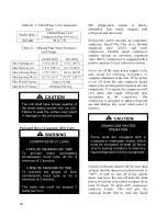
DO NOT OVERCHARGE!
Refrigerant overcharging leads to
excess refrigerant in the condenser
coils resulting in elevated compressor
discharge pressure.
CAUTION
Содержание RQ NextGen Series
Страница 2: ......
Страница 26: ...26 Figure 3 RQ Cabinet Standard and Power Exhaust Gasket Locations...
Страница 40: ...40 Figure 23 Post Corner Hole Piping Figure 24 Post Back Hole Piping...
Страница 86: ...86 Figure 35 Example 2 6 ton through the Base Gas Piping Note RQ units will only contain one Heat Exchanger...
Страница 88: ...88 Gas Heater Operating Instructions Figure 36 Gas Heater Instructions...
Страница 95: ...95...
Страница 96: ...96...
Страница 105: ...105 Maintenance Log E Coated Coil...
Страница 107: ...107...

