


61
accumulation out of the compressor before it
is started.
Always control the unit from the thermostat,
or control panel, never at the main power
supply, except for servicing, emergency or
complete shutdown of the unit.
During the cooling season, if the air flow is
reduced due to dirty air filters or any other
reason, the cooling coil can get too cold
which will cause excessive liquid to return to
the compressor. As the liquid concentration
builds up, oil is washed out of the
compressor, leaving it starved for lubrication.
The compressor life will be seriously shorted
by reduced lubrication and the pumping of
excessive amounts of liquid oil and
refrigerant.
Note:
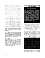
Low Ambient Operation
Air-cooled DX units without a low ambient
option, such as condenser fan cycling or the
-17.8°C (0°F) low ambient option, will not
operate in the cooling mode of operation
properly when the outdoor temperature is
below 12.8°C (55°F). Low ambient and/or
economizer options are recommended if
cooling operation below 12.8°C (55°F) is
expected.
Note:
Multiple Units with Multiple
Thermostats
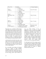
When several heating and cooling units are
used to condition a space, all unit thermostat
switches must be set in either heating mode,
cooling mode or off. Do not leave part of the
units switched to the opposite mode. Switch
off cooling only units at the thermostat during
the heating season.
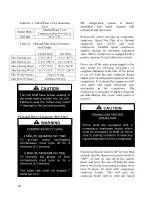
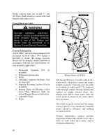
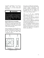
Variable Capacity Compressor
Controller
Units with variable capacity scroll
compressors may include the following
compressor controller. The following is an
explanation of the terminals and
troubleshooting alert flash codes of the
controller. For more information on the
compressor controller, see Emerson Climate
Bulletin AE8-1328.
Note:
When using field controls any variable
capacity compressors must run at 100% for 1
minute when starting.
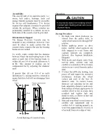
Figure 29 - Variable Capacity Compressor
Controller
Low Voltage Terminals
24COM
Module Common
24VAC
Module Power
C1 & C2
Demand Input
P1
Pressure Common
P2
Pressure Input
P3
Pressure Power 5VDC
P4
Pressure Shield
P5 & P6
Pressure Output
To avoid damaging the Compressor
Controller do not connect wires to
terminals C3, C4, T3, T4, T5, or T6.
WARNING
Содержание RQ NextGen Series
Страница 2: ......
Страница 26: ...26 Figure 3 RQ Cabinet Standard and Power Exhaust Gasket Locations...
Страница 40: ...40 Figure 23 Post Corner Hole Piping Figure 24 Post Back Hole Piping...
Страница 86: ...86 Figure 35 Example 2 6 ton through the Base Gas Piping Note RQ units will only contain one Heat Exchanger...
Страница 88: ...88 Gas Heater Operating Instructions Figure 36 Gas Heater Instructions...
Страница 95: ...95...
Страница 96: ...96...
Страница 105: ...105 Maintenance Log E Coated Coil...
Страница 107: ...107...


