Chapter 1: Introduction
10
ZP2 Series Installation Manual
There are two fire routing output groups, the first is in activated status and the
second is in acknowledged status. The fire routing indication displays the
acknowledged status but not the activation status (the acknowledgement status
takes priority).
For more information on output groups, see “Output groups” on page 89.
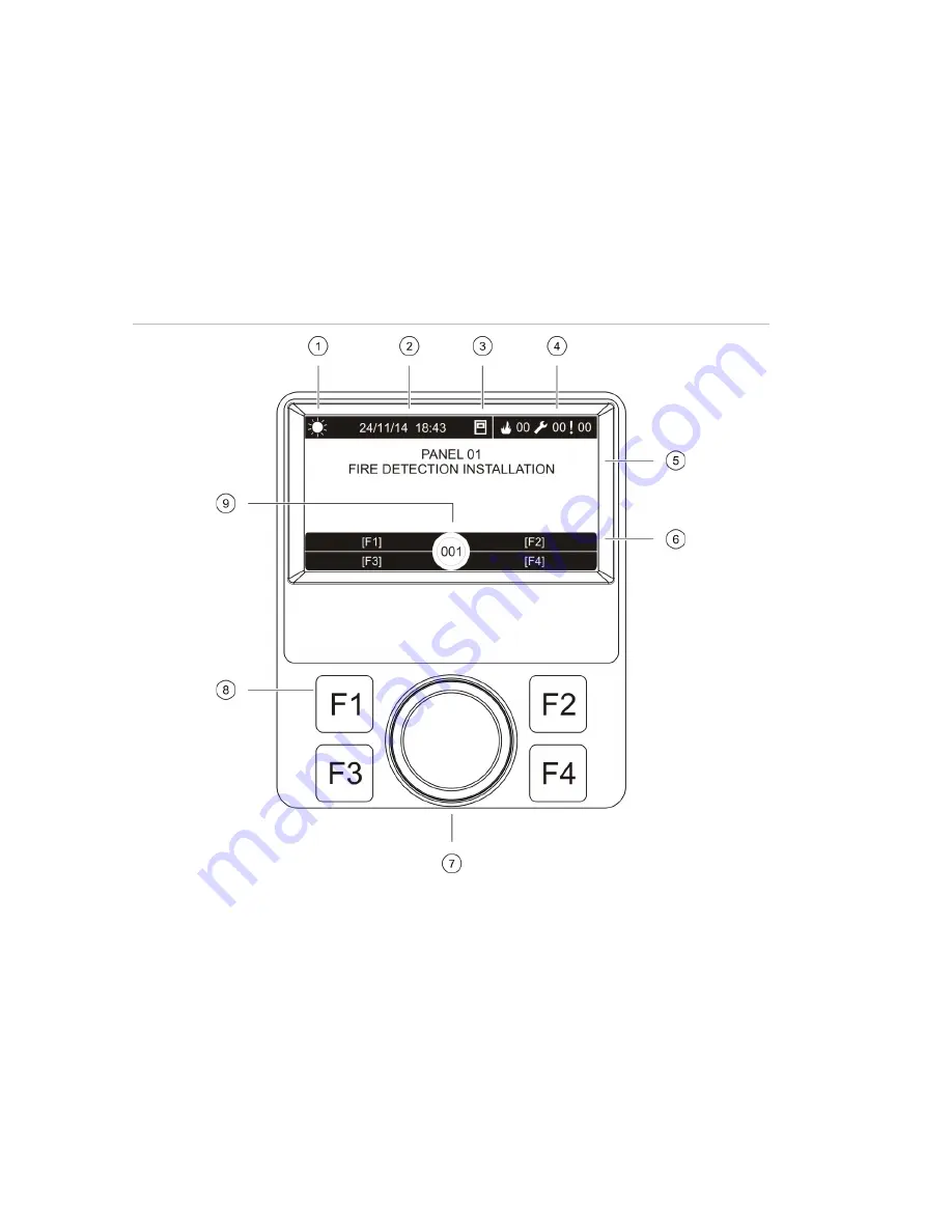
LCD controls and indicators
Figure 3: LCD controls and indicators
1. Day/night mode indicator
2. System date and time (and active fire routing delay or extended fire routing delay countdown)
3. Control panel network status (stand-alone, networked, repeater)
4. Current alarm, fault, and condition events counter
5. Message display area
6. Soft keys (menu options linked to function buttons F1, F2, F3, and F4)
7. Jog dial
8. Function buttons F1, F2, F3, and F4
9. Local control panel ID (in a fire network)
Summary of Contents for ZP2 Series
Page 1: ...ZP2 Series Installation Manual P N 00 3251 501 0003 04 ISS 04MAY15...
Page 6: ...iv ZP2 Series Installation Manual...
Page 20: ...Chapter 1 Introduction 14 ZP2 Series Installation Manual...
Page 114: ...Chapter 3 Configuration and commissioning 108 ZP2 Series Installation Manual...
Page 128: ...Chapter 5 Technical specifications 122 ZP2 Series Installation Manual...
Page 142: ...Appendix C Menu maps 136 ZP2 Series Installation Manual...
Page 148: ......


