background image

Introduction 

This Manual

This manual describes the operation
and programming of the Illusion 120
and Illusion 240 lighting desks. 

The operating software and
functionality of the two desks is the
same. Where the Illusion 240 differs
from the Illusion 120, this will be
indicated in parentheses, eg The
Illusion lighting desk has 120 (240)
channels of control.

This chapter contains a general
overview of the desk followed by a
brief description of the front panel
controls and displays, and details of
layout and content of the monitor
screen.

The quick start tutorial chapter is
provided to help you get the desk up
and running quickly and lead you
through the basic functions on the
desk.

For a more detailed description of each 
of the desk functions (setup,
memories, submasters, cueline etc.)
refer to the appropriate chapter(s) in
the manual. 

The manual concludes with chapters
on the Super User functions, other
features and the technical specification 
of the desk.

Conventions

Throughout this manual the following
conventions are used.

References to controls, buttons and
lights on the front panel appear in
capital letters, for example:

GRAND MASTER, GO, PAUSE.

Data entry via the numeric keypad and
associated keys is shown in bold type,
for example:

1 @ 50 ENTER

Options and fields which appear on the 
monitor screen are shown in italics, for
example:

Floppy Disk, Illumination, Desk Setup.

The colours specified in this manual for 
various items displayed on the monitor
screen refer to those defined in the

Normal

 display scheme. 

If a diffferent display scheme is
selected, the colours displayed on the
monitor may be different to those
specified in this manual.

1 - 1 

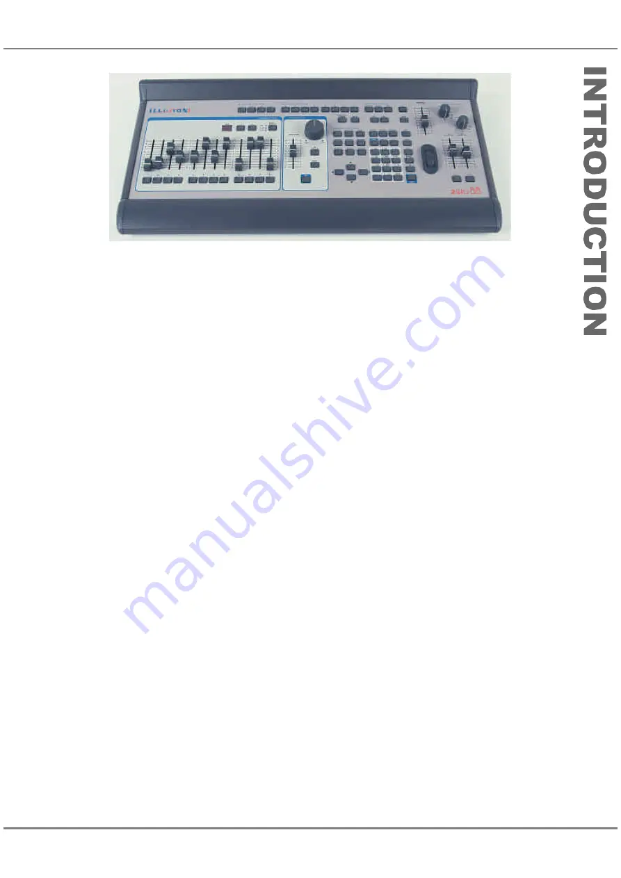
Figure 1 - 1: The Illusion Lighting Desk

Summary of Contents for ILLUSION 120

Page 1: ...ILLUSION 120 240 OPERATING MANUAL...

Page 2: ......

Page 3: ...to comply with the limits for a Class A digital device pursuant to part 15 of the FCC rules These limits are designed to provide reasonable protection against harmful interference when the equipment i...

Page 4: ...nel Data Window 4 8 5 Memories Introduction 5 1 Memories Common Data 5 2 Scene Memory 5 2 Multi Part Scene Memory 5 2 Chase Memory 5 2 Sound to Light Memory 5 2 Ripplesound Memory 5 2 All Fade Scene 5...

Page 5: ...Auxiliary Controls 10 2 Clear All 10 3 Reset Desk 10 3 Set Date and Time 10 3 Lock Desk Function 10 4 Exiting Super User Mode 10 4 11 Other Features Introduction 11 1 DMX Output Screen 11 2 DMX Patch...

Page 6: ...Contents...

Page 7: ...ons setup memories submasters cueline etc refer to the appropriate chapter s in the manual The manual concludes with chapters on the Super User functions other features and the technical specification...

Page 8: ...the Memories or Cueline screens Tracking If Tracking is enabled only changes made to the channel data are recorded into the memories Otherwise all channel values are recorded into the memory Memory S...

Page 9: ...master PAGE UP and PAGE DOWN buttons are used to select the current Submaster page 1 9 1 20 PAGE DISPLAY The current submaster page is indicated on the seven segment PAGE Display Playback X Controls M...

Page 10: ...e a step from a chase memory GROUP BUTTON This button is used in conjunction with the numeric keypad to select a pre defined group of channels CURSOR BUTTONS These four buttons are used to move around...

Page 11: ...memory DRIVE BUTTON This button is used to select the drive of a chase memory STEP AND STEP BUTTONS These buttons are used to select a required step when programming or editing a chase sound to light...

Page 12: ...outputs of the brightness channels Pressing the DBO button toggles between DBO active all brightness channels at zero and DBO not active normal desk outputs The red light in the DBO button flashes wh...

Page 13: ...t value of zero is displayed as rather than 0 For scroller channels if the output value is an exact frame value it is displayed as Fn otherwise the actual percentage or DMX value is displayed Output v...

Page 14: ...e field will scroll through the available options Where appropriate right clicking on a selected item or window will bring up a menu of options This allows certain functions eg programming memories to...

Page 15: ...the memories using the Playback X controls and outputting data from submasters Finally it gives a summary of how memories can be edited and played back from the Cueline screen Before starting a new li...

Page 16: ...the level s of the selected channels 1 wheel 5 THRU 10 wheel 20 AND 30 wheel The mouse can also be used to select channels by left clicking on the channel number in the CDW selected channels are show...

Page 17: ...return to memory 1 Playback Using Submasters The Submasters can be used to playback loaded channel data see earlier or transferred memories Transferring a Memory onto a Submaster 1 Select a programmed...

Page 18: ...ect the cue to be edited using the cursor keys or mouse 2 Position the mouse pointer on Part 1 Right click and select the Edit Live or Edit Blind option from the menu The Channel Data Window is displa...

Page 19: ...k file utilities copying and formatting disks Illumination Used for setting the desk lamp brightness Display Scheme Used for setting the preferred display scheme on the monitor Reports Used for genera...

Page 20: ...screen and contains a list of showfiles found in the top directory plus any other directories 5 Select the required load option using F4 Use the cursor keys or the mouse to select the required showfi...

Page 21: ...is read 4 Use the cursor keys or mouse to select the required memory to be loaded Move to the Load As Memory column and enter the required destination memory number 5 Repeat step 4 for each memory to...

Page 22: ...select the OK button in the window Delete F4 This option allows you to delete a directory or file on the floppy disk 1 Use the cursor keys to select the directory or file to be deleted 2 Select the De...

Page 23: ...tion Illumination The Desk Lamp Brightness can be adjusted as follows Select Illumination from the Setup options Move to the Desk Lamp Brightness field then adjust the brightness using the wheel or by...

Page 24: ...The report is divided into the following sections Desk Defaults Channel Setup Auxiliary Setup Groups Remote Switches and Tracking Each section may be included or excluded from the report Memories Thi...

Page 25: ...button value REMOTE SWITCHES Enables or disables remote switches CHANNEL DATA WINDOW Selects bargraphs or numerics only CHANNEL DATA DISPLAY Sets the Channel Data Display to the required height RECOV...

Page 26: ...ash Button CHASE TRIGGER LEVEL The default chase trigger level MACRO TRIGGER LEVEL The default macro trigger level Playback X Defaults TIME INPUT Defines the time input mode for Playback X Real SMPTE...

Page 27: ...address is already used a warning message is displayed Patching Channels 2 1 Select the channel to be patched using the cursor keys or mouse 2 Using the mouse left click on the required DMX address in...

Page 28: ...e data entered is valid the channel table is updated If the data is invalid eg a channel number entered is already associated with another channel a warning message is displayed To remove an associati...

Page 29: ...Illusion 240 there is also an Autopatch In function which allows the Illusion desk channels to be patched to DMX In channels in a single operation This is indicated by the additional Autopatch In tab...

Page 30: ...ched using the cursor keys or mouse 2 Using the mouse left click on the required DMX address in the colour coded DMX map on the screen 3 If the DMX address entered is valid the auxiliary table and DMX...

Page 31: ...s to scroll up or down the table or use the mouse The highlight bar moves to the selected switch 3 Move to the right hand column of the table using the cursor keys or the mouse 4 Use the ENTER key or...

Page 32: ...Window or press F8 on the front panel or keyboard NOTES Desk Setup While the Desk Setup Window is displayed the screen function keys F1 F8 are disabled Therefore it is not possible to display any of t...

Page 33: ...der If the CDW is opened using the CHANNEL or GROUP button from the Memories Submaster Cueline DMX Output or DMX Patch screen the header contains the words Edit Live Channel Data and soft buttons labe...

Page 34: ...nd if the current value is equal to the programmed value Editing Live unprogrammed channels are grey Programmed channels are yellow when the programmed value is equal to the current value otherwise gr...

Page 35: ...played in the CDW when the ENTER or ON key is pressed the wheel is moved or the mouse is used to adjust the level s The new channel levels are output live on the DMX if the channel data is being edite...

Page 36: ...ripplesound memory the channel data for the first step is used If the memory specified is a multi part scene the programmed channels from all the programmed parts of the memory are combined and then...

Page 37: ...and associated keys as follows Select the required channel s then enter followed by the frame number and ENTER For example CHANNEL X frame no ENTER CHANNEL X AND Y frame no ENTER CHANNEL X THRU Y fra...

Page 38: ...scription of the group in the Group Info field if required then select the OK button in the window If the specified group is unprogrammed the channel data is saved into the group and the popup window...

Page 39: ...up and return to the CDW Viewing Group Data The selected channels and their corresponding levels in a programmed group can be viewed by generating the Desk Setup Report see the Reports section in chap...

Page 40: ...close the window Closing the Channel Data Window The CDW is normally closed using the Close button in the header by pressing F8 or by saving the channel data to a specified memory submaster or group...

Page 41: ...are affected Memory Storage Limits The desk has a maximum capacity of 400 memories The different memory types require different amounts of memory A Scene memory uses one memory block A Multi Part Scen...

Page 42: ...r of steps maximum 99 each containing a set of channel data It also has the following modifiers Direction The order in which the steps are output forwards backwards or ping pong Attack The transition...

Page 43: ...are recorded as full memories Unprogramming Channels The ability to unprogram channels is only applicable to partial memories When Tracking is enabled or Multi Part Scene memories are being programmed...

Page 44: ...he edited memory is changed subsequent memories are not modified Playback of Memories in Tracking Mode When memories are played back in ascending numerical order then those channels not specifically p...

Page 45: ...ypes is as follows For all memory types the memory number type information text trigger delay times fade times and dwell time are displayed on the screen For Chase memories the number of chase steps i...

Page 46: ...IT LIVE or EDIT BLIND button on the front panel or right click and select the Edit Live or Edit Blind option from the menu This opens the Channel Data Window CDW 7 Set the channel levels to the requir...

Page 47: ...the menu The Channel Data Window is closed 12 Repeat steps 5 10 for each part of the memory to be programmed Display of Multi Part Scenes in the Channel Data Window When part of a multi part scene is...

Page 48: ...ption via the soft button in the CDW header or F4 see notes at end of this section 3 Press the SAVE STEP button on the front panel or select the Save Step button in the CDW The channel data is saved i...

Page 49: ...p is deleted and the Channel Data Window shows the previous step except if step 1 is deleted in which case it shows the new step 1 NOTES Build and Non Build Chases When programming or editing a chase...

Page 50: ...To save the complete memory data into the currently selected memory press the SAVE button on the front panel or right click in the CDW and select the Save option from the menu The Channel Data window...

Page 51: ...the window If the destination memory is unprogrammed the channel data is saved into the memory and the popup window is closed If the destination memory is already programmed a warning message is disp...

Page 52: ...ls which have been changed are saved into the step being edited any outputs originating from submasters or Playback A B are not saved Save Excluding Submasters This option is the same as Save except a...

Page 53: ...cancel the operation and close the window Undoing an Accidental Save If channel data is accidently saved to a memory or submaster it is possible to reverse the save operation using the UNDO EDIT butto...

Page 54: ...annel data are visible in the Channel Data Window and appear live on the outputs Editing Memories Blind When a programmed memory is selected and the EDIT BLIND button is pressed the selected memory be...

Page 55: ...n 4 steps long the channel data in the extra steps in the sound to light memory are set to zero if Tracking is disabled or zero and unprogrammed if Tracking is enabled Chase to Ripplesound The channel...

Page 56: ...a valid source memory is entered the source memory will be copied into the currently selected memory and the Copy window closed If the source memory number specified is invalid or the source memory i...

Page 57: ...hannel Data Window is opened To preview other memories in the memory stack use the left and right arrow keys or click on the Previous or Next buttons in the CDW header To exit Preview mode press the P...

Page 58: ...Select the OK button in the Transfer Window to complete the transfer operation NOTES Transferring Memories to Submasters Multi Part Scenes cannot be transferred onto submasters An error message is di...

Page 59: ...adjusted by the user It is possible to specify a start time which would overlap a previous memory and to program memories in a non chronological order although this is not recommended practice A memor...

Page 60: ...Three soft buttons are also provided on the Memories and Cueline screens to play pause and reset the timecode signal External Time Source When the time source is set to External the show can only be...

Page 61: ...are used to select the required submaster page The soft buttons on the Submaster screen or the Page Up and Page Down keys on an external keyboard can also be used There is always an active page which...

Page 62: ...e page number is indicated by the seven segment display Both unprogrammed and programmed submasters are shown in the table A yellow highlight bar is displayed on the submaster which is currently selec...

Page 63: ...m full to zero ATTRIBUTE TRIGGER LEVEL This field shows the value at which attribute and scroller channels are triggered when the submaster is raised CHASE TRIGGER This field shows the method of trigg...

Page 64: ...the table or Press the SUBMASTER button on the front panel enter the required submaster number eg 2 3 for page 2 submaster 3 then press the ENTER button on the front panel or Position the mouse point...

Page 65: ...f the specified memory is unprogrammed the channel data is saved into the destination memory and the popup window closed If the specified memory is already programmed a warning message is displayed Se...

Page 66: ...ase memory transferred onto it 2 Move to the Chase Trigger field Select the required trigger Transfer Fader Level Flash Button The differences in output for the different triggers are covered later in...

Page 67: ...nnot be edited Select a programmed submaster then press the PREVIEW button on the front panel or right click and select the Preview option from the menu The light in the PREVIEW button is illuminated...

Page 68: ...then select the OK button in the Copy Window If a valid submaster is entered the data associated with the source submaster is copied into the currently selected submaster and the Copy Window closed O...

Page 69: ...cial column for the corresponding submaster Otherwise an error message is displayed Editing a Macro Trigger This is the same as programming a macro trigger except that the macro number and macro trigg...

Page 70: ...ls in the channel data or memory are triggered when the submaster level reaches the attribute trigger level specified for the submaster The time taken to fade up down the channel data or memory is gov...

Page 71: ...e The outputs do not change Triggering Chase Memories on Submasters When a chase memory is transferred onto a submaster it can be triggered ie made to run in a number of ways as described below TRANSF...

Page 72: ...tomatically triggered to their programmed levels All other brightness channel data being output on submasters Playback X and Playback A B is reduced to zero except for any excluded channels being outp...

Page 73: ...n the Memories screen is reflected on the Cueline screen and vice versa Jumps Loops and Macro Triggers can be programmed into the Memory Stack if required from either the Memories or Cueline screens T...

Page 74: ...Auto as programmed in the loop On the Cueline screen the jump and loop information is displayed in the Special track A jump is shown as Jump To n where n is the cue number to jump to All the cues cont...

Page 75: ...on from the menu or right click and select the Jump To option A popup window is displayed 3 Select the Clear button in the window The popup window is closed and the jump data is removed from the Memor...

Page 76: ...ck and select the Loop option The Edit Loop Window is displayed 3 Select the Clear button in the window The window is closed and the loop data is removed from the corresponding memories in the Memorie...

Page 77: ...ect the Trigger Macro option The Edit Macro Trigger Window is displayed 3 Select the Clear button in the window The window is closed and the macro data is removed from the corresponding memory in the...

Page 78: ...the trigger for the next memory is At Time the CUELINE will jump to the start of the memory and begin running through it when the time as shown by the clock in the Information Bar equals the programme...

Page 79: ...t bar moves automatically to the next programmed memory when the GO button is pressed This is known as auto increment The outputs fade to the next memory according to its programmed transition times I...

Page 80: ...s pressed If the trigger is automatic the Cueline will start running through the first memory NOTES Memories Screen Display Mode When playing back the Memory Stack with the Memories screen on display...

Page 81: ...fade times can be controlled independently by the FADE TIME A and FADE TIME B controls on the front panel Memories can be manually loaded onto the A and B MASTERS or loaded automatically each time eit...

Page 82: ...y will be loaded onto the B MASTER automatically 4 Move the A MASTER back to zero and the B MASTER to full The outputs will crossfade between the two memories The next memory will be loaded onto the A...

Page 83: ...ry data or the memory stack on the Cueline screen are reflected in the Memories screen and vice versa To use the functions available on the Cueline screen the desk must have a mouse connected and pref...

Page 84: ...IN ZOOM OUT GO PREVIOUS PAUSE GO DISPLAY MODE The Zoom In and Zoom Out buttons in conjunction with the scroll bar allow different parts of the Cueline screen to be viewed at various magnifications Th...

Page 85: ...uired 5 Select the OK button in the Window The New Cue Window is closed and a warning window opened indicating that the channel data for the cue is currently at zero 6 To edit the channel data for the...

Page 86: ...e cue to be edited Five red handles shown as squares are displayed in the Part 1 Track or appropriate tracks for programmed parts of a multi part scene 2 To adjust a delay or fade time left click on t...

Page 87: ...t the Preview option from the menu The CDW is displayed To preview other cues use the left and right arrow keys or click on the Previous or Next buttons in the CDW header To exit preview mode press th...

Page 88: ...buttons allow the Cueline or part of the Cueline to be viewed at a range of magnifications The highest magnification displays approximately 12 seconds of Cueline the lowest approximately 1 hour 40 min...

Page 89: ...n the monitor containing the following options Clear Memories Renumber Memories Clear Submasters Clear Auxiliary Controls Clear All Reset Desk Set Date and Time Lock Desk The software version number a...

Page 90: ...er the start memory number in the field provided Select the required increment 0 1 0 2 0 5 1 2 5 or 10 Select the Renumber button in the window A popup window is displayed indicating that the renumber...

Page 91: ...Desk option from the Super User screen A confirmation window is displayed Select the OK button in the window to confirm the operation Set Date and Time This option allows the date and time to be set...

Page 92: ...of the screen Unlocking the Desk 1 Select the Lock Desk option from the Super User screen The Lock Desk Window is displayed 2 Enter the 4 digit code which was used to lock the desk then select the Un...

Page 93: ...ng features and miscellaneous items which are available on the Illusion desk DMX OUTPUT SCREEN DMX PATCH SCREEN AUXILIARY OUTPUTS TOPSET MACROS ENTERING CHANNEL VALUES ENTERING TEXT ENTERING TIMES DMX...

Page 94: ...The text in each DMX channel box shows the desk channel and auxiliary control patching as follows Cn Desk Channel n is patched to the DMX channel An Auxiliary Control n is patched to the DMX channel...

Page 95: ...wn the required AUX CONTROL button on the front panel The output on the corresponding DMX channel fades from the off value to the on value in the fade on time and then remains at the on value while th...

Page 96: ...r output values in red text Adjusting Topset Values 1 Press the TOPSET button on the front panel The Topset Window is displayed on the monitor screen This window shows the current output value and the...

Page 97: ...button sequence for the macro by pressing the front panel buttons in the required order As each front panel button is pressed its name is added to the end of the list in the Edit Macro Window 4 To en...

Page 98: ...Window is closed and the selected macro is run Triggering Macros Macros can be triggered from the Memory Stack when a memory is triggered see chapter 7 for further details Macros can also be triggere...

Page 99: ...NNEL 1 255 ENTER 255 Single Digit Direct Action Enter a tenth of the required percentage value as a single digit The command is processsed after the digit is entered The values are displayed as a perc...

Page 100: ...n in the format mm ss t Examples 0 5 ENTER 0 5 seconds 3 ENTER 3 0 seconds 12 4 ENTER 12 4 seconds 1 30 0 ENTER 1 minute 30 0 secs 2 34 5 ENTER 2 minutes 34 5 secs DMX In If a cable containing a DMX s...

Page 101: ...10V Connections Tip Left Channel Ring Right Channel Sleeve 0V Signal Ground Remote Switches 8 pin DIN connector providing 6 remote switches common ground Connections Pin 1 5V Pin 2 Remote Switch 1 Pi...

Page 102: ...drive 3 5 PC compatible formatted to 1 44Mb HD DS Printer PC compatible parallel port Serial Port 15 pin D non standard Mouse mini DIN connector PS 2 Keyboard mini DIN connector PS 2 Video Output 15 p...

Page 103: ...User Notes 13 1 Figure 13 1 Illusion Lighting Desk...

Page 104: ...13 2 User Notes...

Page 105: ......

Page 106: ...Zero 88 Lighting Ltd Tel Fax e mail Web 44 0 1633 838088 44 0 1633 867880 sales zero88 com www vari lite com 24 hour answerphone...

Reviews: