background image

F

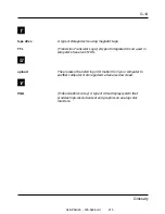
flash EPROM

A type of memory device that is usually used to store system
BIOS code. This code can be replaced with updated code from a
floppy disk, but is not lost when the computer is powered off. See
also EPROM and ROM.

floppy disk drive

See disk drive.

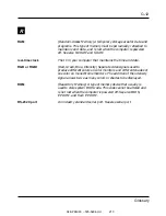
format

The process used to organize a hard or floppy disk into sectors so
it can accept data. Formatting destroys all previous data on the
disk.

G

G

(Gigabyte) 1,073,741,824 bytes. See also byte.

H

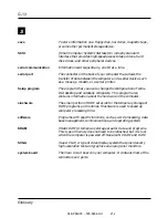
hard disk drive

See disk drive.

hardware

The physical parts of your computer, including the keyboard,
monitor, disk drives, cables, and circuit cards.

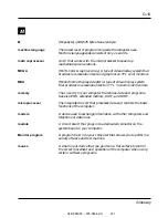
HGC

(Hercules

®

Graphics Card) A type of video display system that

provides low- or medium-resolution text and graphics on TTL
monochrome monitors.

04/APRIL/93 – 595-5484-UU

208

G-7

Glossary

Summary of Contents for z-server lt

Page 1: ...Z S E R V E R L T Z E N I T H D A T A S Y S T E M S A B u l l C o m p a n y U s e r s G u i d e 04 APRIL 93 595 5484 UU 1 ...

Page 2: ...on Printed in the United States of America This material may be reproduced by or for the U S Government pursuant to the copyright license under the clause at DFARS 252 227 7013 Oct 1988 or if provided under a contract or subcontract with NASA or a civilian agency of the Government this material may be reproduced in accordance with the provisions of the contract or subcontract with Zenith Data Syst...

Page 3: ...Chapter 3 Configuring Your System Chapter 4 Upgrades and Options Chapter 5 Problem Solving Appendix A Keyboards Appendix B Memory Configurations Appendix C Option Boards Appendix D Devices Safety Notices Glossary Equipment Log 04 APRIL 93 595 5484 UU 3 ...

Page 4: ...Chapter 1 Introduction Contents Organization 1 1 Notational Conventions 1 3 Introduction ...

Page 5: ...hapter 3 Configuring Your System Tells you how to configure the system and provides instructions for running the Setup program and the EISA Configuration Utility ECU Chapter 3 also tells you how to use jumpers to set specific operating parameters Chapter 4 Upgrades and Options Provides you with instructions for upgrading your system Chapter 5 Problem Solving Provides you with helpful information f...

Page 6: ...option board jumpers Appendix D Devices Explains the use of peripheral device jumpers Glossary Defines the standard acronyms and technical terms used in this manual Index Includes important terms arranged in alphabetical order for quick reference Equipment Log Provides you with a sample equipment log for documenting the system configuration and updates 1 2 Introduction ...

Page 7: ...d as RETURN and CARRIAGE RETURN CTRL ALT Two or three key names separated by plus sign s indicate multiple key entries For example CTRL ALT DEL means hold down the CTRL and ALT keys and press the DEL key The special notices listed below are used throughout this manual to emphasize specific information Warning Warning indicates a hazard that can cause serious personal injury or death if the hazard ...

Page 8: ...quipment or data is present if the user does not take the necessary precautions recommended by the Notice Note Notes are used to identify or amplify a point to the reader A Note may be used to emphasize a recommended sequence of steps 1 4 Introduction ...

Page 9: ...dule 2 3 Memory 2 3 FLASH ROM 2 3 Real Time Clock Calendar 2 4 Bus Master I O Expansion Slots 2 4 Keyboard and Mouse Interface 2 4 Serial Ports 2 4 Parallel Port 2 4 Video 2 5 System Keylocks 2 6 Security Loophole 2 7 04 APRIL 93 595 5484 UU 11 Features ...

Page 10: ...I O ports and up to 128M of onboard memory An onboard EISA Bus Master dual channel SCSI II controller board that supports two channels A CPU module connector that supports a number of different CPU module types A CPU module is included with the system An optional memory module that supports up to a maximum of 256M of memory 04 APRIL 93 595 5484 UU 13 2 1 Features ...

Page 11: ...rating environments including MS DOS OS 2 Novell NetWare Banyan Vines Microsoft LAN Manager SCO Unix Other Unix systems Microsoft Windows NT The Z SERVER LT is available with floppy disk drives hard disk drives tape drives network boards multiport boards and a CD ROM drive 04 APRIL 93 595 5484 UU 14 2 2 Features ...

Page 12: ... memory of 128M The optional memory expansion module has eight SIMM sockets that can accommodate 2M 4M 8M 16M or 32M SIMMs SIMMs must be installed in pairs of the same size for a maximum expansion memory of 256M Total system memory is the combined total of system board memory and optional expansion memory The maximum total system memory is 384M FLASH ROM The 256K FLASH ROM read only memory is divi...

Page 13: ... CPU DMA and bus masters Keyboard and Mouse Interface The keyboard and mouse interface with the system control processor through bi directional ports and connect to the system board through mini DIN connectors Serial Ports The system has two 9 pin male D type serial connectors These are located at I O address COM1 and COM2 The serial ports are fully programmable and support asynchronous communicat...

Page 14: ...GA modes BIOS compatibility with VGA EGA CGA Hercules and MDA 512K video memory upgradeable to 1M 16 bit bus for high speed display memory access Internal VESA video feature connector Resolution up to 1024 768 256 Note SVGA drivers may be required to use the high performance video modes 04 APRIL 93 595 5484 UU 17 2 5 Features ...

Page 15: ...le front panel that provides access to the peripheral bays power switch system reset button and keyboard and mouse lock The keys to the front panel lock are taped to the inside of the front panel F4 2 OM02152 04 APRIL 93 595 5484 UU 18 2 6 Features ...

Page 16: ...s also a metal loop protruding through the slot in the back of the side cover that can be padlocked to prevent entry into the system A padlock is not shipped with the system F4 3 OM02148A 04 APRIL 93 595 5484 UU 19 2 7 Features ...

Page 17: ...ng the Onboard Video Controller 3 19 Write Protecting Floppy Drives 3 19 Resetting the NVRAM and RTC 3 20 Clearing the Password 3 21 Selecting the SIMM Size for Bank 0 3 21 Selecting the SIMM Size for Bank 1 3 22 Increasing the Video Buffer Size 3 23 Flash Memory Reprogramming Jumper 3 24 Remapping Onboard Video Controller Address 3 25 System Configuration Settings 3 26 Adaptec AIC 7770 SCSI Host ...

Page 18: ...to be run unless you change the password or security features add adapter boards or upgrade your system Note Since the configuration information stored in the ECU overrides the configuration information stored in the Setup utility It is strongly recommended that you only use the Setup utility for the following two reasons 1 If the floppy disk drive is disabled and you want to enable the floppy dis...

Page 19: ...g the POST power on self test the settings are checked against the actual hardware configuration If they do not agree the POST generates an error message It is not recommended to use Setup to make configuration changes Changes or corrections to your configuration should be done using the ECU The changes then will be written to the Setup utility Accessing Setup Enter Setup by pressing F1 when the P...

Page 20: ...tem Time The setting contains three fields hours minutes and seconds The new time takes effect immediately you do not have to reboot the system System Date The setting contains three fields month day of the month and year The new date takes effect immediately you do not have to reboot the system Language In addition to English Setup can be displayed in French German Italian and Spanish Onboard Flo...

Page 21: ...tem environment and applications 640 480 Refresh Rate Select the refresh rate that your video display vertical sync supports when in 640 480 mode 800 600 Mode Refresh Rate Select the refresh rate that your video display vertical sync supports when in 800 600 mode 1024 768 Mode Refresh Rate Select the refresh rate that your video display vertical sync supports when in 1024 768 mode Video Font This ...

Page 22: ...creen The next time the system boots it will prompt you for the password To change the password enter the following at the Enter Password prompt oldpassword newpassword newpassword To remove the password enter the following at the Enter Password prompt password To disable the password facility set the clear password jumper on the system board Refer to the Jumper Configurations section later in thi...

Page 23: ...o 640K Base Memory The setting which cannot be changed displays the size of the base memory in kilobytes If there is a failure in base memory this size will differ from what was set in the Setting Base Memory Above 512K option Extended Memory The setting which cannot be changed displays the amount of memory in the system above 1M The memory includes SIMMs on the system board and memory on the memo...

Page 24: ...e appropriate speed to copy the system input and output to serial port 2 Select Disabled if the option is not in use since it effects overall performance or if you do not intend to use console redirection CPU Speed Set the CPU speed set to Fast for most applications If the speed is set to Slow the internal cache and any secondary cache is disabled and the system effectively runs like an 8MHz IBM E...

Page 25: ...esses where you want to map the start of the onboard video BIOS Some software expects to find certain video attributes at the lower address range C0000H Shadow C0000 to C7FFF When enabled the system copies the address which can be cached to 32 bit RAM memory Shadow C8000 to CFFFF When enabled the system copies the address which can be cached to 32 bit RAM memory Shadow E0000 to E7FFF When enabled ...

Page 26: ...y The ECU also maintains the Setup configuration which is stored in the battery backed memory of the RTC real time clock This means that when you exit the ECU the battery backed memory and the FLASH memory will agree with each other If the diskette is write enabled when you configure your system the ECU automatically creates an SCI system configuration information file that you can use to restore ...

Page 27: ...ting the system configuration disk into floppy disk drive A and reboot the system 4 Follow the ECU main menu prompts To select an item from the menu use and to highlight the item and press ENTER If you are using a mouse point to an item and then double click the left button to select it 5 Select Learn about configuring your computer from the ECU main menu if you need more information 6 Select Acce...

Page 28: ...nstandard video displays and when you have redirected the console to one of the onboard serial ports F Automatic configuration mode Configures the system by auto adding EISA add in boards and using valid flash memory for the configuration information If the flash memory is invalid the SYSTEM SCI file will be used to obtain the configuration information H High resolution display Sets the display mo...

Page 29: ...Utilities One of the selections from the main menu of the ECU Access System Utilities lets you set system passwords and other configuration settings Some of these settings are also accessible through Setup Password Utilities Power on Password If you set a password in this utility it must be entered each time the system boots before you can access the system To disable the password facility set the...

Page 30: ...rd prompt oldpassword newpassword newpassword To remove the password enter the following at the Enter Password prompt password Keyboard Password This selection lets you enter a password for the keyboard To enter a password follow the instructions on the screen You must enter the password a second time for verification After you have installed a keyboard password you can lock the keyboard with the ...

Page 31: ...l rated speed of the CPU Speaker The speaker selections let you turn the system speaker on or off When you reboot the system the state of the speaker will revert to what you specified in Setup Cache The cache selections let you turn on or off the system s caching capabilities both the internal cache of the CPU and the external cache if installed When you reboot the system the system caching will r...

Page 32: ...e jumper from its current location Position the jumper over the two pins for the desired setting and press it onto the pins Be careful not to bend the pins The following figure shows the location of the system board jumpers and the orientation of jumper pins 1 2 and 3 The following table lists the system board jumpers and their factory default settings F3 1 01001A E0392 E0391 E0390 E0292 E0291 E02...

Page 33: ...90 Password Enable 1 to 2 Clear 2 to 3 E0391 Memory bank 0 Standard SIMMs 1 to 2 16 32M SIMMs 2 to 3 E0392 Memory bank 1 Standard SIMMs 1 to 2 16 32M SIMMs 2 to 3 E0720 Video memory Buffer size 512K 1 to 2 Buffer size 1M 2 to 3 E0721 Flash memory Write enable 1 to 2 Write disable 2 to 3 E0722 Video controller Starting address 03C3H 1 to 2 I O address Starting address 46E8H 2 to 3 Default settings ...

Page 34: ...that the flash memory boot jumper E0191 is on pins 1 and 2 default 4 Replace the covers and connect the power cord to the system 5 Insert the Flash memory update diskette Power on the system and wait for the Flash memory utility menus 6 Reprogram the flash memory 7 Run the ECU to configure the system as described earlier in this chapter 04 APRIL 93 595 5484 UU 39 3 17 Configuring Your System ...

Page 35: ...ff the system and remove the covers as described in the Upgrades and Options chapter 2 Ensure that the flash memory jumper E0721 is on pins 1 and 2 default 3 Move the flash memory boot jumper E0191 to pins 2 and 3 4 Insert the flash memory update disk in drive A and power on the system The recovery process is automatic Note Since there is no monitor display and the keyboard is disabled during the ...

Page 36: ...pins 2 and 3 3 Replace the covers and power on the system 4 Run the ECU to specify the new setting Write Protecting Floppy Drives Jumper E0291 is used as a security device that controls writing to disks in the system floppy drives For example it can be used to prevent users from copying information from the system hard disk drives to a floppy disk To write protect a floppy disk with this jumper pe...

Page 37: ...ions chapter 2 Move the NVRAM jumper E0292 to pins 2 and 3 3 Ensure that the flash memory jumper E0721 is on pins 1 and 2 default 4 Connect the power cord to the system power on the system and wait for the POST to complete This will automatically reprogram the NVRAM and RTC to their default settings 5 Power off the system and remove the power cord 6 Move the NVRAM jumper E0292 to pins 1 and 2 7 Re...

Page 38: ...s chapter and power on the system 7 To specify a new password run the ECU as described earlier in this chapter Selecting the SIMM Size for Bank 0 Jumper E0391 is used to select the amount of SIMM memory size for bank 0 The default position for this jumper is set to STD standard mode pins 1 and 2 when bank 0 contains 2M 4M and 8M SIMMs For 16M and 32M SIMMs this jumper must be moved to pins 2 and 3...

Page 39: ...rd mode pins 1 and 2 when bank 1 contains 2M 4M and 8M SIMMs For 16M and 32M SIMMs this jumper must be moved to pins 2 and 3 1 Power off the system and remove the covers as described in the Upgrades and Options chapter 2 Move the SIMM 1 jumper E0392 to pins 2 and 3 3 Replace the covers and power on the system 04 APRIL 93 595 5484 UU 44 3 22 Configuring Your System ...

Page 40: ...s as described in the Upgrades and Options chapter 2 Install four 256K 4 60 ns DRAMs Model MV 0010 in the following system board sockets U0730 U0731 U0732 and U0830 3 Move the video memory jumper E0720 to pins 2 and 3 4 Replace the covers and power on the system F3 2 01001 A 1 2 3 E0720 E0721 E0722 E0191 E0290 E0291 E0292 E0390 E0391 E0392 U0830 U0732 U0731 U0730 04 APRIL 93 595 5484 UU 45 3 23 Co...

Page 41: ...tion boards in the system you must use the ECU to modify the EISA configuration stored in flash memory Notice Ensure that the FLASH reprogramming jumper E0721 is on pins 1 and 2 default Do not change the NVRAM jumper E0292 1 Power off the system and remove the covers as described in the Upgrades and Options chapter 2 Ensure that the flash memory reprogramming jumper E0721 is on pins 1 and 2 Note I...

Page 42: ...ting address of the registers to 46E8H perform the following procedure 1 Power off the system and remove the covers as described in the Upgrades and Options chapter 2 Move the video controller I O address jumper E0722 to pins 2 and 3 to change the starting address of the I O registers to 46E8H 3 Replace the covers and power on the system 04 APRIL 93 595 5484 UU 47 3 25 Configuring Your System ...

Page 43: ...p On board Floppy Controller Enable onboard floppy controller Diskette A 3 5 inch 1 44M drive Diskette B Diskette B disabled2 Onboard IDE hard Disk Disable onboard IDE controller Onboard SCSI Controller Enabled Interrupt IRQ 11 Hard Disk Group Hard Drive 1 Disabled Hard Drive 2 Disabled Parallel Port Parallel port enabled base address 378H compatible Serial Port Group Serial Port 1 Serial port 1 e...

Page 44: ...FFFh Disabled Shadow C8000h CFFFFh Disabled Shadow E0000h E7FFFh Enabled Keyboard Control Keyboard enabled On board Mouse Control Mouse enabled Speaker Control Speaker enabled CPU Speed CPU speed FAST NumLock Boot State On at boot I O Recovery Time Enhanced Posted I O Writes Enabled Concurrent Refresh Enabled LCD Operation Disabled Scan Flash User Area Disabled Post memory Test Prompt Enabled BIOS...

Page 45: ...pter Interface Definitions Bus Release Time 60 BCLKS Data FIFO Threshold 100 SCSI Channel A Configuration Host Adapter SCSI ID 7 SCSI Bus Parity Check Enabled SCSI Selection Timeout 256 milliseconds SCSI Bus Reset at Power on Enabled SCSI Channel B Configuration Host Adapter SCSI ID 7 SCSI Bus Parity Check Enabled SCSI Selection Timeout 256 Milliseconds SCSI Bus Reset at Power on Enabled BIOS and ...

Page 46: ...ice Not Found no no no no no no no no BIOS Support Option yes yes yes yes yes yes yes yes Send Start Unit Command yes yes no yes yes no no no Initiate Sync Negotiation yes yes yes yes yes yes yes yes Enable Disconnection yes yes yes yes yes yes yes yes Maximum Sync Xfer Rate 10 0 10 0 10 0 10 0 10 0 10 0 10 0 10 0 Channel B Device ID 0 1 2 3 4 5 6 7 Error if Device Not Found no no no no no no no n...

Page 47: ...9 Removing SIMMs 4 11 Module Retaining Bracket 4 13 Removing the Module Retaining Bracket 4 13 Installing the Module Retaining Bracket 4 15 CPU Module 4 16 Installing the CPU Module 4 16 Removing the CPU Module 4 17 Memory Module 4 18 Installing the Memory Module 4 18 Removing the Memory Module 4 21 Installing Memory Module SIMMs 4 21 Removing Memory Module SIMMs 4 25 Option Cards 4 27 04 APRIL 93...

Page 48: ... an Internal SCSI Hard Disk Drive 4 36 Front Panel Cover 4 37 Removing the Front Panel Cover 4 37 Installing the Front Panel Cover 4 38 Removable Media Devices 4 38 Removing a Device 4 39 Installing a Device 4 42 Installing an Overdrive Processsor 4 45 Long 486DX 33 CPU Module 4 45 Short 486DX 33 CPU Module 4 47 04 APRIL 93 595 5484 UU 54 ...

Page 49: ... the covers before powering on your system Contact your sales representative or dealer for a list of approved optional peripheral devices Static Precautions An electrostatic discharge ESD can damage disk drives option boards and other components You can provide some ESD protection by wearing an antistatic wrist strap attach to chassis ground when handling system components Electronic devices can b...

Page 50: ...ife Antistatic wrist strap recommended Equipment Log Use the equipment log form located at the end of this manual to record the model and serial number of your system all installed options and any other pertinent information specific to your system You will need this information when configuring your system 04 APRIL 93 595 5484 UU 56 4 2 Upgrades and Options ...

Page 51: ...ce the covers before powering on the system Note If you are removing the covers after the system is set up you must first power off the system and all external devices Disconnect all external cables and unplug the system 1 The side cover on the left side of the system as viewed from the front is secured with two screws Remove the padlock if used and the screws as shown in the following illustratio...

Page 52: ... tips and gently pry the side cover loose 3 Slide the side cover backward about two inches until the tabs inside the side cover clear the slots in the chassis 4 Using both hands lift the side cover free of the chassis and set it aside 04 APRIL 93 595 5484 UU 58 4 4 Upgrades and Options ...

Page 53: ...rd Remove the six internal cover retaining screws C F4 2 OM02313 6 Open the right side of the cover until it is 90 degrees relative to the system and disengage the locking tabs B from the chassis slots A 7 Set the cover aside C A B 04 APRIL 93 595 5484 UU 59 4 5 Upgrades and Options ...

Page 54: ...dures 1 Before replacing the system covers make sure no tools or loose parts have been left inside the system chassis 2 Make sure all option boards are firmly seated in their respective slots and that all interior cables are properly connected 3 Insert the locking tabs B into the chassis slots A F4 3 OM02313A C A B 04 APRIL 93 595 5484 UU 60 4 6 Upgrades and Options ...

Page 55: ... inches beyond the back of the chassis F4 4 OM02154B 7 Slide the cover toward the front of the system so that the tabs firmly engage in the notches in the chassis frame 8 Replace the two side cover retaining screws install the padlock if used Note If your system is already set up plug the system back in reconnect the peripherals and power on the peripherals and system 04 APRIL 93 595 5484 UU 61 4 ...

Page 56: ...different sizes SIMMs can be installed in either two or four of the SIMM sockets F4 5 54840001 When you install SIMMs in the sockets on the system board you must start with socket J0550 When you remove SIMMs from the sockets you must start with the first SIMM filled socket closest to the top edge of the system board Note Only SIMMs from approved manufacturers have been tested for compatibility wit...

Page 57: ... be installed and removed in pairs 1 Power off the system and remove the covers as described earlier in this chapter Notice Observe static precautions Use an antistatic wrist strap 2 Holding the SIMM module only by the edges remove it from its antistatic package 3 With the notched edge A of the SIMM B facing towards the left edge of the system board position the SIMM at about a 45 angle relative t...

Page 58: ...ill pass through the holes in the end of the SIMMs If the SIMM does not install correctly gently spread the retaining clips just enough so that you can pull away the top edge of the SIMM and try again 5 Repeat the above steps to install the remaining SIMMs in the sockets Fill the sockets in this order J0550 J0551 J0650 and J0651 Remember that SIMMs must always be installed in pairs 6 Replace the c...

Page 59: ...ure on the metal retaining clips to release the SIMM SIMMs must always be installed and removed in pairs 1 Power off the system and remove the covers as described earlier in this chapter 2 Remove the SIMM modules one at a time in this order J0651 J0650 J0551 and J0550 F4 7 54840001 J0651 J0650 J0550 J0551 04 APRIL 93 595 5484 UU 65 4 11 Upgrades and Options ...

Page 60: ...lips F4 8 54840003 4 Carefully lift the SIMM away from the socket and store it in an antistatic package 5 Repeat the above steps to remove the remaining SIMMs 6 Replace the covers and power on the system 7 Run the ECU to configure the system as described in the Configurations chapter B A 04 APRIL 93 595 5484 UU 66 4 12 Upgrades and Options ...

Page 61: ...Use an antistatic wrist strap 2 To remove the CPU module retaining bracket While supporting the CPU module B squeeze the notched end of the module retaining bracket 2 that protrudes through the slot in the back of the chassis 3 and slide it forward through the slot near the fan and card guide support panel 1 until it stops To remove the memory module retaining bracket While supporting the memory m...

Page 62: ...is 4 Slide the memory bracket towards the front or the CPU bracket towards the back of the chassis until it comes out of the support panel Set the bracket aside 5 The CPU or memory module board can now be removed C B A 1 2 2 3 04 APRIL 93 595 5484 UU 68 4 14 Upgrades and Options ...

Page 63: ...sert the flat end of the memory module retaining bracket in the back of the chassis 2 until it stops 2 While supporting the bracket and CPU or memory module gently move the module up and down until it aligns with the slots in the retaining bracket A in the previous illustration 3 While squeezing the notched end of the bracket 2 slide this end of the bracket into the slot on the back 1 or front 3 o...

Page 64: ...ve processor 486DX2 66 CPU Module This module contains a 486DX microprocessor that operates at 66 MHz with an integrated write through 128K cache Installing the CPU Module 1 Power off the system and remove the covers as described earlier in this chapter 2 Remove the module retaining bracket as described earlier in this chapter Notice Observe static precautions Use an antistatic wrist strap 3 Remov...

Page 65: ...eplace the module retaining bracket as described earlier in this chapter 7 Replace the covers and power on the system 8 Run the ECU to configure the system as described in the Configuration Your System chapter Verify the correct CPU and cache settings for the CPU module you installed J0710 J0730 J0770 04 APRIL 93 595 5484 UU 71 4 17 Upgrades and Options ...

Page 66: ...3 Remove the CPU module from connectors J0710 J0730 and J0770 on the system board and place it on an antistatic foam pad or on a grounded workstation 4 Remove the CPU module serial number from the equipment log 5 Install a new CPU module as described earlier in this chapter before replacing the covers and powering up the system 04 APRIL 93 595 5484 UU 72 4 18 Upgrades and Options ...

Page 67: ...ule 1 Power off the system and remove the covers as described earlier in this chapter Notice Observe static precautions Use an antistatic wrist strap 2 Remove the memory module from its protective wrapper holding the module only by the edges Do not touch the module components or gold connectors 3 Record the memory module serial number in the equipment log 04 APRIL 93 595 5484 UU 73 4 19 Upgrades a...

Page 68: ...12 54840006 5 Install the module retaining bracket as described earlier in this chapter 6 Replace the covers and power on the system 7 Run the ECU to configure the system as described in the Configurations chapter J0520 04 APRIL 93 595 5484 UU 74 4 20 Upgrades and Options ...

Page 69: ...figure the system as described in the Configurations chapter 7 Remove the memory module serial number from the equipment log Installing Memory Module SIMMs Notice Use extreme care when installing a SIMM module Applying too much pressure can break the retaining clips or damage the socket slot SIMMs must always be installed or removed in pairs 1 Power off the system and remove the covers as describe...

Page 70: ...antistatic package 4 With the notched edge A of the SIMM facing towards the left edge of the module position the SIMM B at a 45 angle relative to the socket on the board and insert the bottom edge of the SIMM into the socket Press down firmly on the SIMM until it seats correctly F4 13 54840007 B C A D C B A 04 APRIL 93 595 5484 UU 76 4 22 Upgrades and Options ...

Page 71: ...SIMM does not install correctly gently spread the retaining clips just enough so that you can pull away the top edge of the SIMM and try again Note If you are installing 16M or 32M SIMMs refer to the following table and illustration for correct jumper settings on the memory module 6 After installing SIMMs reinstall the memory module as described earlier in this chapter 7 Replace the covers and pow...

Page 72: ...nd 8M 16M and 32M 2 W2 1 to 2 2 to 3 2M 4M and 8M 16M and 32M 3 W3 1 to 2 2 to 3 2M 4M and 8M 16M and 32M 4 W4 1 to 2 2 to 3 2M 4M and 8M 16M and 32M Default setting F4 14 54840008 D C B A J4 J8 J3 J7 J2 J6 J5 J1 04 APRIL 93 595 5484 UU 78 4 24 Upgrades and Options ...

Page 73: ...arlier in this chapter Notice Observe static precautions Use an antistatic wrist strap 2 Remove the memory module from the system as described earlier in this chapter and place it on an anti static surface with the SIMMs sockets facing upward and the edge connector facing you 3 Starting with the first SIMM filled socket remove the SIMM modules one at a time 4 Gently spread the metal retaining clip...

Page 74: ...atic package 6 After removing SIMMs replace the memory module as described earlier in this chapter 7 Replace the covers and power on the system 8 Run the ECU to configure the system as described in the ConfigurationS chapter B A A B C D 04 APRIL 93 595 5484 UU 80 4 26 Upgrades and Options ...

Page 75: ...f you are installing or removing an EISA option card you must run the ECU to reconfigure the system Note that for an ISA card running the ECU may not be required Also if you are installing an optional SCSI host adapter board you must first run the ECU to disable the onboard dual channel adapter before installing the optional SCSI adapter Installing an Option Card 1 Power off the system and remove ...

Page 76: ...d serial number in the equipment log 5 Set any card jumpers or switches as described in the Option Boards appendix or the documentation that comes with the option board 6 Holding the card by its top edge or upper corners firmly press the card into an expansion slot on the system board The tapered foot of the option card retaining bracket must fit into the mating slot in the expansion slot frame 04...

Page 77: ...et fits into the space that was occupied by the expansion slot cover 8 Reinstall the screw in the threaded hole Be sure to push the bracket slot up against the screw before you tighten it If this is not done the bracket may interfere with an adjacent bracket 9 If you have not installeed a SCSI host adapter board go to step 12 otherwise continue 04 APRIL 93 595 5484 UU 83 4 29 Upgrades and Options ...

Page 78: ...adapter board in slot 7 11 Connect P2 on the hard disk activity LED cable to HD LED J0190 on the system board and P1 to the SCSI host adapter board in slot 7 F4 18 54840018 12 Replace the covers power on the server and run the ECU if you have installed any EISA option cards HD LED P2 J0400 J0302 J0300 J0200 J0101 J0100 J0001 J0000 A Slot 1 Slot 3 Slot 4 Slot 5 Slot 2 Slot 6 Slot 7 Slot 8 P1 B C P3...

Page 79: ...at each end and carefully rock it back and forth until the edge connectors pull free Make sure that you do not scrape the card against other components 5 Remove the card from the expansion slot and place it in an antistatic wrapper 6 If you are replacing a board go to Installing an Option Card earlier in this chapter otherwise continue 7 Install an expansion slot cover over the vacant slot using t...

Page 80: ...lling an Internal SCSI Hard Disk Drive 1 Power off the system and remove the covers as described earlier in this chapter Notice Observe static precautions Use an antistatic wrist strap 2 Remove the 3 5 inch hard disk drive from its protective wrapper Record the drive model and serial number in the equipmentlLog 3 Set any drive jumpers or switches as described in the Devices appendix and remoce SCS...

Page 81: ...n rail are facing outward Be sure the flat side of the snap in rail is parallel to the bottom circuit board side of the hard disk drive when the snap in rail is being installed 5 Position the drive so that the plastic slide rails on each side of the drive engage the peripheral bay guide rails For drive installation sequence refer to the Devices appendix A B 04 APRIL 93 595 5484 UU 87 4 33 Upgrades...

Page 82: ... F4 20 54840028 6 Push the drive into the bay until the snap in rails lock in place F4 21 54840029 4 3 2 1 A B C 04 APRIL 93 595 5484 UU 88 4 34 Upgrades and Options ...

Page 83: ...inator is factory installed on P7 of the SCSI signal cable This terminator must remain in position P7 regardless of the number or type of SCSI devices installed F4 22 54840030 8 Replace the covers and power on the system P10 P11 P8 P9 P3 P2 P4 P5 P6 P7 P1 04 APRIL 93 595 5484 UU 89 4 35 Upgrades and Options ...

Page 84: ...efore the drive can be removed 3 Squeeze the protruding plastic snap in rails towards each other and carefully slide the drive out of the bay 4 If you are replacing a drive install the new drive as described earlier in this chapter Note Verify that all cables are seated and routed properly 5 Replace the covers and power on the system 6 Remove the drive serial number from the equipment log F4 XX 54...

Page 85: ...riate filler panels Removing the Front Panel Cover 1 Power off the systemas described earlier in this chapter 2 Unlock and open the front door until it is at an angle of 90 degrees relative to the system Gently pull the door toward you until it and the inner panel it is attached to disengage from the base panel that is attached to the system F4 23 54840023 Remove the inner panel and door from the ...

Page 86: ...ces can be installed in peripheral bays A B and C as shown in the following table Bay A 1 44M floppy always installed Bay B 1 2M floppy 1 44M floppy CD ROM SCSI add 5 Bay C 525M Tape SCSI add 2 DAT SCSI add 6 CD ROM SCSI add 5 alternate location if floppy in bay B Note If you are installing a floppy disk drive in bays A or B use the internal floppy disk drive cable s provided with the system If yo...

Page 87: ...t exposure to the laser beam do not try to open the enclosure Use of controls or adjustments or performance of procedures other than those specified in the CD ROM manufacturer s documentation may result in hazardous radiation exposure Removing a Device 1 Power off the system 2 Remove the front panel and door assembly from the system as described earlier in this chapter 3 Squeeze the protruding pla...

Page 88: ...ect the power cable and ribbon data cable 5 Each plastic snap in slide rail is attached to the device with two screws An EMI ESD grounding clip is installed on each rail under the screw head near the front of the device 04 APRIL 93 595 5484 UU 94 4 40 Upgrades and Options ...

Page 89: ...and two snap in slide rails from the device 7 Install the appropriate filler panel into the front panel 8 Replace the front panel and power on the system 9 Remove the drive serial number from the equipment log B C A 04 APRIL 93 595 5484 UU 95 4 41 Upgrades and Options ...

Page 90: ...serial number in the equipment log 4 Set any device jumpers or switches and remove the SCSI termination resistors if present Refer to Appendix D 5 Using the screws and an EMI ESD grounding clip attach a plastic snap in slide rail to each side of the device Install a grounding clip to each rail under the screw head near the front of the device See previous illustration 6 Pull the device cables forw...

Page 91: ...wer cable to the device the connector is keyed and can be inserted only one way 9 While supporting the device in front of the system connect the ribbon data cable to the device the connector is keyed and can be inserted only one way 04 APRIL 93 595 5484 UU 97 4 43 Upgrades and Options ...

Page 92: ...terminates on floppy disk drive A in bay A 10 Position the device so that the plastic slide rails on each side of the device engage the peripheral bay guide rails 11 Push the device into the bay until the slide rails lock in place 12 Remove the peripheral filler panel from the front panel by removing the two screws that hold it in place F4 27 548400031 13 Replace the front panel and covers and pow...

Page 93: ...1 Power off the system and remove the covers as described earlier in this chapter 2 Remove the CPU module from the system board and place it on an antistatic foam pad Notice Observe static precautions Use an antistatic wrist strap 3 Remove the new processor from its protective packaging 4 Align the notched corner of the new processor with pin 1 on the socket and lower the processor into place 04 A...

Page 94: ... module as described in the CPU Module section 7 Replace the covers and power on the system 8 Run the ECU and verify the correct processor was installed Save the configuration Pin 1 04 APRIL 93 595 5484 UU 100 4 46 Upgrades and Options ...

Page 95: ...Notice Observe static precautions Use an antistatic wrist strap 2 Remove the CPU module from the system board as described in Removing the CPU Module earlier in this chapter Place the CPU module on an antistatic surface F4 29 54842203 U1 1 U 8 U 7 U 3 U 2 04 APRIL 93 595 5484 UU 101 4 47 Upgrades and Options ...

Page 96: ...aight up until it is perpendicular to the socket 5 Remove the processor C from the socket being careful not to touch the pins of the device 6 Place the processor in an antistatic bag 7 Remove the new processor from its protective packaging 8 Align the notched corner D of the new processor with pin 1 E on the socket and lower the processor into place B A C D E 04 APRIL 93 595 5484 UU 102 4 48 Upgra...

Page 97: ...rasp the socket lever handle B and gently push the lever down until it snaps into the lock position 12 Install the CPU module into the system as described in Installing the CPU Module earlier in this chapter 13 Replace the covers and power on the system 14 Run the ECU and verify the correct processor was installed Save the configuration 04 APRIL 93 595 5484 UU 103 4 49 Upgrades and Options ...

Page 98: ...g 5 6 Troubleshooting Guide 5 6 Specific Problems and Corrective Actions 5 9 Power LED Does Not Light 5 9 System Cooling Fans Do Not Rotate 5 10 No Characters Appear On Screen 5 10 Characters are Distorted or Incorrect 5 11 Incorrect Or No Beep Pattern 5 12 Floppy Disk Drive Activity LED Does Not Light 5 12 Hard Disk Drive Activity LED Does Not Light 5 13 Problems with Application Software 5 14 Er...

Page 99: ... the Line Voltage in the Setting Up Guide Is AC available at the wall outlet Is the keyboard locked If the keyboard and mouse activity light are lit the keyboard and mouse are locked To unlock simply press the keyboard mouse on off push button Are all cables connected Are the CPU and memory modules fully seated and in their respective connector slots on the system board Are all the EISA ISA option...

Page 100: ...Refer to the Upgrades and Options chapter If the system has a hard disk drive is it properly formatted or defined Are all drivers properly installed For information about installing drivers see the Upgrades and Options chapter Is the power on off push button switch on the front panel in the ON position power on LED should be lit Are the configuration settings in Setup and the EISA Configuration Ut...

Page 101: ...copy Unauthorized copies often do not work Obtain an authorized copy of the software If you are running the software from a floppy disk is it a good copy If you are running the software from a hard disk drive is the software correctly installed Were all necessary procedures followed and files installed Are the correct device drivers installed Is the software correctly configured for the system Are...

Page 102: ...f the problems are intermittent there may be a loose cable dirt in the keyboard if keyboard input is incorrect a marginal power supply or other random component failures If you suspect that a transient voltage spike power outage or brownout might have occurred reload the software and try running it again Symptoms of voltage spikes include a flickering video display unexpected system reboots and th...

Page 103: ...oft boot reset Reset button Pushing the reset button clears the system memory restarts the POST and reloads the operating system Power off on Turning the power off and then on with the pushbutton switch on the front panel has the same effect as pushing the reset button except that power is halted to all peripherals This is a cold boot reset 5 5 Problem Solving ...

Page 104: ...play puts out a series of long and short beeps One short beep means the system passed POST Refer to the Error Messages section in this chapter for a list of items to check for each error code and for an explanation of the error beep codes Troubleshooting Guide Use the following step by step troubleshooting procedure to help you identify a problem This procedure leads you through the following gene...

Page 105: ...ast controls to at least two thirds of their maximum ranges refer to the documentation supplied with your video display 4 If the operating system normally loads from the hard disk drive make sure there is no floppy disk in floppy disk drive A Otherwise place a floppy disk containing the operating system files in drive A 5 Power on the system If the power LED does not light refer to Power LED Does ...

Page 106: ...h device is checked its access LED should turn on briefly Check for the following The floppy disk drive A activity LED turns on briefly If not refer to Floppy Disk Drive Activity LED Does Not Light later in this chapter If a second floppy disk drive B is installed its activity LED turns on briefly If not refer to Floppy Disk Drive Activity LED Does Not Light later in this chapter If there is a har...

Page 107: ...isk drive access LED does not light Hard disk drive access LED does not light The ECU does not boot Problems with application software Try the solutions in the order given If you cannot correct the problem contact your service representative for assistance Power LED Does Not Light Check the following Is the system operating normally If so the power LED is probably defective Are there other problem...

Page 108: ...t panel power on indicator lit Is the power connector for the front cooling fan properly connected to the system board Is the cable from the front panel board connected to the system board If the switches and connections are correct and the power outlet is functioning the power supply has probably failed Contact your service representative for assistance No Characters Appear On Screen Check the fo...

Page 109: ...long short beep pattern to indicate a possible problem with the video display controller If you do not receive a beep pattern and characters do not appear the video display or video controller may have failed Contact your service representative or authorized dealer for assistance Characters are Distorted or Incorrect Check the following Are the brightness and contrast controls properly adjusted on...

Page 110: ...loppy Disk Drive Activity LED Does Not Light Check the following Are the floppy disk drive power and signal cables properly installed Are all relevant switches and jumpers on the floppy disk drive set correctly Is the floppy disk drive properly configured in Setup If you are using the onboard floppy disk controller use Setup or the ECU to make sure that Onboard Floppy is set to Enabled Conversely ...

Page 111: ...rly configured in the ECU Is the hard disk activity LED cable connector plugged into the optional controller board if present If you received error messages refer to the Error Messages section for information about error messages If you did not receive error messages run the ECU to make sure that the hard disk drive is configured with the correct parameters For information about running the ECU re...

Page 112: ...tware Verify a different copy of the software to see if the problem is with the copy you are using Make sure all cables are installed correctly Verify that the system board jumpers are set correctly Refer to the Configuring Your System chapter for jumper settings If other software runs correctly on the system contact your vendor about the failing software If the problem persists contact the softwa...

Page 113: ...essages and error beep codes of the system Information is grouped as follows POST and boot error messages POST and boot informational messages Runtime messages System board errors Beep codes for fatal errors Beep codes for nonfatal errors 5 15 Problem Solving ...

Page 114: ...re Call your service representative 790 Initialize programmable interval timer 790 Programmable interval timer failure Call your service representative 780 DMA channel test 780 DMA channel failure Call your service representative 770 DMA page register test 770 DMA page register test failure Call your service representative 760 Verify RAM refresh test 760 RAM refresh failure Call your service repre...

Page 115: ... First 64K RAM chip or data line failure bit 9 Call your service representative 750 First 64K RAM chip or data line failure bit 10 Call your service representative 751 First 64K RAM chip or data line failure bit 11 Call your service representative 751 First 64K RAM chip or data line failure bit 12 Call your service representative 753 First 64K RAM chip or data line failure bit 13 Call your service...

Page 116: ...board VGA EGA video card found 701 Shadow of on board video BIOS failure 700 Chipset initialization 4 700 Shadow of system BIOS failure Call your service representative 690 CMOS checksum test 690 CMOS power failure Run Setup utility If problem persists call your service representative 691 CMOS checksum failure Run Setup utility If problem persists call your service representative 692 Extended CMOS...

Page 117: ...ller register test failure Slave Call your service representative 620 Initialize interrupt vector table 610 Enable timer tick interrupt 600 Initialize keyboard controller 600 Keyboard controller failure Check the keyboard connection If the connection is good the keyboard controller may have failed If problem persists call your service representative 590 Check video configuration 570 Initialize vid...

Page 118: ...Setup utility If problem persists call your service representative 450 Chip Initialization 6 440 Size memory above 64K 440 440 Gate A20 failure Call your service representative 441 441 Unexpected interrupt in protected mode Run Setup utility If problem persists call your service representative 430 Interval timer 2 test 430 430 Timer 2 failure Run Setup utility If problem persists call your service...

Page 119: ...yboard connection If the connection is good the keyboard controller may have failed If problem persists call your service representative 374 374 Keyboard failure Check the keyboard connection If the connection is good the keyboard controller may have failed If problem persists call your service representative 350 Re initialize keyboard controller If problem persists call your service representativ...

Page 120: ...Setup utility If problem persists call your service representative 295 295 Memory address line failure at xxxx yyyy Read qqqq expecting zzzz Run Setup utility If problem persists call your service representative 296 296 Memory read write failure at xxxx yyyy Read qqqq expecting zzzz Run Setup utility If problem persists call your service representative 297 297 Decreasing available memory Run Setup...

Page 121: ... If problem persists call your service representative 131 131 Diskette drive 0 failure Run Setup utility If problem persists call your service representative 132 132 Diskette drive 1 failure Run Setup utility If problem persists call your service representative 120 Initialize hard drive subsystem 120 120 Hard drive configuration error Run Setup utility If problem persists call your service represe...

Page 122: ...4 Shadow of BIOS at C8000H CFFFFH failed 083 083 Shadow of BIOS at C0000H C7FFFH failed 080 Initialize option ROMs 080 080 xxxx0H optional ROM bad checksum yyH Correct the address conflict or replace the ROM chip If problem persists call your service representative 070 Set system clock 070 070 Time of day clock not set Run Setup utility 060 Check for electrical keylock 060 060 Keyboard is locked p...

Page 123: ...ation information Run theECU If problem persists call your service representative 044 044 EISA configuration NOT ASSURED Please run configuration utility Run configuration utility 020 Enable parity checking and NMI 000 Boot 000 000 Diskette read failure Run Setup utility If problem persists call your service representative 001 001 Not a bootable diskette Run Setup utility If problem persists call ...

Page 124: ...on board disabled Run Setup utility If problem persists call your service representative 985 985 Fail safe timer NMI Run Setup utility If problem persists call your service representative 986 986 Unresolved bus timeout NMI Run Setup utility If problem persists call your service representative 987 987 Bus timeout NMI slot x Run Setup utility If problem persists call your service representative 988 ...

Page 125: ...For example a failure of bit 3 in the first 64K of RAM is indicated by a 214 beep code a burst of two beeps a single beep and a burst of four beeps In addition POST writes a value of 13H to I O port 80H to enable debugging tools to identify the area of failure The following tables list the beep codes and the values that POST writes to I O port 80H when it encounters error conditions The first tabl...

Page 126: ...08H 1 3 3 1st 64K RAM chip or data line failure 0AH 1 3 4 1st 64K RAM odd even logic failure 0BH 1 4 1 1st 64K RAM address line failure 0CH 1 4 2 1st 64K RAM test in progress failure 0DH 2 1 1 Bit 0 1st 64K RAM failure 10H 2 1 2 Bit 1 1st 64K RAM failure 11H 2 1 3 Bit 2 1st 64K RAM failure 12H 2 1 4 Bit 3 1st 64K RAM failure 13H 2 2 1 Bit 4 1st 64K RAM failure 14H 2 2 2 Bit 5 1st 64K RAM failure 1...

Page 127: ...4 3 Bit E 1st 64K RAM failure 1EH 2 4 4 Bit F 1st 64K RAM failure 1FH 3 1 1 Slave DMA register failure 20H 3 1 2 Master DMA register failure 21H 3 1 3 Master interrupt mask register failure 22H 3 1 4 Slave interrupt mask register failure 23H 3 2 4 Keyboard mouse controller test failure 27H NON FATAL ERROR BEEP CODES BEEP CODE ERROR MESSAGE PORT 80H 3 3 4 Screen memory test failure 2BH 3 4 1 Screen...

Page 128: ...yboards Contents Belgian A 1 Danish A 1 French A 2 French Canadian A 2 German A 3 Italian A 3 Latin American Spanish A 4 Norwegian A 4 Portuguese A 5 Spanish A 5 Swedish A 6 Swiss A 6 U K English A 7 U S English A 7 ...

Page 129: ...nter F10 F7 F6 F5 F4 F3 F2 F1 Esc F11 F12 F9 F8 µ ù Tab Alt Gr Lock Num Print Screen Scroll Lock Pause Ctrl 0 9 8 ç à 7 6 5 4 3 2 1 è é 2 3 Z W M _ U Y I O J K M T R E W Q A S D Z X F G H C V B N P Break Sys Rq Caps Lock L 4 7 1 0 2 5 8 9 6 3 Home PgUp PgDn End Ins Del Insert Home Page Delete End Page Up Down Ctrl Alt Enter F10 F7 F6 F5 F4 F3 F2 F1 Esc F11 F12 F9 F8 Alt Gr Lock Num Print Screen Sc...

Page 130: ...aps Lock L 4 7 1 0 2 5 8 9 6 3 Home PgUp PgDn End Ins Del Insert Home Page Delete End Page Up Down 1 Ctrl Alt Enter F10 F7 F6 F5 F4 F3 F2 F1 Esc F11 F12 F9 F8 Tab Alt Lock Num Print Screen Scroll Lock Pause Ctrl Shift Enter Shift Space Back c 2 3 é É 9 7 U Y I O 8 J K 6 M 0 5 4 T R 3 E W 2 Q A S D Z X F G H C V B N P Break Sys Rq Caps Lock L 4 7 1 0 2 5 8 9 6 3 Home PgUp PgDn End Ins Del Insert Ho...

Page 131: ... F9 F8 Alt Gr Num Druck Rollen Pause Strg o ß 3 2 2 3 4 5 6 7 8 9 0 _ Ä O Ü Ende Bild Bild Pos 1 Einfg Entf U Y I O J K M T R E W Q A S D Z X F G H C V B N P Interr R Sist Caps Lock L 4 7 1 0 2 5 8 9 6 3 Fine Ins Ins Pag Canc Fine Pag Ctrl Alt Invio F10 F7 F6 F5 F4 F3 F2 F1 Esc F11 F12 F9 F8 Tab Alt Gr Num Bloc Stamp Bloc Scorr Pausa Ctrl ì 4 3 1 2 5 0 6 8 7 9 Invio è é Ç à ù ò Pag Pag Canc A 3 Ke...

Page 132: ... Av Fin Supr Re Inicio Insert Pet Sis Inter Bloq Num Intro Supr Ins Fin Av Pag Re Pag Inicio 3 6 9 8 5 2 0 1 7 4 U Y I O J K M T R E W Q A S D Z X F G H C V B N P Break Sys Rq Caps Lock L 4 7 1 0 2 5 8 9 6 3 Home PgUp PgDn End Ins Del Insert Home Page Delete End Page Up Down Ctrl Alt Enter F10 F7 F6 F5 F4 F3 F2 F1 Esc F11 F12 F9 F8 Alt Gr Lock Num Print Screen Scroll Lock Pause Ctrl 4 3 1 2 5 0 6 ...

Page 133: ... F5 F4 F3 F2 F1 Esc F11 F12 F9 F8 Alt Gr Lock Num Print Screen Scroll Lock Pause Ctrl 4 3 1 2 5 0 6 8 7 9 Ç o a _ U Y I O J K M T R E W Q A S D Z X F G H C V B N P Inter Pet Sis Bloq Mayus L 4 7 1 0 2 5 8 9 6 3 Inicio Re Pag Av Pag Fin Ins Supr Insert Inicio Re Supr Fin Av Pag Pag Ctrl Alt Intro F10 F7 F6 F5 F4 F3 F2 F1 Esc F11 F12 F9 F8 Alt Gr Num Bloq Impr Pant Bloq Despl Pausa Ctrl 4 3 1 2 5 0 ...

Page 134: ...1 F12 F9 F8 Alt Gr Lock Num Print Screen Scroll Lock Pause Ctrl 4 3 1 2 5 0 6 8 7 9 Å O Ä _ U Y I O J K M T R E W Q A S D Z X F G H C V B N P Break Sys Rq Caps Lock L 4 7 1 0 2 5 8 9 6 3 Home PgUp PgDn End Ins Del Insert Home Page Delete End Page Up Down Ctrl Alt Enter F10 F7 F6 F5 F4 F3 F2 F1 Esc F11 F12 F9 F8 Alt Gr Lock Num Print Screen Scroll Lock Pause Ctrl Ç 4 3 1 2 5 0 6 8 7 9 8 4 3 1 2 5 0...

Page 135: ... Enter F10 F7 F6 F5 F4 F3 F2 F1 Esc F11 F12 F9 F8 Tab Alt Gr Lock Num Print Screen Scroll Lock Pause Ctrl 9 7 U Y I O 8 J K 6 M 0 5 4 T R 3 E W 2 Q A S D Z X F G H C V B N P Break Sys Rq Caps Lock L 4 7 1 0 2 5 8 9 6 3 Home PgUp PgDn End Ins Del Insert Home Page Delete End Page Up Down 1 Ctrl Alt Enter F10 F7 F6 F5 F4 F3 F2 F1 Esc F11 F12 F9 F8 Tab Alt Lock Num Print Screen Scroll Lock Pause Ctrl ...

Page 136: ...Appendix B Memory Configurations The model numbers for the memory SIMMs are listed in the table below SIMM SIZE ZDS MODEL NUMBER 2M ME 0432 4M ME 0102 8M ME 0442 16M ME 0092 32M ME 0500 ...

Page 137: ... system board All SIMMs must be installed in pairs of the same type The table indicates the number of SIMMs of each type MEM SIZE M 2M 4M 8M 16M 32M 0 4 2 8 4 8 2 12 2 2 16 4 16 2 20 2 2 24 2 2 32 4 32 2 36 2 2 40 2 2 48 2 2 64 4 64 2 68 2 2 72 2 2 80 2 2 96 2 2 128 4 Note SIMM size is indicated in Megabytes B 2 Memory Configurations ...

Page 138: ...kets on the system board All SIMMs must be installed in pairs of the same type The table indicates the number of SIMMs of each type TOTAL MEMORY SIZE 8M 16M 32M 0M 16M 2 32M 2 48M 2 2 48M 6 64M 4 64M 2 64M 4 2 64M 4 64M 8 80M 2 80M 2 4 80M 6 2 96M 4 96M 2 2 96M 6 96M 4 4 112M 2 2 2 112M 2 6 112M 6 2 Continued B 3 Memory Configurations ...

Page 139: ...TOTAL MEMORY SIZE 8M 16M 32M 128M 4 128M 4 2 128M 4 2 2 128M 8 144M 2 144M 2 4 2 160M 2 4 160M 4 4 160M 6 2 176M 2 2 4 192M 6 192M 4 4 208M 2 6 224M 2 6 256M 8 B 4 Memory Configurations ...

Page 140: ...4 J6 Auto Sense Control Settings C 4 J7 Address Selection Settings C 5 J9 DMA Interrupt Selection Settings C 5 SMC ISA LAN Board C 7 DigiBoard PC 8e C 8 DigiBoard EISA C X C 9 Installation Notes C 9 EISA SCSI Host Adapter C 10 Terminators C 10 ECU Configuration C 10 BIOS and Device Configuration C 11 Utilities C 12 EISA NE3200 Ethernet Host Adapter C 13 System Configuration C 13 ...

Page 141: ... 8 Onboard SCSI Ch A4 5 11 N A D8000 DBFFF N A 9 Onboard SCSI Ch B4 5 11 N A D8000 DBFFF N A 9 Notes 1 All hard drives connected to AHA 1540B must be optioned for spindle start when power is applied maximum of 2 drives Delayed start maximum is 4 drives 2 Onboard SCSI must be disabled if 1540B is installed 3 Slot 8 is reserved for an external SCSI connector attached to onboard SCSI channel B 4 All ...

Page 142: ...s into the system The following information is specific to installing this board Do not remove the factory installed SCSI bus terminators unless you attach SCSI devices to the external connectors located on the host adapter board Attach the SCSI bus to the host adapter board and peripherals using the internal or external connector making sure that pin 1 orientation is maintained throughout the bus...

Page 143: ...NG SCSI Address 7 SCSI Parity Enabled Terminators Installed Terminating Power Supplying Synch Negotiation Enabled DMA Channel 5 Interrupt Channel 11 AT Port Address 330h AT BIOS Address DC000H Enabled BIOS Wait State 0 Disabled DMA Transfer Speed 5 0 MB second Auto Sense Enabled C 3 Option Boards ...

Page 144: ...Not Installed SCSI Address Bit 2 Installed 0 7 Not Installed DMA Channel Sel A 8 Installed DMA Channel Sel B DMA Channel 5 9 Not Installed Interrupt Sel A 10 Installed Interrupt Sel B 11 Not Installed Interrupt Sel C 12 Not Installed DMA Transfer Speed A 5 0 MB Sec 13 Not Installed DMA Transfer Speed B J6 Auto Sense Control Settings PIN NUMBER INSTALLED NOT INSTALLED FUNCTION COMMENTS 1 Installed ...

Page 145: ...C0000 J9 DMA Interrupt Selection Settings PIN NUMBER INSTALLED NOT INSTALLED FUNCTION COMMENTS 1 Not Installed DMA Request 0 Select 2 Installed DMA Request 5 Select 3 Not Installed DMA Request 6 Select 4 Not Installed DMA Request 7 Select 5 Not Installed DMA ACK 0 Select 6 Installed DMA ACK 5 Select 7 Not Installed DMA ACK 6 Select 8 Not Installed DMA ACK 7 Select 9 Not Installed INT Request 9 Sel...

Page 146: ... C 1 ADAHA A Device Activity Connector for remote LED B SCSI Bus Terminators C 6 Option Boards ...

Page 147: ... with a connector for 10 base 2 coaxial 10 base 5 thick and 10 base T twisted pair Refer to the table at the beginning of this chapter for slot assignments C 2 ADSMC1 A UTP Port B Ethernet AUI Port C BNC Port D W1 Setting Soft E W2 Setting Soft 8013EWC A B C D E W1 D W2 E C 7 Option Boards ...

Page 148: ...eight terminals or printers to the system Refer to the table at the beginning of this chapter for slot assignments C 3 BOARD1 A Jumper J1 on pins 2 3 B DIP Switch DS1 Dual port address C000 I O Address 200 SW1 2 5 6 7 8 11 ON SW3 4 9 10 OFF C DIP Switch DS2 IRQ Disabled SW1 2 3 4 5 6 7 8 OFF B C A C 8 Option Boards ...

Page 149: ...rd Press ESC to continue At the main menu select Configure System 2 At the next menu select View or Edit Details 3 Move the cursor to the C X Adapter Board slot Place the cursor on Dual Ported Mem Address Under 1 Meg and press ENTER 4 A list of available memory addresses is displayed Use the cursor keys to select the correct address For the first board in the system select C8000 as the address For...

Page 150: ...ation To perform the system configuration 1 Put the ECU disk in drive A and power on the system 2 Press ESC to continue Note Ignore any error that indicates that an unknown board has been detected in the system 3 At the main menu select Configure Computer 4 At the next menu select View or edit Details Scroll the screen display using the PG DN key until the entry for the Onboard SCSI Controller is ...

Page 151: ...I Bus Reset at Power On Enabled BIOS and SCSI Device Configuration Press Enter to configure Utilities Press Enter to access Each of the above settings is a default setting that normally should not be changed however if you must change a setting use the arrow keys to mark the choice The last two entries are explained in the following sections BIOS and Device Configuration BIOS Configuration This op...

Page 152: ...es yes yes yes yes Maximum Sync Xfer Rate 10 0 10 0 10 0 10 0 10 0 10 0 10 0 10 0 Channel B Device ID 0 1 2 3 4 5 6 7 Error if Device Not Found no no no no no no no no BIOS Support Option yes yes yes yes yes yes yes yes Send Start Unit Command yes yes yes yes no no no no Initiate Sync Negotiation yes yes yes yes yes yes yes yes Enable Disconnection yes yes yes yes yes yes yes yes Maximum Sync Xfer...

Page 153: ...er has already been installed in slot 1 or slot 2 To perform system configuration do the following 1 Put the ECU disk in drive A and power on the system 2 Press ESC to continue 3 At the main menu select Configure Computer 4 At the next menu select View or Edit Details Scroll the screen display using the page down key until the entry for the NE 3200 Ethernet Host Adapter is displayed Primary adapte...

Page 154: ...net NE3200 Interrupt Selection IRQ15 Edge Triggered NE 3200 Connector Selected Cheapernet BNC This selection is dependent on the network supported Select Cheapernet BNC for thin coaxial cable network connections and select Ethernet 15 pin D for thick AUI cable network connections C 14 Option Boards ...

Page 155: ...7 SCSI Termination D 8 1G SCSI Hard Disk Drive D 9 User Selectable Jumper Settings D 9 SCSI ID Jumper Settings D 11 SCSI Termination D 12 CD ROM D 13 Controls and Functions D 14 Rear Panel Functions D 15 Jumper Setting D 16 Terminators D 17 Bay Assignment D 17 CD Caddy D 18 525M QIC Tape Device D 19 Selecting Drive Number and Parity D 20 Terminators D 20 Drive bay Assignments D 21 Preventive Maint...

Page 156: ...isk Drive D 30 Inserting a 3 5 inch Floppy Disk D 30 Write protecting a 3 5 inch Floppy Disk D 30 Cabling D 31 Drive Bay Selection D 31 Handling a Floppy Disk D 31 5 25 inch Floppy Disk Drive 1 2M D 32 Inserting a 5 25 inch Floppy Disk D 32 Write protecting a 5 25 inch Floppy Disk D 32 Cabling D 33 Drive Bay Selection D 33 Handling a Floppy Disk D 33 ...

Page 157: ...I Address 3 Channel A Bay 2 SCSI Address 1 Channel A Bay 1 SCSI Address 0 Channel A For 1540B SCSI host adapter Bay 4 SCSI Address 4 1540B Slot 7 Bay 3 SCSI Address 3 1540B Slot 7 Bay 2 SCSI Address 1 1540B Slot 7 Bay 1 SCSI Address 0 1540B Slot 7 Note SCSI Address 2 is reserved for a tape device that is installed in the removable device bays D 1 Devices ...

Page 158: ...sectors 245M Number of Heads 5 Number of Cylinders 1691 Average Seek Time 12 ms User Selectable Jumper Settings Note If jumpers are removed please save the jumpers as they may be needed in the future The following tables list the recommended jumper settings on jumper terminals J3 J5 and J7 J9 Refer to the illustration at the end of this section for jumper locations D 2 Devices ...

Page 159: ...ON 3 Out Removed for key 9 Out Clock ground 10 Out External spindle clock sync 13 Out Remote LED 14 Out Remote LED NOTE All other pins are reserved no jumpers are installed J5 PINS SCSI ID 1 2 3 4 5 6 ID 0 OUT OUT OUT ID 1 OUT OUT IN ID 2 OUT IN OUT ID 3 OUT IN IN ID 4 IN OUT OUT ID 5 IN OUT IN ID 6 IN IN OUT ID 7 IN IN IN D 3 Devices ...

Page 160: ...DEFAULT ACTIVE PASSIVE TERMINATION 1 2 OFF ON 2 85 V to 110 Ω 2 4 5 6 OFF Both ON Power and ground to 220 330 Ω SCSI Termination If the drive you are installing has terminator resistors installed you must remove them Refer to the illustration at the end of this section for the location of the terminator resistors Termination is supplied by the in line terminator plug on the end of the SCSI signal ...

Page 161: ...5M Number of Heads 7 Number of Cylinders 1872 Average Seek Time read write 10 5 11 2 ms User Selectable Jumper Settings Note Save any jumpers you remove as they may be needed in the future The following tables list the recommended jumper settings on jumper terminals J2 J5 and J6 Refer to the illustration at the end of this section for the location of the jumper terminals on the board D 5 Devices ...

Page 162: ...TP1 OUT Must be IN for power to SCSI bus TP2 OUT Must be IN for power from SCSI bus TP1 TP2 When this jumper is OUT the motor is started immediately after power is turned on When this jumper is IN the motor is controlled by the START STOP unit command This jumper is IN for onboard SCSI and 1740 SCSI controllers and OUT for the 1540 SCSI controller This jumper is IN for 1540 SCSI host controller an...

Page 163: ...ocation of the J6 terminal on the board J6 TERMINAL PINS SCSI ID A2 A1 A0 ID 0 OUT OUT OUT ID 1 OUT OUT IN ID 2 OUT IN OUT ID 3 OUT IN IN ID 4 IN OUT OUT ID 5 IN OUT IN ID 6 IN IN OUT ID 7 IN IN IN J6 PIN NAME DEFAULT DESCRIPTION A2 Drive ID Bit 2 A1 Drive ID Bit 1 A0 Drive ID Bit 0 SSP OUT Sync Spindle signal REFSIG cable connection LED OUT Remote LED cable connection RES OUT Reserved Refer to th...

Page 164: ...m Refer to the illustration at the end of this section for the location of the terminator resistors Termination is supplied by an inline SCSI termination connected to the SCSI signal cable at P7 FD 2 54840032 A SCSI Connector B Power Connector C SCSI Terminators must be removed J6 J9 J7 J8 J5 D 8 Devices ...

Page 165: ...ted 1 054G Number of Heads 15 Number of Cylinders 1872 Average Seek Time read write 10 5 11 2 ms User Selectable Jumper Settings Note Save any jumpers you remove as they may be needed in the future The following tables list the recommended jumper settings on jumper terminals J2 J5 and J6 Refer to the end of this section for the location of the jumper terminals on the board D 9 Devices ...

Page 166: ...ON IN Must be IN PE RESERVED OUT Must be OUT SS TERMINATOR POWER IN Must be IN for power from drive TP1 OUT Must be IN for power to SCSI bus TP2 OUT Must be IN for power from SCSI bus TP1 TP2 When this jumper is OUT the motor is started immediately after power is turned on When this jumper is IN the motor is controlled by the START STOP unit command JJ PINS SETTING 0 Must be OUT 1 Must be OUT 2 Mu...

Page 167: ...cation of the J6 terminal on the board J6 TERMINAL PINS SCSI ID A2 A1 A0 ID 0 OUT OUT OUT ID 1 OUT OUT IN ID 2 OUT IN OUT ID 3 OUT IN IN ID 4 IN OUT OUT ID 5 IN OUT IN ID 6 IN IN OUT ID 7 IN IN IN J6 PIN NAME DEFAULT DESCRIPTION A2 Drive ID Bit 2 A1 Drive ID Bit 1 A0 Drive ID Bit 0 SSP OUT Sync Spindle signal REFSIG cable connection LED OUT Remote LED cable connection RES OUT Reserved Refer to the...

Page 168: ...ve them Refer to illustration at the end of this section for the location of the terminator resistors Termination is supplied by the terminator plug on the end of the SCSI signal cable P7 FD 3 ST 3610N A SCSI Connector B Power Connector C SCSI Terminators must be removed J6 J9 J7 J8 J5 D 12 Devices ...

Page 169: ...vices properly thoroughly read the documentation provided by the CD ROM manufacturer and keep the documentation for future reference In case of any trouble with a CD ROM please contact your nearest sevice representative To prevent direct exposure to the laser beam do not try to open the enclosure Use of controls or adjustments or performance of procedures other than those specified in the CD ROM m...

Page 170: ...ed unless the button is continuously pressed for over one second If the host computer is prohibiting the ejection pressing the button does not activate the ejecting function If pressing the eject button for over one second does not activate the ejecting function check the application software BUSY Indicator B The BUSY indicator lights during data access operation and blinks during data transfer No...

Page 171: ... following functions are located on the rear panel A Analog Audio Output B Mode Select Pins C Signal Interface SCSI D DC Power Connector D 5 CDROM2 A B C D D A B G R L ID1 ID2 ID3 PRTY TEST PRV ALW TERM 12V GND 5V D 15 Devices ...

Page 172: ...d across labeled pins CD ROM Option Jumper Settings FUNCTION JUMPER SETTING DESCRIPTION Parity IN Must be IN PRV ALW OUT Must be OUT Test OUT Must be OUT Term OUT Must be OUT SCSI ID These 3 jumper pin pairs set the SCSI ID number When setting numbers follow the application software instuctions CD ROM Option Jumper Settings JUMPER ID NUMBERS SCSI ID ID1 ID2 ID3 0 OUT OUT OUT 1 IN OUT OUT 2 OUT IN ...

Page 173: ...Bay B located above the control panel Upper Bay C is the acceptable alternate location if a second floppy disk drive is already installed in Bay B BAY DEVICE A 1 44M Floppy Disk Drive Drive A Always installed B 1 2M Floppy Disk Drive 1 44M Floppy Disk Drive Drive B CD ROM SCSI address 5 C 525M Tape SCSI address 2 DAT SCSI address 6 CD ROM SCSI address 5 alternate location if floppy disk drive is i...

Page 174: ...do not force the CD Caddy into the CD Caddy slot of the drive This might cause a problem or permanent damage to the drive Always wait for the drive to load the CD Caddy Do not drop the CD Caddy D 6 CD4 When inserting the CD Caddy make sure that the direction of the CD Caddy is as shown in the illustration above Gently push in on the CD Caddy When removing the CD Caddy slowly pull out on the CD Cad...

Page 175: ...g illustration shows the rear of the drive with the rear connectors ground tab B and service port A D 7 T1 The following illustration shows the layout of the service port jumper connector The following jumper positions are shown A No jumper installed B Drive select and Parity jumpers C Terminator Power Select Jumper No jumper installed D No jumper installed E No jumper installed F No jumper instal...

Page 176: ...EL1 SEL0 MEANING IN OUT OUT OUT Select Drive 0 IN OUT OUT IN Select Drive 1 IN OUT IN OUT Select Drive 2 IN OUT IN IN Select Drive 3 IN IN OUT OUT Select Drive 4 IN IN OUT IN Select Drive 5 IN IN IN OUT Select Drive 6 IN IN IN IN Select Drive 7 Terminators Remove the SCSI terminator resistors located behind the SCSI interface cable Termination is provided by the inline terminator plug on the end o...

Page 177: ... above the control panel BAY DEVICE A 1 44M Floppy Disk Drive Drive A Always installed B 1 2M Floppy Disk Drive 1 44M Floppy Disk Drive Drive B CD ROM SCSI address 5 C 525M Tape SCSI address 2 DAT SCSI address 6 CD ROM SCSI address 5 alternate location if floppy disk drive is in Bay B D 21 Devices ...

Page 178: ...ite or reread operations are performed Use only certified quality cartridges for the drive Do not use worn or audibly noisy cartridges Cartridges which repeatedly require rewriting of large numbers of blocks per track should also be rejected Recommended Tapes The following table lists the recommended tape types COMPANY DESCRIPTION MODEL NUMBER CAPACITY Carlisle QIC 150 DC 6150 150M 3M QIC 150 DC 6...

Page 179: ...unloading of the tape cassette Insert the cassette with the arrow on the top of the cassette entering the slot first D 10 65040010 Unload the cassette by pressing the eject tape unloading button at the top right of the front panel refer to Front Panel later in this section When the eject button is pressed the drive updates the system log rewinds the tape and then ejects the cassette It is partiall...

Page 180: ...The following illustration shows the sliding write protect tab on the DAT cassette and its positions for write permit 1 and write protected 2 D 11 65040009 1 2 D 24 Devices ...

Page 181: ...eter Cassette DJ 60M 1 3G Carlisle 90 Meter Cassette HS 4mm 90 2 0G Archive 90 Meter Cassette M32000 2 0G Maxell 90 Meter Cassette HS 4 90 2 0G Fuji 90 Meter Cassette DJ 90M 2 0G Front Panel The following illustration shows the DAT device front panel the following table summarizes the operation of the front panel LEDs Callouts A through D reference the following A Cassette Insertion Slot B Cassett...

Page 182: ...rrors Green Flashing Slowly A cassette was inserted but generates excessive errors beyond a predefined error threshold User should try a new tape or clean the heads with an approved DDS cleaning cassette Green Flashing Slowly with amber LED ON Lit A prerecorded audio cassette is inserted and being played automatically Green Flashing Rapidly The drive could not write the tape correctly User should ...

Page 183: ...nce the following A SCSI port B External SCSI Address Header C Terminators Pin 1 D Terminator power Header E Terminator Location F SW1 Configuration Switch G SW1 Default Settings D 13 53030005 JP3 1 3 JP4 1 2 RD2 RD1 SW1 JP6 1 2 3 RD2 SW1 O F F 1 2 4 3 7 8 6 5 C G A B D E F D 27 Devices ...

Page 184: ...ing table illustrates the switch settings for selecting the SCSI addresses Callouts reference the following A S8 Self test Default ON enabled B S7 S6 Reserved Default OFF C S5 Parity Default ON enabled D S4 SCSI Mode Default ON SCSI 2 E S3 S2 S1 SCSI ID Address D 14 HERM0031 O F F S2 S1 S3 S4 S5 S6 S7 S8 A C D B E D 28 Devices ...

Page 185: ...for the location of the terminator resistors Termination is supplied by the inline terminator plug on the end of the SCSI signal cable P7 Bay Assignment The DAT tape device should be installed in upper Bay C located above the control panel BAY DEVICE A 1 44M Floppy Disk Drive Drive A Always installed B 1 2M Floppy Disk Drive 1 44M Floppy Disk Drive Drive B CD ROM SCSI address 5 C 525M Tape SCSI ad...

Page 186: ...the drive pops out when the disk is properly inserted Caution Do not remove a floppy disk from the drive when the activity indicator is lit Doing so can damage the disk and the drive To remove the disk from the drive press the release button after the activity indicator goes out You can now remove the disk Write protecting a 3 5 inch Floppy Disk The write protect tab is located on the underside of...

Page 187: ...ptional second floppy disk drive normally designated Drive B is peripheral bay B BAY DEVICE A 1 44M Floppy Disk Drive Drive A Always installed B 1 2M Floppy Disk Drive Drive B 1 44M Floppy Disk Drive Drive B CD ROM SCSI address 5 C 525M Tape SCSI address 2 DAT SCSI address 6 CD ROM SCSI address 5 alternate location if floppy disk drive is in Bay B Handling a Floppy Disk Preserve floppy disks by fo...

Page 188: ...te the oval cutout and with the write protect cutout on the left hand side Insert the floppy disk into the drive as far as it will go and rotate the lever on the front of the drive 1 4 turn clockwise Caution Do not remove a floppy disk from the drive when the activity indicator is lit Doing so can damage the disk and the drive To remove the floppy disk from the drive rotate the lever on the front ...

Page 189: ...econd floppy disk drive normally designated Drive B is peripheral bay B The upper peripheral bay assignments are BAY DEVICE A 1 44M Floppy Disk Drive Drive A Always installed B 1 2M Floppy Disk Drive Drive B 1 44M Floppy Disk Drive Drive B CD ROM SCSI address 5 C 525M Tape SCSI address 2 DAT SCSI address 6 CD ROM SCSI address 5 alternate location if floppy disk drive is in Bay B Handling a Floppy ...

Page 190: ... las notas de seguridad Los símbolos que aquí se muestran aparecen en la documentación y en el equipo para indicar dichos riesgos Let op Houd u zich aan alle veiligheidsvoorschriften om het gevaar voor lichamelijk letsel als gevolg van elektrische schokken te beperken De afgebeelde symbolen worden gebruikt in de documentatie en op de apparatuur om veiligheidsrisico s aan te duiden Cuidado Para red...

Page 191: ...entregue la gastada a su distribuidor Waarschuwing Lithium batterijen kunnen gevaarlijk zijn Het onjuist hanteren of installeren van Lithium batterijen kan een explosie tot gevolg hebben Alleen batterijen van hetzelfde type mogen worden gebruikt ter vervanging Breng oude Lithium batterijen terug naar uw leverancier Aviso Baterias de lítio podem ser perigosas A instalação e manuseio impróprios das ...

Page 192: ...cessibile Connettori per sistemi IT La presente apparecchiatura non può essere collegata a tutti i sistemi di alimentazione IT per modificarla contattare il rivenditore o l azienda elettrica locale Warnung Das Stromversorgungskabel dient auch zur Notabschaltung Deshalb sollte sich die Steckdose in der Nähe des Systems befinden und leicht zugänglich sein IT System Anschlüsse Dieses Gerät wurde nich...

Page 193: ...ømafbryder og at stikproppen derfor anvendes til at afbryde strømforsyningen IT systemkoblinger Dette apparat er ikke beregnet til tilslutning til alle IT strømsystemer og det kan være påkrævet at fortage ændringer Kontakt forhandleren eller det lokale elektricitetsvæsen Varning Nätsladden är avsedd att användas som nöd huvudströmbrytare Det eluttag som används bör finnas nära utrustningen och var...

Page 194: ... cordon de raccordement surmoulé à la masse à l autre extrémité La longueur du cordon ne doit pas dépasser 1 8 mètres Hors des Etats Unis et du Canada la prise doit être conforme pour 250 V 10 A minimum la marque d homologation d un organisme international doit également figurer sur la prise Le cordon d alimentation doit être conforme aux normes du pays de l utilisateur final Si vous ne savez pas ...

Page 195: ...r de cable aislado en el otro La longitud del cable no debe exceder los 6 pies 1 8 metros Fuera de Estados Unidos y Canadá el enchufe debe tener un régimen nominal de 250 VAC y un mínimo de 10 amperios y debe contar con una marca de homologación de una entidad internacional El cable debe ser adecuado para su utilización en el país del usuario final Si tiene dudas con respecto al cable de alimentac...

Page 196: ... netledningen hvis den beskadiges Kontakt forhandleren for at få en ledning magen til Uden for USA og Canada skal stikket være dimensioneret til mindst 250 V AC 10 A og det skal være forsynet med godkendelsesmærke fra et internationalt agentur Ledningen skal være egnet til brug i slutbrugerens hjemland Kontakt forhandleren eller det lokale elektricitetsvæsen hvis du er i tvivl om hvilken ledningst...

Page 197: ... elevati voltaggi dell alimentatore possono causare gravi danni fisici In caso di alimentatore difettoso restituirlo al rivenditore VORSICHT Unternehem Sie unter keinen Umständen den Versuch das Netzteil zu zerlegen oder zu warten Das Netzteil besitzt keine Bauteile die durch den Benutzer ausgewechselt bzw gewartet werden können Innerhalb des Netzteils liegen hohe Spannungen an was zu gefährlichen...

Page 198: ...e defeito deverá ser devolvida ao seu representante Advarsel Brugeren må under ingen omstændigheder forsøge selv at vedligeholde eller ændre på elektriske installationer Den høje spænding indeholdt i strømforsyningen kan forårsage alvorlige elektriske stød Henvend dig altid til en fagmand mht reparation af defekte elektriske enheder Varning Ta under inga omständigheter isär nätaggregatet Det inneh...

Page 199: ...the building wiring to avoid remote earth conditions Earth Bonding For safe operation only connect the equipment to a building supply that is in accordance with current wiring regulations in your country In the U K those regulations are the IEE BABT Notice This equipment complies with BABT s Apparatus Approval No NS G 1234 J 100003 with regard to Indirect Connection to the BT Public Switched Telep...

Page 200: ...nd communicates 32 bits of data at a time 80486DX2 A type of microprocessor with a built in math coprocessor and cache memory that processes and communicates 32 bits of data at a time This microprocessor operates at twice the internal clock speed of an 80486DX 80486SL A type of microprocessor with a built in math coprocessor cache menory and memory and bus controllers that processes and communicat...

Page 201: ...ress A label name or number that identifies a location in computer memory ASCII American Standard Code for Information Interchange A standard number assigned to each of the alphanumeric characters and keyboard control code keys to enable the transfer of information between different types of computers and peripherals assembly language A programming language in which each program statement represen...

Page 202: ...e speed with which data is transmitted during serial communication The computer s operating system and software program must be configured for the same baud rate as the communication device such as a serial printer See also bps BIOS Basic Input Output System A program stored in flash EPROM EPROM or ROM that controls the keyboard disk drives video monitor and other devices See also flash EPROM EPRO...

Page 203: ...MOS Complimentary Metal Oxide Semiconductor A type of low power integrated circuit used in computers See also TTL COM1 or COM2 The name you can assign a serial port to set or change its address See also serial port command An instruction that directs the computer to perform a particular operation configuration The way in which a computer is set up to operate Some configurable options include CPU s...

Page 204: ...acity of information bytes that can be packed onto a storage device such as a floppy disk device driver A software program that a computer must use to recognize and operate certain hardware such as a mouse or a video monitor disk drive A device that stores data on a hard or floppy disk A floppy disk drive requires a floppy disk to be inserted a hard disk drive has a permanently encased hard disk D...

Page 205: ...at transfer 32 bits of data at a time EMS Expanded Memory Specification A method of accessing memory beyond the 640K limit of DOS by exchanging data in and out of main memory at high speeds Some software requires EMS to operate EPROM Erasable Programmable Read Only Memory A type of memory device that is usually used to store system BIOS code This code can be erased with ultraviolet light but is no...

Page 206: ...ize a hard or floppy disk into sectors so it can accept data Formatting destroys all previous data on the disk G G Gigabyte 1 073 741 824 bytes See also byte H hard disk drive See disk drive hardware The physical parts of your computer including the keyboard monitor disk drives cables and circuit cards HGC Hercules Graphics Card A type of video display system that provides low or medium resolution...

Page 207: ...f hard disk drive with the control circuitry located inside the disk drive rather than on a drive controller card interface A connection between the computer and a peripheral device that enables them to exchange data See also parallel port and serial port ISA Industry Standard Architecture An industry standard for computers and circuit cards that transfer 16 bits of data at a time J jumper A small...

Page 208: ...change information LCD Liquid Crystal Display The type of video display used in portable computers LED Light Emitting Diode A small electronic device that glows when current flows through it LPT1 or LPT2 The name you can assign a parallel port to specify its address See also parallel port 04 APRIL 93 595 5484 UU 210 G 9 Glossary ...

Page 209: ...ory The circuitry in your computer that stores data and programs See also EMS extended memory RAM and ROM microprocessor The integrated circuit that processes data and controls the basic functions of the computer modem A device used to exchange information with other computers over telephone or data lines module A circuit board that plugs into a dedicated connector on the system board in your comp...

Page 210: ...rinter partition The process of dividing the storage space on a hard disk into separate areas so that the operating system treats them as separate disk drives password A security feature that prevents an unauthorized user from operating your computer See also EEPROM PCMCIA Personal Computer Memory Card International Association An industry standard for credit card size expansion cards that plug in...

Page 211: ...arate video signals used to produce different colors on color monitors and different shades of one color on monochrome monitors The addition of the intensity signal allows twice as many colors or shades to be displayed ROM Read Only Memory A type of memory device that usually is used to store system BIOS code This code cannot be altered and is not lost when the computer is powered off See also BIO...

Page 212: ...k computers This program also contains information about the hardware in the computer slushware The small portion of RAM set aside for the temporary storage of ROM programs and routines Slushware is used to speed up computer processing time software Programs with specific functions such as word processing data base management communications and operating system SRAM Static RAM A temporary storage ...

Page 213: ... in computers See also CMOS U upload The process of transferring information from your computer to another computer or storage device See also download V VGA Video Graphics Array A type of video display system that provides high resolution text and graphics on analog color monitors 04 APRIL 93 595 5484 UU 215 G 14 Glossary ...

Page 214: ...system such as hard disk drives add in boards or printers Record the model and serial numbers of the unit and system baseboard The model and serial numbers of the system unit are recorded on a label attached to the rear of the unit The serial number of the baseboard is located along the left side of the board near the expansion slot covers The location of serial numbers on add in boards hard disk ...

Page 215: ...SERIAL NUMBER DATE INSTALLED System Unit Front Panel Key Serial CPU Module Onboard Memory Video Memory Memory Module Option 1 Option 2 Option 3 Option 4 Option 5 Option 6 Option 7 Option 8 04 APRIL 93 595 5484 UU 212 2 Equipment Log ...

Page 216: ...BER OR TYPE SERIAL NUMBER DATE INSTALLED Floppy Disk Bay A Floppy Disk or CD ROM Bay B Tape Drive or CD ROM Bay C Hard Disk Bay 1 Hard Disk Bay 2 Hard Disk Bay 3 Hard Disk Bay 4 04 APRIL 93 595 5484 UU 213 3 Equipment Log ...

Page 217: ...COMPONENT MODEL NUMBER OR TYPE SERIAL NUMBER DATE INSTALLED Monitor Mouse Keyboard 04 APRIL 93 595 5484 UU 214 4 Equipment Log ...

Page 218: ..._____________ __________________________________________________________________________ 4 What information would you add or change to make these manuals easier to use __________________________________________________________________________ __________________________________________________________________________ 5 What information was most useful _______________________________________________...

Reviews: