ZENER 8000-V Installation Manual
IM00165
17
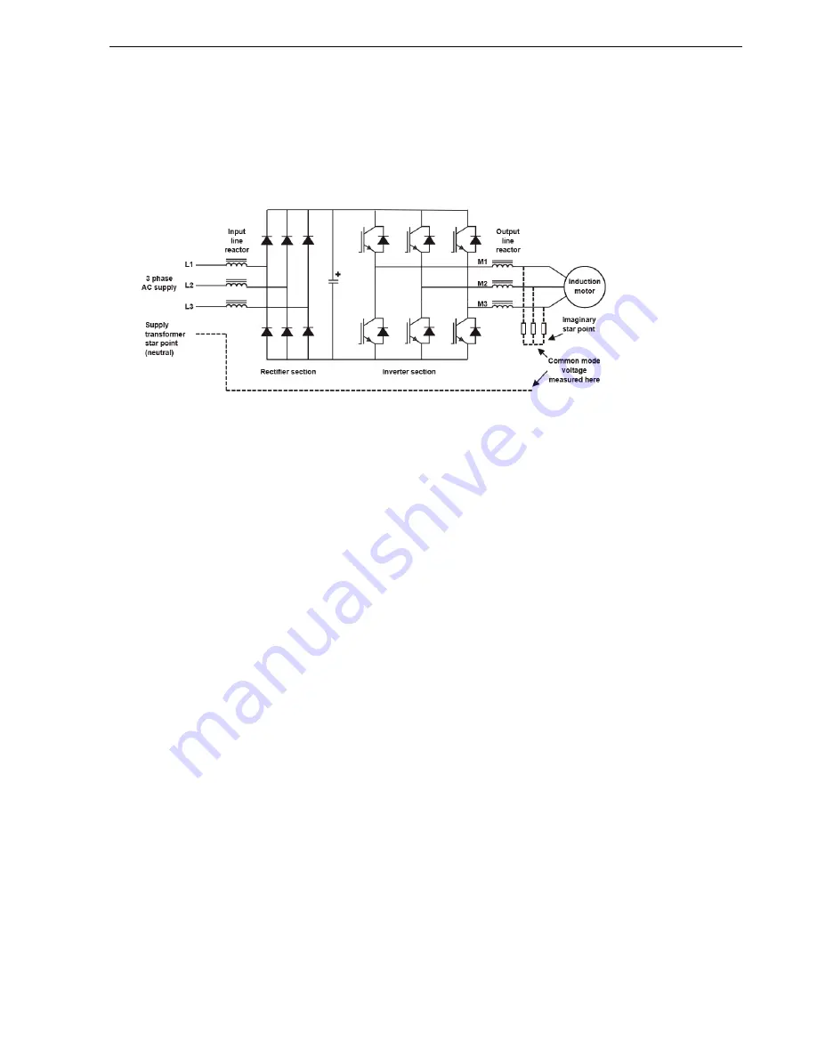
Location of common mode voltage
Common mode voltage and capacitive currents
A side effect of the PWM process is that there is also a voltage generated between an imaginary star point on
the 3 phases feeding the motor (M1/M2/M3) and the star point of the incoming AC supply.
This so called “common mode” voltage is of little consequence from a power point of view because there is no
“neutral” or “star point” connection on the output side of the inverter and therefore no path for current to flow
except through the small capacitance that exists between the motor circuit and ground. This capacitance will
be partly in the motor itself and partly in the associated cables. The current that is able to flow through this
capacitive path is quite small relative to the equipment current rating, however the nature, path and magnitude
needs to be considered in the design of a safe and reliable installation. There is a capacitive current path to any
conductor in the vicinity of the motor circuit and this is particularly so for any additional conductor that is within
or closely alongside the motor cable.
Nature of the capacitive leakage current
The capacitive leakage current takes the form of brief pulses. Each pulse is the result charging or discharging the
stray capacitances of the motor and cables with each change of the common mode voltage.
Capacitive leakage current path
The single line diagram below gives a general indication of the paths that the capacitively conducted currents
may typically take. Basic electrical circuit theory tells us that current flow will take the form of a loop. The key to
understanding the path capacitive leakage currents and possible interactions with other equipment or
instrumentation is to identify all of the elements of the loop.


