background image

5-10

IM 253710-01E

Explanation

WARNING

To ensure safety, if the current to be measured exceeds 7 A (RMS), use a cable
or conductor that allows current greater than the current to be measured to flow
through it, and always connect protective grounding prior to use of this
instrument.  For products shipped as of January 2004, the protective earth
terminal is located* on the rear panel.

*

If you need to confirm whether a protective earth terminal is installed, please contact the

dealer from whom you purchased the instrument.

Setting the voltage and current ranges

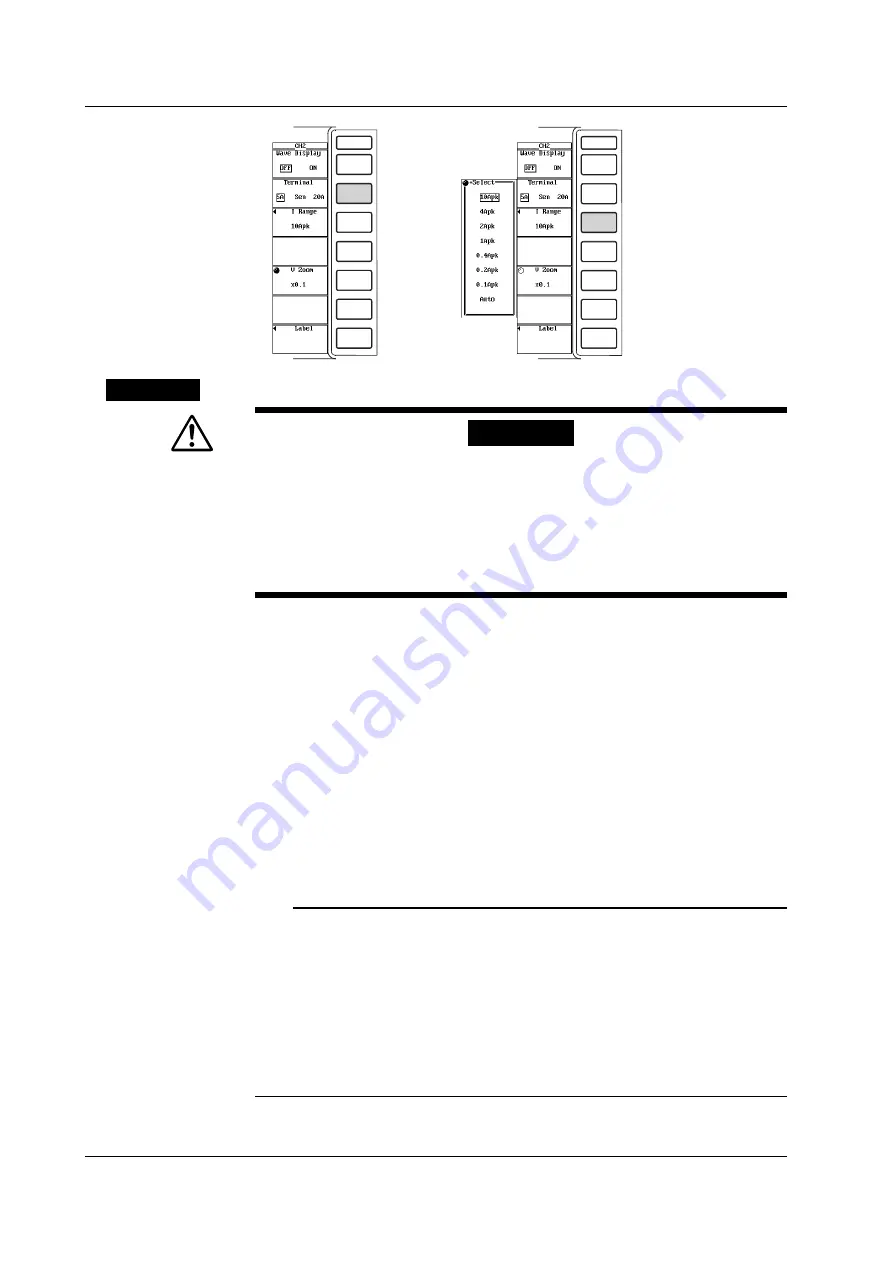
The voltage and current ranges can be set using the full screen menu or channel
setting menu.
There are two types of ranges, fixed and auto.

• Fixed range

• Voltage range

Select 2000Vpk, 1200Vpk, 600Vpk, 300Vpk, 200Vpk, 120Vpk, 60Vpk, or 30Vpk.

• Current range

• For the 5-A current input terminal

Select 10Apk, 4Apk, 2Apk, 1Apk, 0.4Apk, 0.2Apk, or 0.1Apk.

• For the 20-A current input terminal

Select 100Apk, 40Apk, 20Apk, 10Apk, 4Apk, 2Apk, or 1Apk.

Note

To set the range, refer to the peak value of the input signal.  For example, if a 100-Vrms

sinusoid is to be applied, the peak value is approximately 141 V.  Thus, set the range to

[200Vpk].

When measuring input signals that include pulse waveforms (such as PWM (Pulse Width

Modulation) inverter waveforms) through a line filter, turn the line filter OFF, and set the

range so that peak value of the input signal does not cause a peak over (as determined

when the Uover and Iover indicators in the upper left of the screen turn red).  In the case

of input signals that include pulse waveforms having frequencies which are higher than

line filter cut-off frequencies, the peak value of the input signal may not be correctly

detected depending on the specified range.

5.3  Setting the Measurement Range during Direct Input

Summary of Contents for PZ4000

Page 1: ...Power Analyzer IM 253710 01E 3rd Editionrr ...

Page 2: ...asing YOKOGAWA products YOKOGAWA provides registered users with a variety of information and services Please allow us to serve you best by completing the product registration form accessible from our homepage http tmi yokogawa com PIM 103 03E ...

Page 3: ...ins the communication functions of the GP IB Communication Interface and serial interfaces User s Manual Notes The contents of this manual are subject to change without prior notice as a result of continuing improvements to the instrument s performance and functions The figures given in this manual may differ from the actual screen Every effort has been made in the preparation of this manual to en...

Page 4: ...wer Cord Part No A1024WD Maximum rated voltage 250 V Maximum rated current 10 A H GB Standard Power Cord complies with the CCC Part No A1064WD Maximum rated voltage 250 V Maximum rated current 10 A Options M1 Extend memory to 1 Mword CH M3 Extend memory to 4 Mword CH B5 Built in printer C7 SCSI Only one of the options M1 or M3 can be selected Ex For UL CSA standard power cord 4 Mword CH memory ext...

Page 5: ...2 Two pieces in one set Two sets provided 5 Cover plate B9315DC 4 Attach cover plates on unused slots using screws see item 7 6 Current input B9315DJ 1 protective cover 7 Screw Y9305LB 20 M3 length 5 mm for fixing cover plates and current input protective covers in place 8 Clamp filtter A1179MN 1 For GP IB cable Ferrite core 9 User s Manual IM253710 01E 1 This manual Communication IM253710 11E 1 I...

Page 6: ...ent modules in order starting with the slot for element 1 Sensor input module 1 Model Code Suffix Code Specifications 253771 2 Motor module 2 channel input Allows signals to be input from revolution sensor or torque meter Module specification E1 Plug in unit 1 Install the sensor input module into the element 4 slot 2 This is applicable to products PZ4000 with firmware version 2 01 or later Ex For ...

Page 7: ...2 V or less length 2 m 4 Measurement lead 758917 1 Two leads in one set used with the separately sold adapter 758922 or 758929 length 0 75 m ratings 1000 Vrms 5 Alligator clip 758922 1 Two pieces in one set for the measurement lead adapter set 758917 Rated voltage 300 V 6 Alligator clip 758929 1 Two pieces in one set for the measurement lead adapter set 758917 Rated voltage 1000 V 7 Fork terminal ...

Page 8: ...d on this instrument Handle with care To avoid injury death of personnel or damage to the instrument the operator must refer to the explanation in the User s Manual or Service Manual Alternating current Both direct and alternating current ON power OFF power In position of a bistable push control Out position of a bistable push control Protective Earth Terminal To ensure safety if the current to be...

Page 9: ... the protective earth or the fuse might be defective Also make sure to check them before operation Fuse To prevent fire only use a fuse that has a rating voltage current and type that is specified by the instrument When replacing a fuse turn OFF the power switch and unplug the power cord Never short the fuse holder Do Not Operate in Explosive Atmosphere Do not operate the instrument in the presenc...

Page 10: ... EC marking requirement This marking indicates that you must not discard this electrical electronic product in domestic household waste Product Category With reference to the equipment types in the WEEE directive Annex 1 this product is classified as a Monitoring and Control instrumentation product Do not dispose in domestic household waste When disposing products in the EU contact your local Yoko...

Page 11: ...f the voltage current signals acquisition Chapter 8 Numerical Display Describes how to display measurement function data numerical data Chapter 9 Waveform Display Describes how to display the waveforms of the voltage and current signals Chapter 10 Numerical Computations Describes how to set numerical computations such as the delta computation user definitions and averaging Chapter 11 Waveform Anal...

Page 12: ...l Compensation NULL Function 1 17 1 4 Trigger 1 18 Trigger Source Trigger Slope Trigger Level Trigger Type 1 18 Trigger Mode 1 19 Trigger Position Trigger Delay 1 21 1 5 Numerical Display 1 22 Numerical display during the normal measurement mode 1 22 Numerical display during the harmonic measurement mode 1 23 Resetting the Numerical Display 1 25 1 6 Waveform Display 1 26 Vertical Amplitude Axis an...

Page 13: ...ment 3 11 Wiring to the voltage current input terminal of the power measurement module 3 8 Using an External Current Sensor to Wire the Circuit under Measurement 3 15 Wiring to the current sensor input connector of the power measurement module 3 9 Using an External PT or CT to Wire the Circuit under Measurement 3 19 Wiring to the voltage current input terminal of the power measurement module 3 10 ...

Page 14: ...ent Data 8 2 8 3 Changing the Displayed Items of the Normal Measurement Data 8 8 The following section applies when the measurement mode is set to harmonic measurement 8 4 Displaying Harmonic Measurement Data 8 11 8 5 Changing the Displayed Items of the Harmonic Measurement Data 8 19 Chapter 9 Waveform Display 9 1 Selecting the Channel to Display 9 1 9 2 Moving the Vertical Position 9 5 9 3 Splitt...

Page 15: ...ursor 11 10 Chapter 12 Saving and Loading the Data 12 1 Precautions on the Use of the Floppy Drive 12 1 12 2 Connecting SCSI Devices 12 2 12 3 Changing the SCSI ID Number 12 3 12 4 Formatting the Disk 12 5 12 5 Saving and Loading Setup Parameters 12 10 12 6 Saving and Loading Waveform Data 12 16 12 7 Saving Numerical Data 12 22 12 8 Changing the File Attribute Deleting Files 12 28 12 9 Copying Fil...

Page 16: ...xis 17 1 17 4 Measurement Function Measurement Item 17 2 17 5 Functions 17 6 Measurement Mode and Wiring Method Data Acquisition Frequency Measurement 17 6 Trigger Numerical Display Waveform Display 17 7 Vector Bar Graph Displays Simultaneous display Numerical computation WaveformAnalysis 17 8 Harmonic Measurement Save and Load data Output Screen Image Data 17 9 17 6 External Trigger I O Section 1...

Page 17: ...ut one type of signal PT Voltage Input one type of signal Screen image data Complies with EIA 574 Standard EIA 232 RS 232 Standard for 9 pin PC External trigger output External trigger input External clock input PZ4000 Waveform data Setup parameters Numerical data Waveform data Setup parameters Numerical data Screen image data Waveform data Setup parameters Numerical data Screen image data Wavefor...

Page 18: ...PF 20 kHz LPF 500 Hz Resistor Resistor 1 MΩ Zero Crossing Detector Zero Crossing Detector Applies only to 253752 Zero Crossing Data Zero Crossing Data Motor module Model 253771 OP AMP 12 bit A D Photo Isolator Speed data Torque data LPF 100 Hz LPF 500 Hz Resistor Resistor 1 MΩ Zero Crossing Detector Zero Crossing Detector Zero Crossing Data Zero Crossing Data Counter Pulse Analog Speed OP AMP 12 b...

Page 19: ...r The other way utilizes a current input terminal I which is used to directly input the current signal There are three systems on the 253752 two current input terminals and one current sensor For current sensor input the input voltage is normalized using the voltage divider and OP amp For the direct input the signal applied to the current input terminal is converted to voltage using a current divi...

Page 20: ...nal clock and updates the count value PZ4000 main unit Model 253710 The output from the A D converter and the zero crossing detector of the module is passed to the main unit of the 253751 via the photo isolator Up to eight channels of sampled data and zero crossing data are recorded into the acquisition memory ACQ memory along with the external trigger and external clock conditions according to th...

Page 21: ...n parallel Pc Corrected Power Measurement function of the average or sum of multiple measurement modules Σfunction The following 19 types of numerical data can be determined For details related to the determination of measurement function data see Appendix 2 UΣ voltage average UrmsΣ UmnΣ UdcΣ UacΣ IΣ current average IrmsΣ ImnΣ IdcΣ IacΣ PΣ sum of active powers SΣ sum of apparent powers QΣ sum of r...

Page 22: ...main unit can contain up to four elements which are numbered from one to four On power measurement modules one voltage and current pair can be input to each element The element number is appended to the symbols that were defined in the earlier section Measurement function on each power measurement module so that the correspondence can be seen For example Urms1 represents the true rms value of the ...

Page 23: ...Yes Yes Yes Yes Yes Yes No No No No No No No No No No No Yes Yes Yes Yes Yes Yes Yes Yes Yes Yes Yes U I P S Q λ φ φU φI Z Rs Xs Rp Xp Uhdf Ihdf Phdf Uthd Ithd Pthd Uthf Ithf Utif Itif hvf hcf fU fI Chars and numbers inside Measurement Function Measurement functions having parentheses have the following meanings depending on the characters or numbers that are inside the parentheses dc Indicates nu...

Page 24: ...1 Harmonic measurement function of the average or of the sum of the power measurement modules Σfunction The following six types of numerical data can be determined For details related to the determination of the measurement function see Appendix 2 dc Yes Yes Yes Yes Always 0 Yes 1 Yes Yes Yes Yes Yes Yes k Yes Yes Yes Yes Yes Yes All No Yes Yes Yes Yes Yes Yes UΣ IΣ PΣ SΣ QΣ λΣ Chars and numbers i...

Page 25: ...that were defined in the earlier section Harmonic measurement function on each power measurement module so that the correspondence can be seen For example U1 2 represents the 2nd order harmonic voltage of element 1 Wiring method The wiring method is the method by which the signals that are input to each element are combined Different selections are possible depending on the number of elements that...

Page 26: ...e input signal crosses the zero level the center value of the amplitude on a rising slope to the last point on the screen where the signal crosses the zero level on a rising slope When there is only one or there is no rising slope on the screen the measurement computation period is set to the entire width of the screen When using the zero crossing setting you can specify which input signal to use ...

Page 27: ...urement modules installed In some cases only one type of wiring method can be selected while in other cases two types of wiring methods can be selected The following five wiring methods are available 1P2W single phase two wire 1P3W single phase three wire 3P3W three phase three wire 3V3A three voltage three current 3P4W three phase four wire When determining the Σfunctions such as voltage current ...

Page 28: ...d the record length explained later For the relationship between the observation time sampling rate and record length see Appendix 1 Input module The input module is equipped with terminals for inputting voltage and current signals It is installed into the slot located on the rear side of the main unit model 253710 For the different types see Input module on page iv Element and Channel Element Whe...

Page 29: ...he Measurement Range during Direct Input Wiring Method Power Range 1P2W single phase two wire voltage range current range 1P3W single phase three wire voltage range current range 2 3P3W three phase three wire when the voltage and current ranges on the 3V3A three voltage three current corresponding elements are set to the same range 3P4W three phase four wire voltage range current range 3 when the ...

Page 30: ...put of C Ipk2 C Input Filter Line Filter and Zero Crossing Filter For procedures see section 5 6 There are two types of filters This instrument makes measurements by synchronizing to the input signal Therefore the frequency of the input signal must be measured accurately These filters are used for this purpose Line filter This filter is inserted into the measurement circuit It removes the noise fr...

Page 31: ...t be set uniformly as in the normal measurement mode In the harmonic measurement mode the time it takes to store the record length of sampled data in the acquisition memory is the time displayed on one screen Record length For procedures see section 6 2 During the normal measurement mode On this instrument the record length refers to the data capacity of the acquisition memory per channel It can b...

Page 32: ...d the numerical data and waveform are displayed based on the previous sampled data This function of dividing the record length can be used when you wish to analyze a waveform while viewing a waveform that is being continuously acquired When the memory is not divided Data acquisition aborted Display record length Data are displayed Data are not displayed Display record length One memory One memory ...

Page 33: ... zero level can be forcibly compensated NULL Function For procedures see section 4 5 The Udc and Idc numerical data of the simple average of the voltage and current in the normal measurement mode as well as Speed and Torque when using the motor module and the input signal from the sensor is a DC voltage that have been measured when the NULL function is turned ON are set as NULL values The null val...

Page 34: ...procedures see section 7 3 Trigger level refers to the level that is used to judge the passing level of the trigger slope or the condition of the trigger source Trigger Type For procedures see section 7 3 7 4 There are two types of triggers edge trigger and window trigger Edge trigger A trigger occurs when the trigger source rises above or falls below a preset trigger level The trigger source can ...

Page 35: ...en the trigger position described in the next section and the trigger point are matched and the trigger position is located on the left end of the screen In this case when a trigger occurs after the data acquisition is started an amount of data equal to the display record length is displayed starting from the trigger point Note The following figure indicates the schematic of acquiring sampled data...

Page 36: ...e 1 2 of the amplitude Trigger level Amplitude Normal mode The waveform display is updated only when the trigger occurs If a trigger does not occur the display is not updated HF auto mode The output of the zero crossing detector of the trigger source is used to detect the trigger condition When the zero crossing filter is set the trigger becomes less susceptive to harmonic noise and unexpected tri...

Page 37: ...that existed before the trigger point The section before the trigger position is called the pre trigger section and the section after the trigger position is called the post trigger section If the observation time described earlier is changed the display range changes around the trigger position Acquisition memory Displayed record length Trigger position Trigger point Displayed on the screen Trigg...

Page 38: ...al display during the normal measurement mode For procedures see section 8 2 8 3 Selecting the number of displayed items You can select the number of displayed items in the range from eight to all When the numerical data and waveform are displayed at the same time only half of the selected number of items is displayed All items cannot fit on one screen Thus a scroll function is provided so that al...

Page 39: ...ocedures see section 8 4 8 5 Selecting the number of displayed items You can select either eight or 16 for the number of displayed items When the numerical data and waveform are displayed at the same time only half of the selected number of items are displayed All items cannot fit on one screen Thus a scroll function is provided so that all data can be viewed Example in which eight items are displ...

Page 40: ...ayed at the same time approximately half of the data is displayed Single list The data of one measurement function are displayed by separating the even and odd harmonics in each column You can select the following measurement functions U I P S Q λ φ φU φI Z Rs Xs Rp Xp and Torque This is applicable to products PZ4000 with firmware version 2 01 or later when the motor module is installed in the ele...

Page 41: ...rmonic order Data related to the all harmonic signals Σ List Displays the measurement function data such as U I P S Q λ and φ of each element and wiring methods A and B for the selected harmonic orders Measurement function Element and wiring method Page scroll of the list The data of all harmonics cannot fit on one screen Thus a scroll function is provided so that all data can be viewed Resetting ...

Page 42: ... a more accurate waveform display The instrument uses a 12 bit A D converter which results in the quantization of the sampled data using 4096 discrete levels However the waveform is displayed using 512 levels per grid On the other hand when using cursors explained later to measure the data from the waveform the data are converted to a resolution of up to 16 bits Horizontal time axis The instrument...

Page 43: ...cenarios occur When the display record length is larger than the number of displayed points For each time segment the instrument performs P P compression P P compression refers to the determination of the maximum and minimum values for each segment One raster will display these two points When the display record length is less than the number of displayed points The instrument interpolates the dis...

Page 44: ...ndow The screen can be divided into up to four windows This function is useful when there are many waveforms on the screen You can select the method of assignment from the following list of choices Auto The channels that are turned ON are assigned in order according to the channel number to the divided windows Fixed The channels are assigned in order according to the channel number to the divided ...

Page 45: ...o lower the P P compression rate so that each sampled data point in the acquisition memory can be observed The maximum zoom factor that can be selected depends on the display record length and observation time For example the maximum zoom factor is 10 000 times when the observation time is 20 s and the display record length is 100 k words It is 100 000 times when the observation time is 20 s and t...

Page 46: ...n waveform screen The center of the zoom box indicates the center of the zoomed waveform Main waveform display frame Z1 waveform display frame Z2 waveform display frame Z2 zoom box Z1 zoom box Split screen of the zoomed waveform As described in the earlier section Split Screen of the Waveform the screen can be evenly divided and the waveform of each channel can be automatically assigned to the div...

Page 47: ...when the wiring method is 3P4W three phase four wire U1 1 U2 1 and U3 1 are common mode voltages I1 1 I2 1 and I3 1 are line currents Vector display when the wiring method is 3V3A three voltage three current U1 1 U2 1 and U3 1 are line voltages I1 1 I2 1 and I3 1 are line currents By moving the vectors U1 1 U2 1 and U3 1 without changing their orientations so that the starting points of vectors ar...

Page 48: ...in the element number 4 slot Bar Graph Display of Harmonic Data The measured values of marker and for bar graph 1 The measured values of marker and for bar graph 2 Marker Marker Harmonic order indicating the marker position Applicable to products with firmware version 2 01 or later Marker and indicate that they are at the 1st order and 13th order positions respectively X Y Waveform Display For pro...

Page 49: ...he scale value The upper and lower limits of the vertical axis and the values at the left and right ends of the horizontal axis time axis of each channel can be turned ON or OFF Displaying the Waveform Labels The waveform labels of each channel can be turned ON or OFF Right end time axis Left end time axis Lower limits Upper limits Waveform label Applicable to products with firmware version 2 01 o...

Page 50: ...rement Modes and Measurement Computation Periods User defined Functions For procedures see section 10 3 An equation can be created defined by combining the measurement function symbols and operators The numerical data corresponding to the equation can then be determined The combination of a measurement function and element number Urms1 for example constitutes an operand Four equations F1 to F4 can...

Page 51: ...e at the nth time that has been exponentially averaged The displayed value D1 on the first time is M1 Dn 1 Display value at the n 1 time that has been exponentially averaged Mn Measured data at the nth time K Attenuation constant Select 2 4 8 16 32 or 64 Phase Difference For procedures see section 10 6 The display format of the phase difference of the voltage and current can be selected With the r...

Page 52: ...al transformer that is measured need to be compensated The compensating equation and the coefficient can be selected IEC76 1 1976 IEEE C57 12 90 1993 IEC76 1 1993 P P1 P2 Urms Umn 2 Pc P Umn Urms Umn 1 Pc Pc Corrected Power P Active power Urms True rms voltage Umn Voltage rectified mean value calibrated to the rms value P1 P2 Coefficient as defined in the applicable standard Re computing the numer...

Page 53: ...clock or when the measurement mode is harmonic t 1 s TREND The instantaneous value sampled data of the measured signal can be computed in the same fashion as determining each measurement function for each cycle of the synchronized signal and the TREND waveforms of the following measurement functions can be displayed Measurement Function that Applicable Function Channel Symbol Placed Can Be Compute...

Page 54: ...sing a specified attenuation constant and the waveform can be displayed The items are averaged according to the following equation Example of an AVG function AVG C1 C2 Displays the AVG waveform of the active power of element 1 xn dn xn 1 k xn 1 xn Displayed value at the nth time The displayed value of x1 on the first time is d1 xn 1 Display value at the n 1 time that has been exponentially average...

Page 55: ... is one of the measurement functions of the motor module PM Displays the waveform changes over time of Pm motor output mechanical power Pm is one of the measurement functions of the motor module Display Scaling of a Computed Waveform For procedures see section 11 2 In general when displaying a computed waveform auto scaling can be used With auto scaling the upper and lower limits of the screen are...

Page 56: ...ing equation Voltage power spectrum Current power spectrum Power spectrum of the active power Ur Ir Real Part Uj Ij Imaginaly Part Ur 2 Uj 2 2 UrIr UjIj Take the complex function of the voltage after taking the FFT to be U Ur jUj and the complex function of the current to be I Ir jIj Ir 2 Ij 2 2 The difference between a harmonic measurement and a FFT on this instrument In the harmonic measurement ...

Page 57: ...ayed on the specified waveform These are markers The vertical value and the horizontal value from the left edge of the screen for each marker as well as the differences between the vertical values and the horizontal values of the markers can be measured H cursors horizontal cursors Two dotted horizontal lines are displayed These are H cursors The vertical value of each H cursor and the difference ...

Page 58: ...arious data can be saved or loaded from an external SCSI device in the same manner described above for the floppy disk This is useful when handling large amounts of data Zip disk hard disk drive MO disk PD disk etc PC PZ4000 SCSI device Initialization For procedures see section 4 2 The various setup parameters configured using operation keys and soft keys can be initialized to their factory defaul...

Page 59: ...orm data and setup parameters to the specified medium Output or save the screen image data to the specified destination Self test Function For procedures see section 15 3 A self test can be performed to check whether or not the instrument is operating properly Components such as the memory the operation keys the floppy disk drive and the built in printer option can be tested Confirming the System ...

Page 60: ...r occurs Section 14 1 External printer connector Centronics printers are connected here Section 13 3 GP IB and Serial RS 232 connectors For communication functions see the Communication Interface User s Manual IM253710 11E Power connector Section 3 6 Voltage input terminal Wire the voltage measurement cable Section 3 7 to 3 10 Current input terminal Wire current measurement cables Sections 3 7 3 9...

Page 61: ...2 2 IM 253710 01E Top View Built in printer option Sections 13 1 13 2 Vent holes Section 3 2 Rear panel Front panel 2 1 Front Panel Rear Panel and Top View ...

Page 62: ...ion key or soft key that is pressed after pressing this key Section 4 6 Shuttle ring Set Measurement Mode Acquisition Conditions of Measured Data and Trigger CONFIGURATION ELEMENTS VOLTAGE CURRENT FILTER 1 FILTER FILTER FILTER 2 3 4 RESET SELECT CH 8 CH 6 CH 4 CH 2 CH 7 CH 5 CH 3 CH 1 OBSERVATION TIME TRIG D ACQ REMOTE MENU SHIFT NULL CAL COPY LOCAL HELP MISC FILE ZOOM CURSOR MATH DISPLAY SETUP IN...

Page 63: ... 9 2 9 7 9 8 ZOOM key Vertically zoom on the waveforms Section 9 8 Set Numerical Computation and Waveform Analysis CONFIGURATION ELEMENTS VOLTAGE CURRENT FILTER 1 FILTER FILTER FILTER 2 3 4 RESET SELECT CH 8 CH 6 CH 4 CH 2 CH 7 CH 5 CH 3 CH 1 OBSERVATION TIME TRIG D ACQ REMOTE MENU SHIFT NULL CAL COPY LOCAL HELP MISC FILE ZOOM CURSOR MATH DISPLAY SETUP INPUT MEASURE TRIGGER ABORT E S C SINGLE STAR...

Page 64: ...guage set the brightness of the LCD monitor set displayed colors action on trigger perform self tests confirm system conditions Sections 12 3 14 2 14 3 14 4 16 3 16 4 FILE key Format disks save and load setup parameters and waveform data save numerical data change file attributes delete files copy files change the name of director file and create directories Sections 12 4 to 12 10 SHIFT COPY MENU ...

Page 65: ...d current respectively The input condition of each element Element 1 2 3 and 4 is indicated in order from the left However if the motor module is installed in the element number 4 slot and the revolution sensor signal is a pulse signal input the fourth indicator from the left on the top row remains green The observation time and sampling rate for data that are displayed on the screen When the obse...

Page 66: ...7 IM 253710 01E Names and Uses of Parts 2 42 items display Measurement function Data 78 items display Measurement function Data All display Measurement function Element and wiring method Data 2 3 Screens ...

Page 67: ... approx 125 level of the specified measurement range The first and second lines correspond to voltage and current respectively The input condition of each element Element 1 2 3 and 4 is indicated in order from the left However if the motor module is installed in the element number 4 slot and the revolution sensor signal is a pulse signal input the fourth indicator from the left on the top row rema...

Page 68: ...rmonic distortion factor Harmonic order Data related to all harmonics Measurement function Dual list Data related to all harmonics Numerical data of each harmonic Harmonic distortion factor Harmonic order Measurement function Σ list Measurement function Element and wiring method 2 3 Screens ...

Page 69: ...en For the normal measurement mode only When the observation time is changed while the data acquisition operation is stopped the new observation time and sampling rate are displayed here For the normal measurement mode only Menu Specified date and time Record length Left end time axis Lower limits Upper limits Waveform label Applicable to products with firmware version 2 01 or later Right end time...

Page 70: ...imes For a 3P4W three phase four wire wiring system For a 3P3W three phase three wire wiring system The value indicating the size of the peripheral circle range The size of the vector representing the voltage and current is expanded 4 times and 2 times respectively The voltage range and current range values are reduced to 1 4 and 1 2 the original values respectively For a 3V3A three voltage three ...

Page 71: ...cating the marker position Applicable to products with firmware version 2 01 or later Marker and indicate that they are at the 1st order and 13th order positions respectively Cursor measurement display For Markers For H Cursors For H V Cursors For V Cursors Cursor 2 Cursor 2 Cursor 1 Cursor 2 Cursor 1 Cursor 1 Cursor 4 Cursor 3 Cursor 1 Cursor 2 Measured values Measured values Measured values Meas...

Page 72: ...2 13 IM 253710 01E Names and Uses of Parts 2 Simultaneous Displays of Numerical Data and Waveforms Simultaneous Displays of Numerical Data and Bar Graphs 2 3 Screens ...

Page 73: ...Current sensor input connector Connect the external sensor cable from the external current sensor Section 3 8 Model 253752 Voltage input terminal Wire the voltage measurement cable Section 3 7 to 3 10 Current input terminal Wire current measurement cables Two terminals are available for maximum ratings of 5 Arms and 20 Arms Sections 3 7 3 9 Current sensor input connector Connect the external senso...

Page 74: ... module Model 253771 motor module Torque meter signal Input connector CH8 Connect a cable from an external torque meter Section 15 1 Revolution sensor signal Input connector CH7 Connect a cable from an external revolution sensor Section 15 1 2 4 Input Modules ...

Page 75: ...t your dealer for replacement Refer to page ii for the part number when placing an order General Handling Precautions Never place anything on top of the instrument Never place another instrument or any objects containing water on top of the instrument This may cause problems Keep electrically charged objects away from the instrument Keep electrically charged objects away from the input terminals T...

Page 76: ...ation is high In an unstable place Note For the most accurate measurements use the instrument in the following environment Ambient temperature 23 3 C Ambient humidity 50 10 RH no condensation When using the instrument in a place where the ambient temperature is 5 to 20 C or 26 to 40 C add the temperature coefficient to the accuracy of the module as specified in chapter 17 When installing the instr...

Page 77: ...w For details regarding the attachment procedures see the instructions that are included with the rack mount kit 1 Remove the handle on each side of the instrument 2 Remove the four feet on the bottom of the instrument 3 Remove the plastic revet and the four seals covering the rack mount attachment holes on both sides of the instrument near the front 4 Places seals over the feet and handle attachm...

Page 78: ...rrent 5 A current sensor 500 mV 253752 Power measurement module Voltage 1000 V current 5 A 20 A current sensor 500 mV 253771 Sensor input module Motor module 2 channel input Input signals from revolution sensor or torque meter Precautions when Installing or Removing Input Modules Install the power measurement modules in numerical order starting from the slot of element 1 If you skip elements that ...

Page 79: ...rect model name for the input module is displayed at the element number in which the input module was installed If it is not correct remove the module according to the Removal Procedure described below and re install the module according to the above steps 1 to 5 For details regarding the information screen see section 16 4 Checking the System Condition 7 After connecting the measurement cable acc...

Page 80: ...terminals Note that only one system one set of current input terminals can be used on a module at any given time Remove all other cables connected to the current input terminals or current sensor input connector When the voltage of the circuit under measurement is being applied to the current input terminals do not touch the other current input terminals or current sensor terminals Since these ter...

Page 81: ... 20 A terminal The peak value is 150 A or the RMS value is 40 A which ever is less Continuous max Same as the 5 A terminal The peak value is 10 A or the Instantaneous max RMS value is 7 A which ever is shown above less 20 A terminal The peak value is 100 A or the RMS value is 30 A which ever is less CAUTION Use measurement cables that have adequate margins of withstand voltage and current capacity...

Page 82: ...ment is 0 01 or less If the input is 100 V and 10 A iV 0 1 mA 100 V 1 MΩ then the effect of iV on the measurement accuracy is 0 001 0 1 mA 10 A SOURCE LOAD This instrument U I iV iL SOURCE LOAD Input terminal ELEMENT I U As a reference the relationship of the voltages and currents that produce effects of 0 1 0 01 and 0 001 are shown in the figure below 1000 800 600 400 200 0 Measured current A Mea...

Page 83: ...be considered load current iL and the current that flows through the stray capacitance iCs iL flows through the current measurement circuit then through the load and returns to the power source shown with a dotted line iCs flows through the current measurement source through the stray capacitance and then through the earth ground of the outer case and returns to the power source shown with a dot d...

Page 84: ...e an extension cord that does not have protective earth otherwise the protection function will be compromised Connecting Procedure 1 Check that the power switch is OFF 2 Connect the plug of the accessory power cord to the power connector on the rear panel of the instrument 3 Plug the other end of the power cord into a power outlet that satisfies the conditions below The AC outlet must be a three p...

Page 85: ...ypes of terminals 5 A and 20 A terminals but only one system of current input one set of current input terminals can be used on each input module at one time To prevent electric shock and damage to the instrument do not wire measurement cables to multiple current input terminals simultaneously The screws used on the terminal binding post are M6 screws Either wind the wire around the screw or pass ...

Page 86: ...em 3P4W three phase four wire system Note Check that the power measurement modules are installed in order starting from the element number 1 slot If you leave the slots that have smaller element numbers empty measurements will not be made properly For example do not install a power measurement module into the element number 2 slot and leave the element number 1 slot empty Do not install power meas...

Page 87: ...system 1P3W If power measurement modules are installed in all four slots then two single phase three wire systems can be set up elements 1 and 2 and elements 3 and 4 The combination of elements that can be wired to the input terminals in the figure are as follows The rest of the elements can be wired to single phase two wire systems Input Terminal 1 Input Terminal 2 Element 1 Element 2 Element 2 E...

Page 88: ...e wired to the input terminals in the figure are as follows The rest of the elements can be wired to single phase two wire systems Input Terminal 1 Input Terminal 2 Input Terminal 3 Element 1 Element 2 Element 3 Element 2 Element 3 Element 4 SOURCE LOAD I I R S T U U U I SOURCE Input Terminal 1 I U LOAD Input Terminal 2 I U R S T I1 I2 I3 U3 U1 U2 Input Terminal 3 I U Wiring Example of a three pha...

Page 89: ...3751 When the maximum current exceeds 7 Arms or 10 Apeak Power measurement module 253752 5 A terminal When the maximum current exceeds 7 Arms or 10 Apeak 20 A terminal When the maximum current exceeds 30 Arms or 100 Apeak A shunt type or clamp type current sensor can be used for an external current sensor Connecting to the current sensor input connector Connect an external sensor cable with the BN...

Page 90: ...current is reversed and proper measurements cannot be made Be especially careful when using a clamp type current sensor because it is easy to reverse the connection To minimize error when using a shunt type sensor note the following points when connecting the external sensor cable Connect the shielded wire of the external sensor cable to the L side of the shunt output terminal OUT Minimize the are...

Page 91: ...t sensors When connecting a clamp type current sensor replace the shunt type current sensor with the clamp type For the combinations of the elements and the input terminals in the figures below see Wiring Examples in section 3 7 Directly Wiring the Circuit under Measurement Wiring Example of a single phase two wire system 1P2W using a shunt type current sensor SOURCE LOAD Earth side Shunt type cur...

Page 92: ... L OUT H I OUT L OUT H R S T I OUT L OUT H Current sensor input connector Input terminal 3 U Current sensor input connector Input terminal 2 U Current sensor input connector Input terminal 1 U Wiring Example of a three phase four wire system 3P4W using a shunt type current sensor SOURCE LOAD I OUT L OUT H I OUT L OUT H R S T N I OUT L OUT H Current sensor input connector Input terminal 3 U Current...

Page 93: ...exceeds 30 Arms or 100 Apeak Connecting to the Input Terminal Voltage input terminal Insert the safety terminal the conductive parts are not exposed into the voltage input terminal Current input terminal The power measurement module 253751 has 5 A terminals Power measurement module 253752 has two types of terminals 5 A and 20 A terminals but only one system of current input one set of current inpu...

Page 94: ...T Note that the frequency and phase characteristics of the PT or CT affect the measured data To measure the apparent power and power factor more accurately when measuring the power of an unbalanced three phase circuit it is recommended that a three voltage three current 3V3A system be used to make the measurement In 3P3W and 3V3A systems the wiring system may be different between the PZ4000 and an...

Page 95: ... V v l LOAD R S T Input terminal 1 I U Input terminal 2 I U Input terminal 3 I U Wiring Example of a three phase four wire system 3P4W using PT and CT Input terminal 1 I U L CT PT V v l L CT PT V v l SOURCE L CT PT V v l LOAD R S T N Input terminal 3 I U Input terminal 2 I U Note For details about the relationship between the wiring system and how measured and computed values are determined see ap...

Page 96: ...ensor input connector and between the current input terminal and current sensor input connector is 600 V Do not apply a voltage exceeding 600 V The rated voltage between the U voltage input terminal and the terminal of voltage input terminal is 1000 V Do not apply a voltage exceeding 1000 V When the voltage across the voltage input terminals exceeds 600 V do not directly input the current to the c...

Page 97: ...er in Turning ON OFF the Power When using the model with the SCSI option and you wish to save or load data using an external SCSI device turn ON the SCSI device first then turn ON this instrument When turning OFF the instrument and SCSI device reverse the order Power Up Operation When the power switch is turned ON the self test starts automatically When the self test completes successfully the dis...

Page 98: ...gets disconnected from the outlet The next time the power switch is turned ON the instrument powers up using the stored setup parameters Note A lithium battery is used to retain the setup parameters When the lithium battery voltage falls below a certain level a message is displayed on the screen see section 16 2 when the power switch is turned ON When this message appears frequently the battery mu...

Page 99: ... 2 Press the Date Time soft key to display the date time setting dialog box Turning ON OFF the date time display 3 Turn the jog shuttle to select Display 4 Press the SELECT key to select ON or OFF Setting the date or time 5 Turn the jog shuttle to select Date or Time 6 Press the SELECT key to display the keyboard 7 Use the keyboard to set the date or time For keyboard operations see section 4 1 En...

Page 100: ...in the form HH MM SS hour minute second The hour is set using a 24 hour clock Confirming the new settings When the date time is turned ON OFF it is immediately reflected on the screen However if you are changing the date and time you must confirm the new settings If you do not abort the operation the new settings will not take effect Note The date and time information is backed up with the lithium...

Page 101: ...y is pressed Entering Strings The date time file name and comment can be entered using the keyboard that is displayed on the screen The jog shuttle SELECT key and arrow keys are used to operate the keyboard to enter the character strings The keyboard that is displayed when creating equations for user defined functions and waveform computations contain special keys See the Note on the next page Ope...

Page 102: ...ions for user defined functions and waveform computations is as follows Long function names can be selected by pressing one key Long equations can be temporarily held in the internal memory so that it can be used in other equations The procedure to store equations in the internal memory is as follows 1 After setting the equation select ENTER on the keyboard 2 When the SELECT key is pressed the equ...

Page 103: ... 12 5 before initialization 1 Press the SETUP key 2 Press the Initialize soft key Select OK on the dialog box be appeared to execute the initialization Explanation The values set with the keys can be reset to their factory default values This function is useful when you wish to clear the previous settings or restart a configuration from the beginning For details on the default settings see Appendi...

Page 104: ...on Data acquisition is in progress when the indicator on the key is lit Operation when the SINGLE START key is pressed Pressing the SINGLE START key starts the data acquisition operation the indicator on the START STOP key lights After the data are acquired once according to the trigger settings the acquisition operation stops automatically the indicator on the START STOP key turns off Operation w...

Page 105: ...omputed or displayed and the waveform cannot be displayed This condition can be avoided by dividing the record length For information on dividing the record length see section 6 2 Selecting the Record Length for Acquiring Data Conditions in which the START STOP key and SINGLE START key are void During Remote mode REMOTE indicator is lit While printing While accessing the medium Note If the acquisi...

Page 106: ...and then sets the zero level to that value Zero level compensation must be performed to meet the specifications of this instrument see chapter 17 Pressing the CAL key performs the zero level compensation Zero level compensation is performed the first time a measurement is made after changing the measurement mode measurement range input terminal and input filter Note For making accurate measurement...

Page 107: ...average of the voltage and current during the normal measurement mode U dc and I dc during the harmonic measurement mode as well as Speed and Torque when using the motor module and the input signal from the sensor is a DC voltage that were measured the previous time If the previously measured Udc and Idc as well as Speed and Torque values do not exist such as when the NULL function is turned ON wi...

Page 108: ...ocedures Displaying the help window 1 Press the HELP key to open the help window 2 Press the operation key or soft key corresponding to the setup parameters you wish to check The setup data related to the pressed key are displayed Closing the help window 3 Press the HELP key when the help window is being displayed The help window disappears Explanation When the HELP key is pressed a help window is...

Page 109: ...RIGGER ABORT E S C SINGLE START START STOP Procedure 1 Press the SETUP key to display the Setup menu 2 Press the Mode soft key to display the measurement mode selection menu 3 Press the Normal or Harmonics soft key to select the measurement mode Explanation There are two measurement modes normal measurement and harmonic measurement The handling of the sampled data and the types of measurement func...

Page 110: ...hod 4 Press the SELECT key to confirm the wiring method Explanation The wiring method is the method by which the signals that are input to each element are combined The numerical data of Σfunctions are determined according to the wiring method The selectable wiring methods vary depending on which element slots have power measurement modules installed The wiring method can be selected from the tabl...

Page 111: ...ΣB Displays the numerical data of element 2 Element 3 is also handled as 1P2W It does not affect ΣA and ΣB 1P2W 1P3W ΣA Displays the numerical data of element 1 ΣB Displays the numerical data when elements 2 and 3 are combined into a 1P3W system 1P2W 3P3W ΣA Displays the numerical data of element 1 ΣB Displays the numerical data when elements 2 and 3 are combined into a 3P3W system 1P3W 1P2W ΣA Di...

Page 112: ...he numerical data of element 3 Element 4 is handled as 1P2W It does not affect ΣA and ΣB 1P3W 1P3W ΣA Displays the numerical data when elements 1 and 2 are combined into a 1P3W system ΣB Displays the numerical data when elements 3 and 4 are combined into a 1P3W system 1P3W 3P3W ΣA Displays the numerical data when elements 1 and 2 are combined into a 1P3W system ΣB Displays the numerical data when ...

Page 113: ...odule When the sensor input module is installed into the element number 4 slot only up to three power measurement modules can be installed In this case you cannot select a wiring method that uses four power measurement modules Select the wiring method that matches the actual wiring of the circuit The method in determining the Σfunctions varies depending on the wiring method If the wiring method se...

Page 114: ...n Menu for Each Element Sets the range of the power measurement module for each element 1 Press the INPUT key to display the Input setting menu On products PZ4000 with firmware version before 2 01 only the Power Module soft key appears 2 Press the Power Module Each soft key to display the power module setting dialog box The menu does not appear for elements without modules If the sensor input modu...

Page 115: ...wer measurement module 253751 Selecting the voltage range 5 Turn the jog shuttle to select the I Range of the element you wish to set 6 Press the SELECT key to display the current range selection box 7 Turn the jog shuttle to select the current range from 10Apk to 0 1Apk and Auto or 100Apk to 1Apk and Auto when the current input terminal is 5A or 20A respectively 8 Press the SELECT key to confirm ...

Page 116: ...lect the Terminal of element 1 4 Press the SELECT key to select 5A or 20A The Terminal of all other modules that are displayed are set to the same value 5A or 20A 20A cannot be selected on the power measurement module 253751 Even when 20A is selected for the power measurement module 253752 of element 1 other modules that are not 253752s are not set to 20A When element 1 is a power measurement modu...

Page 117: ...tting the current range 1 Select the desired channel key from the CH2 CH4 CH6 and CH8 keys The channel setting menu appears If the CH8 key is pressed when the motor module is installed in the element number 4 slot the menu for the torque signal input appears For the procedure see chapter 15 Selecting the current input terminal 2 Press the Terminal soft key to select 5A or 20A 20A cannot be selecte...

Page 118: ...rrent range For the 5 A current input terminal Select 10Apk 4Apk 2Apk 1Apk 0 4Apk 0 2Apk or 0 1Apk For the 20 A current input terminal Select 100Apk 40Apk 20Apk 10Apk 4Apk 2Apk or 1Apk Note To set the range refer to the peak value of the input signal For example if a 100 Vrms sinusoid is to be applied the peak value is approximately 141 V Thus set the range to 200Vpk When measuring input signals t...

Page 119: ...nstant In this case use a fixed range setting When measuring input signals that include pulse waveforms through a line filter the range may not be set correctly by the auto range function and measurements may be inaccurate When measuring such input signals as PWM inverter waveforms It is recommended that you perform the measurements using the fixed range determined by the PWM crest value Power ran...

Page 120: ...000 W 400 00 W 400 000 W 800 00 W 800 000 W 2 0000 kW 2 00000 kW 4 0000 kW 4 00000 kW 8 0000 kW 8 00000 kW 20 000 kW 20 0000 kW 40 000 kW 40 0000 kW 80 000 kW 80 0000 kW 200 00 kW 200 000 kW Wiring Method 1P2W Current Range Apk Voltage Range Vpk 30 60 120 200 300 600 1200 2000 Displayed digits 5 digits 6 digits 5 digits 6 digits 5 digits 6 digits 5 digits 6 digits 5 digits 6 digits 5 digits 6 digi...

Page 121: ...W 600 00 W 600 000 W 1200 0 W 1200 00 W 2 4000 kW 2 40000 kW 6 0000 kW 6 00000 kW 12 000 kW 12 0000 kW 24 000 kW 24 0000 kW 60 000 kW 60 0000 kW 90 000 W 90 0000 W 180 00 W 180 000 W 360 00 W 360 000 W 900 00 W 900 000 W 1 8000 kW 1 80000 kW 3 6000 kW 3 60000 kW 9 0000 kW 9 00000 kW 18 000 kW 18 0000 kW 36 000 kW 36 0000 kW 90 000 kW 90 0000 kW 180 00 W 180 000 W 360 00 W 360 000 W 720 00 W 720 00...

Page 122: ...ment 1 Press the INPUT key to display the Input setting menu On products PZ4000 with firmware version before 2 01 only the Power Module soft key appears 2 Press the Power Module Each soft key to display the power module setting dialog box The menu does not appear for elements without modules If the sensor input module is installed in the element number 4 slot the menu for element 4 does not appear...

Page 123: ...et 10 Press the SELECT key to display the current sensor transformation ratio setting box 11 Turn the jog shuttle to set the transformation ratio For the procedures related to entering values using the jog shuttle see section 4 1 Entering Values and Strings 12 Press the SELECT key or the ESC key to close the setting box 5 4 Setting the Measurement Range when Using an External Current Sensor ...

Page 124: ...tle to select the I Range of element 1 6 Press the SELECT key to display the current sensor range selection box 7 Turn the jog shuttle to select the range from 1000mVpk to 100mVpk and Auto 8 Press the SELECT key to confirm the new current sensor range The I Range of all other modules that are set to the same current input terminal Terminal as element 1 are set to the same current range Setting the...

Page 125: ...t the menu for the torque signal input appears For the procedure see chapter 15 Selecting the current sensor input connector 2 Press the Terminal soft key to select Sen Selecting the current sensor range 3 Press the Sensor Range soft key to display the current sensor range selection box 4 Turn the jog shuttle to select the range from 1000mVpk to 100mVpk and Auto 5 Press the SELECT key to confirm t...

Page 126: ...e current sensor range and current sensor transformation ratio must be set Selecting the current sensor range There are two types of ranges fixed and auto Fixed range Select 1000mVpk 400mVpk 200mVpk or 100mVpk Auto range Select Auto at the range setting to enable auto range The range switches automatically depending on the amplitude of the input signal The conditions for which the range changes an...

Page 127: ... 10 mV A 100 Apk 1000 mVpk Therefore set 1000 mVpk for the current sensor range and 10 mV A for the current sensor transformation ratio Note When attempting to directly read the current of the circuit under measurement by multiplying the output of the external current sensor by the transformation ratio turn OFF the external PT CT scaling function see section 5 5 If it is turned ON the value will b...

Page 128: ...o display the Input setting menu On products PZ4000 with firmware version before 2 01 only the Power Module soft key appears 2 Press the Power Module Each soft key to display the power module setting dialog box The menu does not appear for elements without modules If the sensor input module is installed in the element number 4 slot the menu for element 4 does not appear Turn ON OFF the scaling fun...

Page 129: ...alues and Strings 6 Press the SELECT key or the ESC key to close the setting box Setting the power coefficient 3 Turn the jog shuttle to select the Scaling Factor of the element you wish to set 4 Press the SELECT key to display the power coefficient setting box 5 Turn the jog shuttle to set the power coefficient For the procedures related to entering values using the jog shuttle see section 4 1 En...

Page 130: ...ar Turn ON OFF the scaling function 3 Turn the jog shuttle to select the Scaling of element 1 4 Press the SELECT key to select ON or OFF The Scaling of all other modules that are displayed are set to the same value ON or OFF Setting the PT ratio 3 Turn the jog shuttle to select the PT Ratio of element 1 4 Press the SELECT key to display the PT ratio setting box 5 Turn the jog shuttle to set the PT...

Page 131: ...Ratio of all other modules that are displayed are set to the same CT ratio Setting the power coefficient 3 Turn the jog shuttle to select the Scaling Factor of element 1 4 Press the SELECT key to display the power coefficient setting box 5 Turn the jog shuttle to set the power coefficient For the procedures related to entering values using the jog shuttle see section 4 1 Entering Values and String...

Page 132: ...d CT are read directly as numerical data in this case Setting the PT ratio Set the ratio in the range from 0 0001 to 99999 9999 Setting the CT ratio Set the ratio in the range from 0 0001 to 99999 9999 Setting the power coefficient scaling factor Set the power factor in the range from 0 0001 to 99999 9999 Note If the result of multiplying the PT ratio CT ratio or power coefficient scaling factor t...

Page 133: ...rsion before 2 01 only the Power Module soft key appears 2 Press the Power Module Each soft key to display the power module setting dialog box The menu does not appear for elements without modules If the sensor input module is installed in the element number 4 slot the menu for element 4 does not appear Selecting the line filter 3 Turn the jog shuttle to select the Line Filter of the element you w...

Page 134: ...ter of element 1 4 Press the SELECT key to display the line filter selection box 5 Turn the jog shuttle to select the filter from OFF to 1MHz 6 Press the SELECT key to confirm the line filter The Line Filter of all other modules that are displayed are set to the same line filter The FILTER indicator in the ELEMENT group on the front panel lights Selecting the zero crossing filter 3 Turn the jog sh...

Page 135: ...r OFF 500 Hz 20 kHz 1 MHz Selecting the zero crossing filter This filter is inserted only into the frequency measurement circuit Zero crossing refers to the input signal crossing the center value of the amplitude of the input signal This filter is used to accurately detect the zero crossing point This instrument detects the zero crossing point with a hysteresis of approximately 3 5 of the measurem...

Page 136: ... CH 8 CH 6 CH 4 CH 2 CH 7 CH 5 CH 3 CH 1 OBSERVATION TIME TRIG D ACQ REMOTE MENU SHIFT NULL CAL COPY LOCAL HELP MISC FILE ZOOM CURSOR MATH DISPLAY SETUP INPUT MEASURE TRIGGER ABORT E S C SINGLE START START STOP Procedure During the normal measurement mode Turn the OBSERVATION TIME rotary knob The selected observation time is displayed in the top right corner of the screen During the harmonic measu...

Page 137: ...ord length is 100 k words Approx 0 5 to 1 6 s When the record length is 1 M word Approx 4 9 to 16 3 s When the record length is 4 M word Approx 19 5 to 65 1 s For details regarding the observation time sampling rate and record length see Appendix 1 Note During the normal measurement mode the observation time can be changed even when the data acquisition is stopped The new observation time takes ef...

Page 138: ... TIME TRIG D ACQ REMOTE MENU SHIFT NULL CAL COPY LOCAL HELP MISC FILE ZOOM CURSOR MATH DISPLAY SETUP INPUT MEASURE TRIGGER ABORT E S C SINGLE START START STOP Procedure 1 Press the SHIFT TRIGGER ACQ key to display the Acq setting menu Selecting the record length When the optional memory extension is being used the record length can be selected 2 Press the Record Length soft key to display the reco...

Page 139: ...n time setting and the maximum size is equal to the record length When the observation time is long the record length and display record length are the same but when the observation time is short the display record length becomes shorter than the record length When the time base is set to external clock or when the measurement mode is harmonic the display record length and record length are always...

Page 140: ...Procedure 1 Press the SHIFT TRIGGER ACQ key to display the Acq setting menu 2 Press the Time Base soft key to select Int or Ext Explanation With the default setting of the instrument the data sampling timing is controlled by the clock signal that is generated by the internal time base circuit This setting can be changed so that the timing is controlled by an external clock signal Selecting the tim...

Page 141: ...me base is set to external clock the trigger delay setting is void If the time base is set to external clock the TINTG function for waveform computation see section 11 2 computes sampling data as one second data The external clock signal is used for the following purposes in addition to providing data sampling timing PLL source see section 6 4 Measurement Computation period setting see section 10 ...

Page 142: ...SET SELECT CH 8 CH 6 CH 4 CH 2 CH 7 CH 5 CH 3 CH 1 OBSERVATION TIME TRIG D ACQ REMOTE MENU SHIFT NULL CAL COPY LOCAL HELP MISC FILE ZOOM CURSOR MATH DISPLAY SETUP INPUT MEASURE TRIGGER ABORT E S C SINGLE START START STOP Procedure Set the measurement mode to harmonic measurement For the procedures see section 5 1 Selecting the Measurement Mode 1 Press the SETUP key to display the Setup menu Confir...

Page 143: ... cannot be satisfied if all input signals are distorted or their amplitudes are small with respect to the measurement range In order to measure the harmonics of higher orders more accurately set the PLL source to external clock and apply a signal to the external clock input connector that has the same period as the input signal If the fundamental frequency is less than or equal to 500 Hz and the s...

Page 144: ... VOLTAGE CURRENT FILTER 1 FILTER FILTER FILTER 2 3 4 RESET SELECT CH 8 CH 6 CH 4 CH 2 CH 7 CH 5 CH 3 CH 1 OBSERVATION TIME TRIG D ACQ REMOTE MENU SHIFT NULL CAL COPY LOCAL HELP MISC FILE ZOOM CURSOR MATH DISPLAY SETUP INPUT MEASURE TRIGGER ABORT E S C SINGLE START START STOP Procedure 1 Press the TRIGGER key to display the Trigger setting menu 2 Press the Mode soft key to display the trigger mode ...

Page 145: ...pdated when a trigger occurs If a trigger does not occur the display is not updated HF Auto Sets the trigger mode to HF auto The output of the zero crossing detector of the trigger source is used to detect the trigger condition Because the trigger occurs when the trigger source crosses the center level of the amplitude of the trigger source with a hysteresis of approx 3 5 of the measurement range ...

Page 146: ... 8 CH 6 CH 4 CH 2 CH 7 CH 5 CH 3 CH 1 OBSERVATION TIME TRIG D ACQ REMOTE MENU SHIFT NULL CAL COPY LOCAL HELP MISC FILE ZOOM CURSOR MATH DISPLAY SETUP INPUT MEASURE TRIGGER ABORT E S C SINGLE START START STOP Procedure Set the trigger mode to a mode other than OFF For procedures see section 7 1 Selecting the Trigger Mode 1 Press the TRIGGER key to display the Trigger setting menu Check that Mode is...

Page 147: ... is valid The trigger level setting see section 7 3 is void When the trigger source is set to Ext Apply a signal to the external clock input connector EXT TRIG IN on the rear panel that meets the following specifications EXT TRIG IN Item Specification Connector type BNC connector Input level CMOS Minimum pulse width 1 µs Trigger delay time Within 1 µs 1 sample period CAUTION Applying a signal to t...

Page 148: ... Setting the Trigger 7 Note Two PZ4000s can be synchronized using the external trigger output function For details see 14 1 External Trigger Output EXT TRIG OUT EXT TRIG IN PZ4000 PZ4000 7 2 Selecting the Trigger Source ...

Page 149: ... CURSOR MATH DISPLAY SETUP INPUT MEASURE TRIGGER ABORT E S C SINGLE START START STOP Procedure Set the trigger mode to a mode other than OFF For procedures see section 7 1 Selecting the Trigger Mode 1 Press the TRIGGER key to display the Trigger setting menu Check that Mode is set to something other than OFF Selecting the trigger type 2 Press the Type soft key to select Edge to set the trigger typ...

Page 150: ...sing and falling cases Setting the trigger level Trigger level refers to the level that is used to judge the passing level of the trigger slope or the condition of the trigger source When the trigger type is set to Edge you specify the passing level of the trigger slope with the trigger level Set the level in the range from 0 0 to 100 0 Half of the total vertical span of the waveform display scree...

Page 151: ...CH 3 CH 1 OBSERVATION TIME TRIG D ACQ REMOTE MENU SHIFT NULL CAL COPY LOCAL HELP MISC FILE ZOOM CURSOR MATH DISPLAY SETUP INPUT MEASURE TRIGGER ABORT E S C SINGLE START START STOP Procedure Set the trigger mode to a mode other than OFF For procedures see section 7 1 Selecting the Trigger Mode 1 Press the TRIGGER key to display the Trigger setting menu Check that Mode is set to something other than...

Page 152: ...vel For the procedures related to entering values using the jog shuttle see section 4 1 Entering Values and Strings Setting the window width 6 Press the Center Level Width Level soft key to select Width Level 7 Turn the jog shuttle to set the window width For the procedures related to entering values using the jog shuttle see section 4 1 Entering Values and Strings 7 4 Setting the Window Trigger ...

Page 153: ...el Center Level and the window width Width Level with respect to the center level Setting the center level Set the level in the range from 0 0 to 100 0 Half of the total vertical span of the waveform display screen is considered to be 100 For details see Setting the trigger level on page 7 7 Setting the window width Set the level in the range from 0 0 to 200 with respect to the center level descri...

Page 154: ...4 CH 2 CH 7 CH 5 CH 3 CH 1 OBSERVATION TIME TRIG D ACQ REMOTE MENU SHIFT NULL CAL COPY LOCAL HELP MISC FILE ZOOM CURSOR MATH DISPLAY SETUP INPUT MEASURE TRIGGER ABORT E S C SINGLE START START STOP Procedure Set the trigger mode to a mode other than OFF For procedures see section 7 1 Selecting the Trigger Mode 1 Press the TRIGGER key to display the Trigger setting menu Check that Mode is set to som...

Page 155: ...scribed in the next section is 0 s the trigger point and trigger position match Acquisition memory Display record length Trigger position Trigger point Displayed on the screen Trigger point Pre trigger Post trigger Pre trigger Post trigger Note The trigger position can be changed even when the data acquisition is stopped The new trigger position takes effect when the data acquisition is started If...

Page 156: ... 4 CH 2 CH 7 CH 5 CH 3 CH 1 OBSERVATION TIME TRIG D ACQ REMOTE MENU SHIFT NULL CAL COPY LOCAL HELP MISC FILE ZOOM CURSOR MATH DISPLAY SETUP INPUT MEASURE TRIGGER ABORT E S C SINGLE START START STOP Procedure Set the trigger mode to a mode other than OFF For procedures see section 7 1 Selecting the Trigger Mode 1 Press the TRIGGER key to display the Trigger setting menu Check that Mode is set to so...

Page 157: ...t is acquired the specified amount of time after the trigger point delay time Setting the trigger delay Set the trigger delay in the range from 0 0 to 1000000 0 µs with 0 5 µs resolution Delay time Trigger point Trigger position When a trigger delay is set Note The trigger delay setting is retained even if the observation time is changed 7 6 Setting the Trigger Delay ...

Page 158: ...o display the Setup menu 2 Press the Display Resolution soft key to select 5dgts or 6dgts Explanation The maximum number of displayed digits highest display resolution for the various items such as voltage current active power apparent power reactive power and power factor can be selected 5dgts Display resolution of 99999 6dgts Display resolution of 999999 Note The actual number of displayed digit...

Page 159: ... TRIG D ACQ REMOTE MENU SHIFT NULL CAL COPY LOCAL HELP MISC FILE ZOOM CURSOR MATH DISPLAY SETUP INPUT MEASURE TRIGGER ABORT E S C SINGLE START START STOP Procedure Set the measurement mode to normal measurement For the procedures see section 5 1 Selecting the Measurement Mode 1 Press the SETUP key to display the Setup menu Confirm that Mode is set to Normal 2 Press the DISPLAY key to display the D...

Page 160: ...m the selection The bar graph is useful when making harmonic measurements For the procedures related to setting the bar graph display see section 9 10 Displaying the Bar Graph of Harmonic Data Displaying numerical data and X Y waveform 4 Turn the jog shuttle to select Numeric X Y 5 Press the SELECT key to confirm the selection X Y waveform display is applicable to products PZ4000 with firmware ver...

Page 161: ...reset 8 Press the Reset Exec soft key to reset the order Scrolling the display When the number of displayed items is set to something other than All 8 Press the Numeric Disp Items soft key to display the menu used to select the number of displayed items 9 Turn the jog shuttle to move the highlight to another measurement function The data number of the highlighted measurement function is displayed ...

Page 162: ...tion symbols see section 1 2 Measurement Modes and Measurement Computation Periods 1 7 Numerical Computation appendix 2 Symbols and Determination of Measurement Functions and appendix 3 Determination of Delta Functions For details regarding the wiring methods A and B see section 5 2 Selecting the Wiring Method Example The true RMS value of the voltage of element 1 Urms1 Element 1 True RMS value Vo...

Page 163: ... concurrently from the following choices 8 When the display format is Numeric eight items of numerical data are displayed in one column When the display format is other than Numeric four items are displayed 16 When the display format is Numeric 16 items of numerical data are displayed in two columns When the display format is other than Numeric eight items are displayed 42 When the display format ...

Page 164: ...e section 1 2 Measurement Modes and Measurement Computation Periods 1 7 Numerical Computation appendix 2 Symbols and Determination of Measurement Functions and appendix 3 Determination of Delta Functions For details regarding the wiring methods A and B see section 5 2 Selecting the Wiring Method no data is displayed in places where the measurement function is not selected or there are no numerical...

Page 165: ...MISC FILE ZOOM CURSOR MATH DISPLAY SETUP INPUT MEASURE TRIGGER ABORT E S C SINGLE START START STOP Procedure Set the measurement mode to normal measurement For the procedures see section 5 1 Selecting the Measurement Mode 1 Press the SETUP key to display the Setup menu Confirm that Mode is set to Normal Set the display format of the numerical data to something other than All For the procedures see...

Page 166: ...shuttle to select the measurement function You can also select not to display the measurement functions None 7 Press the SELECT key The symbol for the selected element or wiring method and the numerical data are displayed at the highlighted position Changing the element wiring method 8 Press the Element soft key to display the element wiring method selection box 9 Turn the jog shuttle to select th...

Page 167: ...ect not to display the measurement functions None Changing the element wiring method Select the element wiring method from the following choices Element1 Element2 Element3 Element4 ΣA ΣB Changing the measurement function of the third item Changing the element of the third item Note For the meanings of the measurement function symbols see section 1 2 Measurement Modes and Measurement Computation Pe...

Page 168: ...ATION TIME TRIG D ACQ REMOTE MENU SHIFT NULL CAL COPY LOCAL HELP MISC FILE ZOOM CURSOR MATH DISPLAY SETUP INPUT MEASURE TRIGGER ABORT E S C SINGLE START START STOP Procedure Set the measurement mode to harmonic measurement For the procedures see section 5 1 Selecting the Measurement Mode 1 Press the SETUP key to display the Setup menu Confirm that Mode is set to Harmonics 2 Press the DISPLAY key t...

Page 169: ...tion The bar graph is useful when making harmonic measurements For the procedures related to setting the bar graph display see section 9 10 Displaying the Bar Graph of Harmonic Data Displaying numerical data and X Y waveform 4 Turn the jog shuttle to select Numeric X Y 5 Press the SELECT key to confirm the selection X Y waveform display is applicable to products PZ4000 with firmware version 2 01 o...

Page 170: ...display When the number of displayed items is set to 8 or 16 8 Press the Numeric Disp Items soft key to display the menu used to select the number of displayed items 9 Press the Harm Item No soft key 10 Turn the jog shuttle to move the highlight to another measurement function The data number of the highlighted measurement function is displayed in the Harm Item No section of the menu The symbol re...

Page 171: ...onic order of the data being highlighted is displayed in the Order section of the Display setting menu When Σ List is selected 8 Turn the jog shuttle to change the harmonic order that is displayed in the Order section of the Display setting menu The measurement functions U I P S Q λ φ and so on for that order are displayed 8 4 Displaying Harmonic Measurement Data ...

Page 172: ... soft key repeatedly until the section of the list containing the desired order is reached You can page scroll to view up to a 500th order harmonic Listing the numerical data corresponding to a harmonic order that is smaller than those currently displayed 10 Press the Page Up Scroll Exec soft key The numerical data of the lower harmonic order is listed 11 Press the Page Up Scroll Exec soft key rep...

Page 173: ...arately in the top and bottom windows For the procedures related to setting the waveform display see sections 9 1 to 9 8 Numeric Bar The numerical data and bar graph are displayed separately in the top and bottom windows The bar graph is useful when making harmonic measurements For the procedures related to setting the bar graph display see section 9 10 Displaying the Bar Graph of Harmonic Data Nu...

Page 174: ...ndix 4 List of Initial Settings and Display Order of Numerical Data Scrolling the display Because all the data cannot fit on one screen a scroll function is provided When the number of displayed items is set to 8 or 16 Turn the jog shuttle to move the highlight to another measurement function The menu items that are displayed change as follows Harm Item No The data number of the highlighted measur...

Page 175: ...e the measurement range or when the input signal is less than or equal to approximately 3 5 of the measurement range fU or fI will display an error Error The phase difference during the harmonic measurement mode is displayed according to the result of the equation given in Appendix 2 When the power factor λ is greater than 1 001 and less than equal to 2 000 λ becomes 1 φ displays zero When the pow...

Page 176: ... FILE ZOOM CURSOR MATH DISPLAY SETUP INPUT MEASURE TRIGGER ABORT E S C SINGLE START START STOP Procedure Set the measurement mode to harmonic measurement For the procedures see section 5 1 Selecting the Measurement Mode 1 Press the SETUP key to display the Setup menu Confirm that Mode is set to Harmonics Set the display format of the numerical data to something other than Σ List For the procedures...

Page 177: ... select not to display the measurement functions None 8 Press the SELECT key The symbol for the selected element or wiring method and numerical data are displayed at the highlighted position Changing the element wiring method 9 Press the Element soft key to display the element wiring method selection box 10 Turn the jog shuttle to select the element wiring method from Element1 to ΣB 11 Press the S...

Page 178: ...ed element or wiring method and numerical data are displayed at the highlighted position Changing the element wiring method 9 Press the Element soft key to display the element wiring method selection box 10 Turn the jog shuttle to select the element wiring method from Element1 to ΣB 11 Press the SELECT key The symbol for the selected element or wiring method and numerical data are displayed at the...

Page 179: ...ent functions that can be selected are indicated in Measurement Function in section 1 2 excluding the Σ function and User defined Function in section 1 7 You can also select not to display the measurement functions None Changing the element wiring method Select the element wiring method from the following choices Element1 Element2 Element4 Element4 ΣA ΣB Changing the harmonic order You can specify...

Page 180: ... 2 01 or later when the motor module installed in the element number 4 slot Therefore the selected element is set to some measurement function other than Torque Changing the harmonic order It is the same as the description given for When the number of displayed items is set to 8 or 16 on the previous page Note For the meanings of the measurement function symbols see section 1 2 Measurement Modes a...

Page 181: ...SET SELECT CH 8 CH 6 CH 4 CH 2 CH 7 CH 5 CH 3 CH 1 OBSERVATION TIME TRIG D ACQ REMOTE MENU SHIFT NULL CAL COPY LOCAL HELP MISC FILE ZOOM CURSOR MATH DISPLAY SETUP INPUT MEASURE TRIGGER ABORT E S C SINGLE START START STOP Procedure Selecting from the Display setting menu 1 Press the DISPLAY key to display the Display setting menu 2 Press the Format soft key to display the display format selection b...

Page 182: ...e selection The bar graph is useful when making harmonic measurements For the procedures related to setting the bar graph display see section 9 10 Displaying the Bar Graph of Harmonic Data Displaying waveform and X Y waveform 4 Turn the jog shuttle to select Wave X Y 5 Press the SELECT key to confirm the selection X Y waveform display is applicable to products PZ4000 with firmware version 2 01 or ...

Page 183: ...ghlighted the waveform of that channel is displayed If it is not highlighted the waveform is not displayed Turn ON OFF the waveform display for all channels includes computed waveforms simultaneously Turning ON the waveforms simultaneously 7 Turn the jog shuttle to select All ON 8 Press the SELECT key All the buttons to the left of the channels in the waveform display selection box are highlighted...

Page 184: ... to setting the bar graph display see section 9 10 Displaying the Bar Graph of Harmonic Data Wave X Y The waveform and X Y waveform are displayed separately in the top and bottom windows For the procedures related to setting the X Y waveform display see section 9 11 Displaying the X Y Waveform X Y waveform display is applicable to products PZ4000 with firmware version 2 01 or later Selecting the d...

Page 185: ...tion 9 1 Selecting the Channel to Display 1 Press the DISPLAY key to display the Display setting menu 2 Press the Format soft key to display the display format selection box Check that Format is set to Wave Numeric Wave Wave Bar or Wave X Y X Y waveform display is applicable to products PZ4000 with firmware version 2 01 or later The following procedures are given with the premise that the display ...

Page 186: ...l span of the waveform display screen is considered to be 100 With the center of the vertical axis taken to be the zero amplitude line the upper and lower limits of the screen are 100 and 100 respectively 100 100 Position 50 Position 50 Note Vertical position of computed waveforms Math1 and Math2 cannot be moved To expand and view a section of the waveform we recommend the following procedure 1 Se...

Page 187: ...ect a display format to display the waveforms For the procedures see section 9 1 Selecting the Channel to Display 1 Press the DISPLAY key to display the Display setting menu 2 Press the Format soft key to display the display format selection box Check that Format is set to Wave Numeric Wave Wave Bar or Wave X Y X Y waveform display is applicable to products PZ4000 with firmware version 2 01 or lat...

Page 188: ...ed 7 Turn the jog shuttle to select Mode 8 Press the SELECT key to select Auto Fixed or User If you select User proceed to step 9 9 Turn the jog shuttle to select the desired channel 10 Press the SELECT key to display the display position number selection box 11 Turn the jog shuttle to select the position from 0 to 3 12 Press the SELECT key to confirm the new display position 9 3 Splitting the Scr...

Page 189: ...hat are turned OFF are skipped Fixed The channels that are turned OFF are also assigned to the windows Math1 and Math2 are displayed in the top window and 2nd window respectively When the screen is divided into four windows Quad CH1 through CH6 CH8 and Math2 are ON and CH7 and Math1 are OFF CH1 CH5 CH2 CH6 Math2 CH3 CH4 CH8 CH1 CH5 CH2 CH6 CH3 CH8 CH4 Math2 Fixed Auto User The channels can be assi...

Page 190: ...URE TRIGGER ABORT E S C SINGLE START START STOP Procedure Select a display format to display the waveforms For the procedures see section 9 1 Selecting the Channel to Display 1 Press the DISPLAY key to display the Display setting menu 2 Press the Format soft key to display the display format selection box Check that Format is set to Wave Numeric Wave Wave Bar or Wave X Y X Y waveform display is ap...

Page 191: ...points so that the waveform appears to be connected Select the interpolation mode from the following choices No interpolation When there are 500 points or more of sampled data When there are less than 500 points of sampled data Linearly interpolate between two points When there are 500 points or more of sampled data Connects the dots vertically When there are less than 500 points of sampled data 9...

Page 192: ... SINGLE START START STOP Procedure Select a display format to display the waveforms For the procedures see section 9 1 Selecting the Channel to Display 1 Press the DISPLAY key to display the Display setting menu 2 Press the Format soft key to display the display format selection box Check that Format is set to Wave Numeric Wave Wave Bar or Wave X Y X Y waveform display is applicable to products PZ...

Page 193: ...01E Waveform Display 9 Explanation Select the grid or cross scale to display on the screen from the following list of choices Grid display No grid or cross scale display Cross scale display 9 5 Changing the Graticule ...

Page 194: ... SINGLE START START STOP Procedure Select a display format to display the waveforms For the procedures see section 9 1 Selecting the Channel to Display 1 Press the DISPLAY key to display the Display setting menu 2 Press the Format soft key to display the display format selection box Check that Format is set to Wave Numeric Wave Wave Bar or Wave X Y X Y waveform display is applicable to products PZ...

Page 195: ... vertical axis of each channel and the values at the left and right ends of the horizontal axis time axis ON Displays the scale values OFF Does not display the scale values Right end time axis Left end time axis Lower limits Upper limits Applicable to products with firmware version 2 01 or later 9 6 Turning ON OFF the scale display ...

Page 196: ...6 CH 4 CH 2 CH 7 CH 5 CH 3 CH 1 OBSERVATION TIME TRIG D ACQ REMOTE MENU SHIFT NULL CAL COPY LOCAL HELP MISC FILE ZOOM CURSOR MATH DISPLAY SETUP INPUT MEASURE TRIGGER ABORT E S C SINGLE START START STOP Procedure Setting the label name 1 Press the desired channel key from CH1 to CH8 The channel setting menu is displayed 2 Press the Label soft key A keyboard appears 3 Use the keyboard to enter the l...

Page 197: ...4000 with firmware version 2 01 or later The following procedures are given with the premise that the display format is set to Wave Turning ON OFF the label name 6 Press the Wave Setting soft key to display the waveform menu 7 Press the Trace Label soft key to select ON or OFF Explanation Setting the label name Set the label name of each channel using eight characters or less Turning ON OFF the la...

Page 198: ... START STOP Procedure Select a display format to display the waveforms For the procedures see section 9 1 Selecting the Channel to Display 1 Press the DISPLAY key to display the Display setting menu 2 Press the Format soft key to display the display format selection box Check that Format is set to Wave Numeric Wave Wave Bar or Wave X Y X Y waveform display is applicable to products PZ4000 with fir...

Page 199: ...ction box Selecting whether or not to zoom on each waveform ON OFF 9 Turn the jog shuttle to select the desired channel 10 Press the SELECT key When the button to the left of the channel in the zoom waveform display selection box is highlighted the waveform will be zoomed If it is not highlighted the waveform will not be zoomed Go to step 13 Selecting deselecting all waveforms to zoom ON OFF Selec...

Page 200: ...ng the type of zoom display 14 Turn the jog shuttle to set the zoom factor Setting the zoom position 15 Press the Z1 Position and Z2 Position soft keys so that the jog shuttle controls Z1 Position Z2 Position or both Z1 Position and Z2 Position To control both Z1 Position and Z1 Position you must have selected Z1 and Z2 in the previous section Selecting the type of zoom display 16 Turn the jog shu...

Page 201: ...veform in the top section Displays the zoomed versions of the waveforms inside zoom boxes Z1 and Z2 in the lower left and lower right sections respectively Main Z2 Displays the Main waveform in the top section and the zoomed version of the waveform inside zoom box Z2 in the lower section Z2 Only Displays only the zoomed version of the waveform inside zoom box Z2 Z1 Z2 Displays the zoomed versions ...

Page 202: ... 400 ms 200 ms 100 ms 40 ms 20 ms 10 ms 4 ms 2 ms 1 ms 400 µs 200 µs 100 µs 40 µs 20 µs 10 µs 10000 10000 10000 10000 10000 10000 10000 10000 10000 10000 10000 10000 10000 10000 100000 100000 100000 100000 100000 100000 100000 100000 100000 100000 100000 100000 50000 20000 100000 100000 100000 100000 100000 100000 100000 100000 100000 100000 100000 100000 50000 20000 10000 5000 2000 1000 500 200 1...

Page 203: ...armonic the zoom box can be moved in the range defined by the number of data points in the record length For example if the record length is 100 k words then the range is from data point 0 the left end of the screen to data point 100 k the right end of the screen The center of the zoom box indicates the center of the zoomed waveform When the measurement mode is normal and the time base is set to i...

Page 204: ...L CAL COPY LOCAL HELP MISC FILE ZOOM CURSOR MATH DISPLAY SETUP INPUT MEASURE TRIGGER ABORT E S C SINGLE START START STOP Procedure Set the measurement mode to harmonic measurement For the procedures see section 5 1 Selecting the Measurement Mode 1 Press the SETUP key to display the Setup menu Confirm that Mode is set to Harmonics 2 Press the DISPLAY key to display the Display setting menu 3 Press ...

Page 205: ...signal is displayed with the positive vertical axis representing zero degrees Turning ON OFF the numerical data display Select whether or not to display the numerical data The values of the amplitude and the phase difference between the signals can be displayed along with the vectors For information pertaining to the display format of the phase difference see section 10 6 Selecting the Display For...

Page 206: ...y measured for the three phase three wire method The vectors are displayed through computation φ2 1 φ1 1 φU1 I1 φ3 1 φU1 U3 φU1 I2 U1 1 I1 1 I3 1 U3 1 I2 1 U2 1 φU1 U2 φU1 I3 I1 1 I3 1 I2 1 O U1 1 U3 1 U2 1 φU1 U2 φU2 U3 φU3 U1 By moving the vectors U1 1 U2 1 and U3 1 so that the starting points of vectors are all at the origin the phase relationship can be observed in the same fashion as the thre...

Page 207: ...ME TRIG D ACQ REMOTE MENU SHIFT NULL CAL COPY LOCAL HELP MISC FILE ZOOM CURSOR MATH DISPLAY SETUP INPUT MEASURE TRIGGER ABORT E S C SINGLE START START STOP Procedure Set the measurement mode to harmonic measurement For the procedures see section 5 1 Selecting the Measurement Mode 1 Press the SETUP key to display the Setup menu Confirm that Mode is set to Harmonics 2 Press the DISPLAY key to displa...

Page 208: ...re displayed For the procedures related to setting the numerical display see chapter 8 Displaying the waveform and the bar graphs 4 Turn the jog shuttle to select Wave Bar 5 Press the SELECT key confirm the selection Two bar graphs are displayed For the procedures related to setting the waveform display see sections 9 1 to 9 8 9 10 Displaying the Bar Graph of Harmonic Data ...

Page 209: ...e bar graph displayed at the bottom of the bar graph display region Selecting the measurement function 9 Press the Function soft key to display the measurement function selection box 10 Turn the jog shuttle to select the measurement function 11 Press the SELECT key The symbol of the selected measurement function and the bar graph are displayed Selecting the element 12 Press the Element soft key to...

Page 210: ...display range Setting the beginning harmonic order of the bar graph 17 Press the Start Order End Order soft key to set the jog shuttle control to Start Order 18 Turn the jog shuttle to set the beginning harmonic order of the bar graph Setting the last harmonic order of the bar graph 19 Press the Start Order End Order soft key to set the jog shuttle control to End Order 20 Turn the jog shuttle to s...

Page 211: ... when the motor module installed in the element number 4 slot Therefore the selected element is set to some measurement function other than Torque Setting the marker position Two markers and are displayed in each graph bar graphs 1 and 2 The marker position can be set in terms of harmonic orders Bar graph 2 displays the harmonic order that indicates the marker position The position of the marker o...

Page 212: ...SERVATION TIME TRIG D ACQ REMOTE MENU SHIFT NULL CAL COPY LOCAL HELP MISC FILE ZOOM CURSOR MATH DISPLAY SETUP INPUT MEASURE TRIGGER ABORT E S C SINGLE START START STOP Procedure 1 Press the DISPLAY key to display the Display setting menu 2 Press the Format soft key to display the display format selection box Displaying the X Y waveform X Y waveform display is applicable to products PZ4000 with fir...

Page 213: ... key to confirm the selection For the procedures related to setting the numerical display see chapter 8 Displaying waveform and X Y waveform 4 Turn the jog shuttle to select Wave X Y 5 Press the SELECT key to confirm the selection For the procedures related to setting the waveform display see sections 9 1 to 9 8 9 11 Displaying the X Y Waveform ...

Page 214: ...t Pos End Pos soft key to set the jog shuttle control to Start Pos 11 Turn the jog shuttle to set the start position on the T Y waveform Setting the end position 12 Press the Start Pos End Pos soft key to set the jog shuttle control to End Pos 13 Turn the jog shuttle to set the end position on the T Y waveform Setting the start and end positions simultaneously 14 Press the Start Pos End Pos soft k...

Page 215: ...range during the normal measurement mode when the time base is set to internal clock is specified in units of time The display range when the time base is set to external clock or during the harmonic measurement mode is specified in units of data points When the T Y waveform and X Y waveform are displayed simultaneously the start position dot dashed line and the end position dotted line are displa...

Page 216: ...en interpolation is not performed the time it takes to display the X Y waveform is shorter This is because the number of data points that need to be displayed is less However the marker may appear at some position off the interpolated line during cursor measurements section 11 4 Note The number of divisions of the T Y waveform display when the T Y waveform and X Y waveform are displayed simultaneo...

Page 217: ...EMOTE MENU SHIFT NULL CAL COPY LOCAL HELP MISC FILE ZOOM CURSOR MATH DISPLAY SETUP INPUT MEASURE TRIGGER ABORT E S C SINGLE START START STOP Procedure Select a display format to display the waveforms For the procedures see section 9 1 Selecting the Channel to Display 1 Press the DISPLAY key to display the Display setting menu 2 Press the Format soft key to display the display format selection box ...

Page 218: ...ronization source 8 Press the Sync Source soft key to display the element selection box 9 Turn the jog shuttle to select the element from Element1 to Element4 to set the synchronization source 10 Press the SELECT key to display the synchronization source selection box 11 Turn the jog shuttle to select the source from CH1 to Ext Clk 12 Press the SELECT key to confirm the selection Go to step 13 on ...

Page 219: ...nd Pos soft key and set the jog shuttle control to Start Pos For harmonic measurement mode only the Start Pos soft key is available 8 Turn the jog shuttle to set the start position on the waveform Set the end position of the measurement computation period For normal measurement mode only 9 Press the Start Pos End Pos soft key to set the jog shuttle control to End Pos 10 Turn the jog shuttle to set...

Page 220: ...firm that Mode is set to Normal 4 Press the MEASURE key to display the Measure setting menu 5 Press the Mode soft key to select ON 6 Press the Period soft key to display the period setting menu 7 Press the Ext Trigger soft key to select the external trigger setting Selecting the trigger condition 8 Press the Pattern soft key to select or Go to step 13 on page 10 5 10 1 Setting the Measurement Comp...

Page 221: ...t the measurement computation period from the following list of choices For details pertaining to setting the period for each method see the following sections Zero Cross The period can be set using zero crossing points This method is possible only in the normal measurement mode The period that is automatically determined from the zero level zero amplitude points becomes the measurement computatio...

Page 222: ...ode the period is from the start position cursor to 8192 points of sampled data end position cursor When the measurement mode is normal and the time base is set to internal clock the start position dot dashed line and end position dotted line can be moved in the range from 0 s the left end of the screen to the observation time the right end of the screen When the time base is set to external clock...

Page 223: ...utation period is set to the period when the external trigger is in the Lo condition The measurement computation period is set to the period when the external trigger is in the Hi condition Re computing The measurement computation period and numerical computation settings can be changed while the data acquisition is stopped and the numerical data can be re computed All computations including the m...

Page 224: ...SERVATION TIME TRIG D ACQ REMOTE MENU SHIFT NULL CAL COPY LOCAL HELP MISC FILE ZOOM CURSOR MATH DISPLAY SETUP INPUT MEASURE TRIGGER ABORT E S C SINGLE START START STOP Procedure Set the measurement mode to normal measurement For the procedures see section 5 1 Selecting the Measurement Mode 1 Press the SETUP key to display the Setup menu Confirm that Mode is set to Normal 2 Press the MEASURE key to...

Page 225: ...s performed u1 u2 Computes the difference between the voltage of element 1 and the voltage of element 2 For example U1 Urms1 Umn1 Udc1 Uac1 can be determined for the circuit shown in the diagram below U U U1 U2 U1 i1 i2 Computes the difference between the current of element 1 and the current of element 2 For example I1 Irms1 Imn1 Idc1 Iac1 can be determined for the circuit shown in the diagram bel...

Page 226: ...exist for example when the module is not installed the sampled data are considered to be 0 s for the computation It is recommended that the measurement range and scaling PT CT ratio and coefficients of the elements that are being computed delta computation be set the same as much as possible Using a different measurement range or scaling causes the measurement resolution of the sampled data to be ...

Page 227: ... 1 OBSERVATION TIME TRIG D ACQ REMOTE MENU SHIFT NULL CAL COPY LOCAL HELP MISC FILE ZOOM CURSOR MATH DISPLAY SETUP INPUT MEASURE TRIGGER ABORT E S C SINGLE START START STOP Procedure 1 Press the MEASURE key to display the Measure setting menu 2 Press the Mode soft key to select ON 3 Press the User Defined soft key to display the user defined function setting dialog box Selecting whether or not to ...

Page 228: ...an be created by combining the measurement function symbols Using the numerical values of the measurement functions the numerical data of the new equation can be determined Turning ON OFF the user defined function Select whether or not to perform the user defined function computation OFF Does not compute the equation ON Computes the equation Setting the unit Number of characters The unit can be se...

Page 229: ...cluding delta functions DELTAURM to DELTAIAC Elements 1 2 3 4 ΣA and ΣB are represented by the symbols E1 E2 E3 E4 E5 and E6 respectively One symbol from E1 to E6 can be used except for the following computation symbols One symbol from E1 to E4 can be entered in the parentheses for FU to FFI functions No symbols need to be entered in the parentheses for ETA DIVETA TORQUE SPEED SLIP SYNC MAETA and ...

Page 230: ...1 URMS E2 Basic arithmetic of the measurement functions U E1 OR1 U E2 OR1 ABS ABS UMN E1 UMN E2 Absolute value of the measurement function ABS P E1 ORT P E2 ORT SQR SQR IDC E1 Square of the measurement function SQR I E1 OR0 SQRT SQRT ABS IDC E1 Square root of the measurement function SQRT ABS I E1 OR3 LOG LOG UDC E1 Natural log of the measurement function LOG U E1 OR25 LOG10 LOG10 UDC E1 Common lo...

Page 231: ...H 4 CH 2 CH 7 CH 5 CH 3 CH 1 OBSERVATION TIME TRIG D ACQ REMOTE MENU SHIFT NULL CAL COPY LOCAL HELP MISC FILE ZOOM CURSOR MATH DISPLAY SETUP INPUT MEASURE TRIGGER ABORT E S C SINGLE START START STOP Procedure 1 Press the MEASURE key to display the Measure setting menu 2 Press the Mode soft key to select ON 3 Press the Next 1 2 soft key to display the Next 2 2 menu Selecting the equation for appare...

Page 232: ... P1 8 Press the SELECT key A box used to set coefficient P1 appears 9 Turn the jog shuttle to set coefficient P1 For the procedures related to entering values using the jog shuttle see section 4 1 Entering Values and Strings 10 Press the SELECT key or the ESC key to close the setting box 11 Turn the jog shuttle to select P2 12 Press the SELECT key A box used to set coefficient P2 appears 13 Turn t...

Page 233: ...ctive power of the potential transformer that is measured needs to be compensated In such case set the compensating equation and the coefficient Corrected power Pc is a measurement function in the normal measurement mode Selecting the applicable standard Select the standard from the following choices The equation varies depending on the selected standard IEC76 1 1976 IEEE C57 12 90 1993 Equation P...

Page 234: ... 3 CH 1 OBSERVATION TIME TRIG D ACQ REMOTE MENU SHIFT NULL CAL COPY LOCAL HELP MISC FILE ZOOM CURSOR MATH DISPLAY SETUP INPUT MEASURE TRIGGER ABORT E S C SINGLE START START STOP Procedure 1 Press the MEASURE key to display the Measure setting menu 2 Press the Mode soft key to select ON 3 Press the Next 1 2 soft key to display the Next 2 2 menu Turn ON OFF the averaging function 4 Press the Averagi...

Page 235: ...directly averaged are shown below Other functions that use these functions in their computation are also affected by the averaging For details regarding the determination of each measurement function see Appendix 2 For the normal measurement mode Urms Irms Umn Imn Udc Idc P For the harmonic measurement mode U k I k P k Q k k harmonic order Setting the attenuation constant Select the attenuation co...

Page 236: ... CH 7 CH 5 CH 3 CH 1 OBSERVATION TIME TRIG D ACQ REMOTE MENU SHIFT NULL CAL COPY LOCAL HELP MISC FILE ZOOM CURSOR MATH DISPLAY SETUP INPUT MEASURE TRIGGER ABORT E S C SINGLE START START STOP Procedure 1 Press the MEASURE key to display the Measure setting menu 2 Press the Mode soft key to select ON 3 Press the Next 1 2 soft key to display the Next 2 2 menu 4 Press the Phase soft key to display the...

Page 237: ...resentation in the clockwise direction Measurement functions φU and φI are displayed using 180 representation with respect to the fundamental waves U 1 and I 1 The counter clockwise direction is negative and clockwise direction is positive When the voltage or current input is less than or equal to 0 25 of the measurement range an error Error is displayed When both the voltage and current are sinus...

Page 238: ... CURSOR MATH DISPLAY SETUP INPUT MEASURE TRIGGER ABORT E S C SINGLE START START STOP Procedure Set the measurement mode to harmonic measurement For the procedures see section 5 1 Selecting the Measurement Mode 1 Press the SETUP key to display the Setup menu Confirm that Mode is set to Harmonics 2 Press the MEASURE key to display the Measure setting menu 3 Press the Mode soft key to select ON 4 Pre...

Page 239: ...st component used Selecting the maximum harmonic order under analysis Select the harmonic order in the range from 1 to 500th order Note When the minimum harmonic order is set to 1 the numerical data of Total of the harmonic measurement data will not include the DC component You can set the maximum harmonic order to be up to 500th order but the maximum harmonic order that is actually used to determ...

Page 240: ...NU SHIFT NULL CAL COPY LOCAL HELP MISC FILE ZOOM CURSOR MATH DISPLAY SETUP INPUT MEASURE TRIGGER ABORT E S C SINGLE START START STOP Procedure Set the measurement mode to harmonic measurement For the procedures see section 5 1 Selecting the Measurement Mode 1 Press the SETUP key to display the Setup menu Confirm that Mode is set to Harmonics 2 Press the MEASURE key to display the Measure setting m...

Page 241: ...ee Appendix 2 for the equation Total All harmonic measurement data from the minimum to the maximum harmonic order up to the upper limit harmonic order under analysis become the denominator Fundamental The data of the fundamental signal component 1st order become the denominator Note The minimum and maximum harmonic orders under analysis are the components selected in section 10 7 10 8 Selecting th...

Page 242: ...MEASURE TRIGGER ABORT E S C SINGLE START START STOP Procedure Select a display format to display the waveforms For the procedures see section 9 1 Selecting the Channel to Display 1 Press the DISPLAY key to display the Display setting menu 2 Press the Format soft key to display the display format selection box Check that Format is set to Wave Numeric Wave Wave Bar or Wave X Y X Y waveform display i...

Page 243: ... Point 8 Turn the jog shuttle to set the end point on the waveform Setting the start and end points simultaneously 9 Press the Start Point End Point soft key to set the jog shuttle control to both Start Point and End Point 10 Turn the jog shuttle to set the computation region The distance between the start and end points is kept constant Re computing 11 Press the Math Exec soft key The waveform co...

Page 244: ...y specifying the times even when the waveform is not displayed By using a display format that displays the waveform the start and end points can be set while viewing the waveform When the measurement mode is normal and the time base is set to internal clock the start and end points can be set in steps of observation time display record length When the time base is set to external clock or when the...

Page 245: ...6 CH 4 CH 2 CH 7 CH 5 CH 3 CH 1 OBSERVATION TIME TRIG D ACQ REMOTE MENU SHIFT NULL CAL COPY LOCAL HELP MISC FILE ZOOM CURSOR MATH DISPLAY SETUP INPUT MEASURE TRIGGER ABORT E S C SINGLE START START STOP Procedure 1 Press the MATH key to display the Math setting menu 2 Press the Mode soft key to select ON 3 Press either the Math1 or Math2 soft key to display the equation setting dialog box Selecting...

Page 246: ...key to select either Auto or Manual Setting the upper and lower limits for manual scaling 14 Turn the jog shuttle to select Upper 15 Press the SELECT key to display the upper limit setting box 16 Turn the jog shuttle to set the upper limit For the procedures related to entering values using the jog shuttle see section 4 1 Entering Values and Strings 17 Press the SELECT key or the ESC key to close ...

Page 247: ...veform SQRT SQRT C1 Square root of the specified waveform LOG LOG C1 Natural logarithm of the specified waveform LOG10 LOG10 C1 Common logarithm of the specified waveform EXP EXP C1 Exponentiation of the specified waveform NEG NEG C1 Add a minus sign to the specified waveform DIF DIF C1 The differentiation of the specified waveform TINTG TINTG C1 Integration of the specified waveform TREND TREND C...

Page 248: ...e equation of Math1 or Math2 cannot be placed inside the equation of a user defined function The TREND waveform including TRENDM TRENDD and TRENDF of the waveform displayed at the ends of the screen that is less than one period is not displayed The TREND waveform is displayed over one period of the waveform On products PZ4000 with firmware version before 2 01 a coefficient cannot be multiplied to ...

Page 249: ...Y LOCAL HELP MISC FILE ZOOM CURSOR MATH DISPLAY SETUP INPUT MEASURE TRIGGER ABORT E S C SINGLE START START STOP Procedure 1 Press the MATH key to display the Math setting menu 2 Press the Mode soft key to select ON Selecting the number of computed points 3 Press the FFT Points soft key to display the menu used to select the number of computed points 4 Press one of the soft keys from 1000 to 10000 ...

Page 250: ...2000 10000 Selecting the time window Select the time window from the following choices Rect The time window is set to a rectangular window This window is best suited to transient signals such as impulse waves in which the signal attenuates completely inside the window Hanning The time window is set to a hanning window This window is best suited to continuous signals Note The FFT cannot be performe...

Page 251: ...G D ACQ REMOTE MENU SHIFT NULL CAL COPY LOCAL HELP MISC FILE ZOOM CURSOR MATH DISPLAY SETUP INPUT MEASURE TRIGGER ABORT E S C SINGLE START START STOP Procedure 1 Press the CURSOR key to display the Cursor setting menu 2 Press the Type soft key to display the cursor type selection menu 3 Press one of the soft keys from Marker to H V to select the cursor type If you selected Marker go to step 4 on p...

Page 252: ...aveform on which to place the marker 8 Turn the jog shuttle to select the waveform from CH1 to Math2 9 Press the SELECT key to confirm the selection Moving the marker Moving the marker 10 Press the Cursor1 Cursor2 soft key to set the jog shuttle control to Cursor1 11 Turn the jog shuttle to move the marker Moving the marker 12 Press the Cursor1 Cursor2 soft key to set the jog shuttle control to Cu...

Page 253: ... 16 Press the Jump Type soft key to display the jump selection menu 17 Press one of the soft keys from to Main to to Z2 to select the marker and the jump destination 18 Press the Marker Jump soft key to make the selected marker move to the jump destination 11 4 Measuring with the Cursor ...

Page 254: ...H cursor Moving H cursor 1 7 Press the Cursor1 Cursor2 soft key to set the jog shuttle control to Cursor1 8 Turn the jog shuttle to move H cursor 1 Moving H cursor 2 9 Press the Cursor1 Cursor2 soft key to set the jog shuttle control to Cursor2 10 Turn the jog shuttle to move H cursor 2 Moving H cursor 1 and 2 simultaneously 11 Press the Cursor1 Cursor2 soft key to set the jog shuttle control to b...

Page 255: ...ss the Cursor1 I I Cursor2 I I soft key to set the jog shuttle control to Cursor1 I I 8 Turn the jog shuttle to move V cursor 1 Moving V cursor 2 9 Press the Cursor1 I I Cursor2 I I soft key to set the jog shuttle control to Cursor2 I I 10 Turn the jog shuttle to move V cursor 2 Moving V cursor 1 and 2 simultaneously 11 Press the Cursor1 I I Cursor2 I I soft key to set the jog shuttle control to b...

Page 256: ... and 2 simultaneously 11 Press the Cursor1 Cursor2 soft key to set the jog shuttle control to both Cursor1 and Cursor2 12 Turn the jog shuttle to move H cursor 1 and 2 simultaneously The distance between them is kept constant Moving the V cursor Moving V cursor 1 Cursor3 I I 13 Press the Cursor3 I I Cursor4 I I soft key to set the jog shuttle control to Cursor3 I I 14 Turn the jog shuttle to move ...

Page 257: ...The difference between the Y axis values of Cursor1 and Cursor2 X X axis value of Cursor1 X X axis value of Cursor2 X The difference between the X axis values of Cursor1 and Cursor2 1 X The inverse of the difference between the X axis values of Cursor1 and Cursor2 H cursor Horizontal Two H cursors are displayed horizontally The vertical value Y axis value at the cross point between the H cursor an...

Page 258: ...ment mode is harmonic and the time base is set to internal clock the unit of the horizontal axis becomes frequency Hz if the waveform on which to place the marker is set to Math1 or Math2 that is computing FFTs The converting equation is as follows f Hz fs N Max Order where fs is the sampling rate see appendix 1 N the harmonic order and Max Order the maximum harmonic order under analysis see secti...

Page 259: ... The numbers are in the order of the measurement 1 2 3 4 5 Y axis Vertical axis Movement range of the H cursor With the center of the waveform display frame set as the zero amplitude line the range is from the top 100 0 to the bottom 100 0 of the screen The H cursor position can be set in steps of 0 1 To move the two cursors while keeping the distance between them constant the jog shuttle must be ...

Page 260: ...y format is Wave X Y the V cursor on the X Y waveform cannot be moved This is because the unit of the V cursor on the T Y waveform time is different from that of the V cursor on the X Y waveform voltage current etc When the marker is set to a waveform trace that is assigned to the X axis set using the Cursor1 Trace menu the marker will not be displayed because the waveform on which to move the cur...

Page 261: ...e Drive With the label side facing left insert the floppy disk into the floppy disk drive Insert the disk until the eject button pops up Removing the Floppy Disk from the Drive Check that the access indicator is OFF then press the eject button Access indicator Eject button CAUTION Removing the floppy disk while the access indicator is blinking can damage the magnetic head of the drive and destroy ...

Page 262: ...racteristic impedance between 90 and 132 Ω Connection Procedure 1 Connect the SCSI cable to the SCSI connector on the back of the instrument 2 Turn ON the SCSI device and this instrument To format a medium follow the steps given in section 12 4 Formatting the Disk SCSI devices that can be connected Most SCSI devices MO disk drive hard disk and ZIP can be connected to the instrument but there are s...

Page 263: ...ENU SHIFT NULL CAL COPY LOCAL HELP MISC FILE ZOOM CURSOR MATH DISPLAY SETUP INPUT MEASURE TRIGGER ABORT E S C SINGLE START START STOP Procedure 1 Press the MISC key to display the Misc setting menu 2 Press the SCSI ID soft key to display the SCSI number setting menu 3 Press the Own ID soft key 4 Turn the jog shuttle to select the ID from 0 to 7 5 Press the Initialize SCSI soft key to change the SC...

Page 264: ...pears in the File List dialog box 5 Turn ON the PC PC PZ4000 SCSI device Note Note that the PZ4000 will not operate properly if the PZ4000 is connected directly to a PC via SCSI cable without going through a SCSI device About the files created using the PZ4000 over the SCSI connection In some cases the PC will not recognize a new file that is created by the PZ4000 on the SCSI device while the PZ40...

Page 265: ... 2 3 4 RESET SELECT CH 8 CH 6 CH 4 CH 2 CH 7 CH 5 CH 3 CH 1 OBSERVATION TIME TRIG D ACQ REMOTE MENU SHIFT NULL CAL COPY LOCAL HELP MISC FILE ZOOM CURSOR MATH DISPLAY SETUP INPUT MEASURE TRIGGER ABORT E S C SINGLE START START STOP Procedure 1 Press the FILE key to display the File setting menu 2 Press the Utility soft key to display the Utility setting menu and the File List dialog box 3 Press the ...

Page 266: ...uttle to select the medium to be formatted If no external SCSI devices are identified and a floppy disk is inserted in the floppy disk drive only FD0 is displayed Selecting the FD format 6 Press the Format soft key to display the format selection menu 7 Turn the jog shuttle to select the format from 2DD 640K to 2HD 1 44M Go to step 9 12 4 Formatting the Disk ...

Page 267: ...e 8 Press the Format Type soft key to select Normal or Quick Executing and Canceling the format operation 9 Press the Format Exec soft key An Alert dialog box is displayed 10 Turn the jog shuttle to select OK or Cancel 11 Selecting OK and pressing the SELECT key executes the format operation Selecting Cancel and pressing the SELECT key will not format the medium Viewing the information about the m...

Page 268: ...9 sectors 2HD 1 2M Formats the 2HD floppy disk to 1 2 MB 8 sectors 2HD 1 44M Formats the 2HD floppy disk to 1 44 MB 18 sectors Formatting a disk The formats of media connected via SCSI option are as follows MO PD Semi IBM format Handled as removable disk ZIP JAZ Hard disk format Handled as fixed disk Hard disk format The hard disk format is IBM compatible format Selecting the format mode When form...

Page 269: ...floppy disk is inserted in the floppy disk drive the information about the floppy disk is displayed Note Formatting a medium containing data erases the data completely The time it takes to format a floppy disk is approximately one and a half minutes A floppy disk cannot be formatted if it is write protected Never format when the instrument is connected to a PC via a SCSI cable Floppy disks having ...

Page 270: ...FILTER 1 FILTER FILTER FILTER 2 3 4 RESET SELECT CH 8 CH 6 CH 4 CH 2 CH 7 CH 5 CH 3 CH 1 OBSERVATION TIME TRIG D ACQ REMOTE MENU SHIFT NULL CAL COPY LOCAL HELP MISC FILE ZOOM CURSOR MATH DISPLAY SETUP INPUT MEASURE TRIGGER ABORT E S C SINGLE START START STOP Procedure 1 Press the FILE key to display the File setting menu 2 Press the File Item soft key to display the File Item setting menu 3 Press ...

Page 271: ...played with 9 Press the SELECT key to confirm the selection The Path box on the top left corner of the File List dialog box displays the selected medium and directory Setting the file name and comment 10 Press the File Name soft key to display the file name setting dialog box 11 Turn the jog shuttle to select Auto Naming 12 Press the SELECT key to select ON or OFF 13 Turn the jog shuttle to select...

Page 272: ...ave operation The name of the Abort soft key changes to Save Exec Specifying the file to be displayed in the File List dialog box 10 Press the Filter soft key to select Item or All Viewing the properties 10 In the File List dialog box turn the jog shuttle to select the desired file 11 Press the Property soft key to display the property window of the file 12 Press the ESC key to close the property ...

Page 273: ... select the source directory displayed with 8 Press the SELECT key to confirm the selection The Path box on the top left corner of the File List dialog box displays the selected medium directory Selecting the file to be loaded 9 Turn the jog shuttle to select the file Loading the file 10 Press the Load Exec soft key to load the file from the directory indicated in Path The name of the Load Exec so...

Page 274: ...SI device with an ID number of 5 SC5_1 The first partition of a SCSI device with an ID number of 5 Data size The data size corresponding to one set of setup parameters is approximately 20 KB File name and comment You must specify a file name Comment can be omitted You cannot save to a file name that is already in use in the same directory no overwriting Number and types of characters that can be u...

Page 275: ...ed due to limitations of MS DOS AUX CON PRN NUL CLOCK When using the GP IB or serial interface commands to enter a file name the following symbols that do not exist on the keyboard of this instrument can be used When the setup parameters are loaded from a file the setup parameters of each key are overwritten with the loaded settings and cannot be set back to their previous settings It is recommend...

Page 276: ...ER FILTER FILTER 2 3 4 RESET SELECT CH 8 CH 6 CH 4 CH 2 CH 7 CH 5 CH 3 CH 1 OBSERVATION TIME TRIG D ACQ REMOTE MENU SHIFT NULL CAL COPY LOCAL HELP MISC FILE ZOOM CURSOR MATH DISPLAY SETUP INPUT MEASURE TRIGGER ABORT E S C SINGLE START START STOP Procedure 1 Press the FILE key to display the File setting menu 2 Press the File Item soft key to display the File Item setting menu 3 Press the Wave soft...

Page 277: ... be loaded as described later Selecting the waveform to be saved The waveform selection menu CH1 to MATH2 is displayed only when Float is selected in step 5 If the data type is Binary or ASCII the displayed waveform is saved 6 Press the Save soft key to display the save setting menu 7 Press the Trace soft key to display the waveform selection menu 8 Press one of the soft keys from CH1 to Math2 to ...

Page 278: ...etting the file name and comment 12 The procedures are the same as Setting the file name and comment in section 12 5 Saving the file 13 Press the Save Exec soft key to save the file to the directory indicated in Path The name of the Save Exec soft key changes to Abort Canceling the saving operation 14 Press the Abort soft key to cancel the saving operation The name of the Abort soft key changes to...

Page 279: ...ry in section 12 5 Selecting the file to be loaded 7 Turn the jog shuttle to select the file Loading the file 8 Press the Load Exec soft key to load the file from the directory indicated in Path The name of the load Exec soft key changes to Abort Canceling the loading operation 9 Press the Abort soft key to cancel the loading operation The name of the Abort soft key changes to Load Exec Specifying...

Page 280: ...he sampled data in the acquisition memory are saved in 32 bit floating point format The data can be used to analyze the waveform on a PC Data in this format cannot be loaded on this instrument Data size For the normal measurement mode The following table shows the data size when the waveform data of CH1 to CH8 are saved with a record length of 100 k words observation time of 100 ms and MATH1 and M...

Page 281: ...n Properties in section 12 5 Note You cannot save or load while the data acquisition is in progress START STOP indicator is ON If you change the file extension on a PC for a example you will not be able to load that file A maximum of 36 characters can be displayed in Path For file names upper and lower case letters are not distinguished For comments they are distinguished In addition the following...

Page 282: ...ER FILTER 2 3 4 RESET SELECT CH 8 CH 6 CH 4 CH 2 CH 7 CH 5 CH 3 CH 1 OBSERVATION TIME TRIG D ACQ REMOTE MENU SHIFT NULL CAL COPY LOCAL HELP MISC FILE ZOOM CURSOR MATH DISPLAY SETUP INPUT MEASURE TRIGGER ABORT E S C SINGLE START START STOP Procedure 1 Press the FILE key to display the File setting menu 2 Press the File Item soft key to display the File Item setting menu 3 Press the Numeric soft key...

Page 283: ...ears during the harmonic measurement mode If the measurement mode is set to normal measurement go to step 14 For the procedure related to setting the measurement mode see section 5 1 Setting the Measurement Mode 6 Press the SETUP key to display the Setup menu Confirm that Mode is set to Harmonics 7 Press the FILE key to display the File setting menu 8 Press the List Item soft key to display the nu...

Page 284: ... function that is to be saved from U to Σ List Torque can also be selected when the motor module is installed in the element number 4 slot 12 Press the SELECT key When the button to the left of the measurement function in the numerical data selection dialog box is highlighted the numerical data of that function will be saved If the button is not highlighted the numerical data of that measurement f...

Page 285: ...ving the file 17 Press the Save Exec soft key to save the file to the directory indicated in Path The name of the Save Exec soft key changes to Abort Canceling the saving operation 18 Press the Abort soft key to cancel the saving operation The name of the Abort soft key changes to Save Exec Specifying the file to be displayed in the File List dialog box viewing the properties The procedures are th...

Page 286: ...e Data Type Extension Data Size Bytes ASCII CSV Approx 6 K depends on the input signal conditions Float FLD Approx 1 K 43 functions 6 elements 4 For the harmonic measurement mode Data Type Extension Data Size Bytes ASCII CSV Approx 50 K when there is one measurement function for each element depends on the input signal conditions Float FLD When the measurement function is U I or P Approx 4 K 502 5...

Page 287: ...he numerical data files All Displays all the files on the medium Properties See the explanation given in Properties in section 12 5 Note You cannot save or load while the data acquisition is in progress START STOP indicator is ON For the meanings of the measurement function symbols see section 1 2 Measurement Modes and Measurement Computation Periods 1 7 Numerical Computation appendix 2 Symbols an...

Page 288: ...CH 2 CH 7 CH 5 CH 3 CH 1 OBSERVATION TIME TRIG D ACQ REMOTE MENU SHIFT NULL CAL COPY LOCAL HELP MISC FILE ZOOM CURSOR MATH DISPLAY SETUP INPUT MEASURE TRIGGER ABORT E S C SINGLE START START STOP Procedure 1 Press the FILE key to display the File setting menu 2 Press the Utility soft key to display the Utility setting menu and the File List dialog box 3 Press the Function soft key to display the fi...

Page 289: ...ttle to select a file 7 Press the Attribute soft key The attribute of the selected file changes to R or R W Selecting the file to be deleted one at a time 8 Turn the jog shuttle to select a file 9 Press the Set Reset soft key If an mark is displayed to the left of the file name in the File List dialog box the file will be deleted If the is not displayed the file will not be deleted Go to step 11 1...

Page 290: ...les on the selected medium see the Explanation These directories and files will be deleted The name of the All Set soft key changes to All Reset 10 Press the All Reset soft key The previously set marks are removed The directories and files will not be deleted The name of the All Reset soft key changes to All Set Deleting the files 11 Press the Delete Exec soft key All files with the marks are dele...

Page 291: ...rks to the left of the file names one at a time using the Set Reset soft key Selecting all files at once Place marks to the left of the file names all at once using the All Set soft key There are three methods to place the marks all at once Selecting a file and pressing the All Set soft key places marks on the directory containing the selected file and all files in that directory Selecting a direc...

Page 292: ...deleted if there are not files in them If an error occurs while deleting multiple files the files after the error will not be deleted Directory attributes cannot be changed When File Item is Wave Data Type is Binary and Filter is Item deleting a file with a WVF extension that has a mark causes the file with the same name with the HDR extension to be deleted When Filter is All only the files that h...

Page 293: ... 4 CH 2 CH 7 CH 5 CH 3 CH 1 OBSERVATION TIME TRIG D ACQ REMOTE MENU SHIFT NULL CAL COPY LOCAL HELP MISC FILE ZOOM CURSOR MATH DISPLAY SETUP INPUT MEASURE TRIGGER ABORT E S C SINGLE START START STOP Procedure 1 Press the FILE key to display the File setting menu 2 Press the Utility soft key to display the Utility setting menu and the File List dialog box 3 Press the Function soft key to display the...

Page 294: ...copy source files at once 9 Turn the jog shuttle to select a file directory or a medium 10 Press the All Set soft key Depending on whether a file directory or medium is selected before pressing the All Set key the marks are either displayed to the left of the directory containing the selected file and all files in that directory displayed next to the selected directory and all files in that direct...

Page 295: ...ures are the same as Selecting the destination medium and Selecting the destination directory in section 12 5 Executing the copy operation 14 Press the Copy Exec soft key to copy all source files that have marks Specifying the file to be displayed in the File List dialog box viewing the properties The procedures are the same as Specifying the file to be displayed in the File List dialog box and Vi...

Page 296: ... all files in that directory Selecting a directory and pressing the All Set soft key places marks on the selected directory and all files in that directory Selecting a medium and pressing the All Set soft key places marks on all the directories and files on the selected medium Specifying the file to be displayed in the File List dialog box See the explanation given in Specifying the file to be dis...

Page 297: ...LTER FILTER FILTER 2 3 4 RESET SELECT CH 8 CH 6 CH 4 CH 2 CH 7 CH 5 CH 3 CH 1 OBSERVATION TIME TRIG D ACQ REMOTE MENU SHIFT NULL CAL COPY LOCAL HELP MISC FILE ZOOM CURSOR MATH DISPLAY SETUP INPUT MEASURE TRIGGER ABORT E S C SINGLE START START STOP Procedure 1 Press the FILE key to display the File setting menu 2 Press the Utility soft key to display the Utility setting menu and the File List dialo...

Page 298: ...me 7 Turn the jog shuttle to select a directory or a file 8 Press the File Name soft key A keyboard appears The name of the directory file is displayed in the entry box of the keyboard 9 Use the keyboard to enter the directory file name For keyboard operation see section 4 1 Entering Values and Strings Specifying the file to be displayed in the File List dialog box viewing the properties The proce...

Page 299: ...g the file attribute in section 12 8 Creating the directory 7 Turn the jog shuttle to select a medium or a directory 8 Press the Dir Name soft key A keyboard appears 9 Use the keyboard to enter a directory name For keyboard operation see section 4 1 Entering Values and Strings Specifying the file to be displayed in the File List dialog box viewing the properties The procedures are the same as Spec...

Page 300: ...lanation given in File name comment in section 12 5 Specifying the file to be displayed in the File List dialog box See the explanation given in Specifying the file to be displayed in the File List dialog box in section 12 8 Properties See the explanation given in Properties in section 12 5 Note You cannot rename a directory file or create a new directory while the data acquisition is in progress ...

Page 301: ...the following points Store the paper in a cool dry and dark place After opening the package use it quickly If the paper is left in contact for long periods of time with plastic film such as a vinyl chloride film or Scotch tape containing plasticizers the paper will lose some of its ability to reproduce color As a result for example if you are going to store the paper in a folder use a folder made ...

Page 302: ...of the paper not the glossy side is facing up While pressing the movable holder on the left side of the roll storage space to the left set the core in the right holder Then release the movable holder Release arm Movable holder 3 Insert the tip of the roll chart evenly in the space between the roller and the black guide and turn the feed knob away from you until 10 cm of the roll chart is showing a...

Page 303: ...D 5 Move the printer cover from the back to the front and close the cover Make sure that the tip of the roll sheet is showing from the opening in the printer cover When closing the printer cover press the cover firmly until it clicks Note After the paper roll is installed follow the steps on the next page to check that the paper is feeding properly If it is not feeding evenly continue to feed the ...

Page 304: ... C SINGLE START START STOP Procedure 1 Press the SHIFT COPY MENU to display the Copy setting menu 2 Press the Copy to soft key to display the output medium selection menu 3 Press the Printer soft key 4 Press the Paper Feed soft key The paper is fed while the Paper Feed soft key is being pressed Explanation You can feed the chart when checking to see whether the roll of paper is properly installed ...

Page 305: ... OBSERVATION TIME TRIG D ACQ REMOTE MENU SHIFT NULL CAL COPY LOCAL HELP MISC FILE ZOOM CURSOR MATH DISPLAY SETUP INPUT MEASURE TRIGGER ABORT E S C SINGLE START START STOP Procedure 1 Press the SHIFT COPY MENU to display the Copy setting menu 2 Press the Copy to soft key to display the output medium selection menu 3 Press the Printer soft key Outputting screen image data Setting comment 4 Press the...

Page 306: ...ft key in the Copy setting menu Outputting numerical data lists applicable to products PZ4000 with firmware version 2 01 or later Outputting the list 4 Press the START STOP key to stop the data acquisition Check that the indicator above the START STOP key is turned OFF 5 Press the Print Data List Exec soft key to output the numerical data list Canceling the output operation 6 Press the Abort soft ...

Page 307: ... Elements are listed horizontally and measurement functions are listed vertically When the number of displayed digits is 6 the elements are printed using two columns Accordingly the measurement function list is also printed using two columns Data list of harmonic measurement Output when the measurement mode is harmonic Elements and measurement functions of the Dual List specified in section 8 5 ar...

Page 308: ...CAL COPY LOCAL HELP MISC FILE ZOOM CURSOR MATH DISPLAY SETUP INPUT MEASURE TRIGGER ABORT E S C SINGLE START START STOP Procedure 1 Press the SHIFT COPY MENU to display the Copy setting menu 2 Press the Copy to soft key to display the output medium selection menu 3 Press the Centro soft key Selecting output command type 4 Press the Format soft key to display the output command selection menu 5 Pres...

Page 309: ... A keyboard appears 8 Use the keyboard to enter a comment For keyboard operation see section 4 1 Entering Values and Strings Printing 9 Display the screen that you wish to print 10 Press the START STOP key to stop the data acquisition Check that the START STOP indicator is OFF 11 Press the COPY key to print the screen image Canceling the printing operation 12 Press the Abort soft key in the Copy s...

Page 310: ...TA4 Print data bit 4 15 Error Printer error 7 DATA5 Print data bit 5 16 INIT initializing of printer 8 DATA6 Print data bit 6 17 SLCTIN select in 9 DATA7 Print data bit 7 18 to 25 GND Selecting the output command type Select the output command type for the external printer from the following list of choices ESC P ESC P2 for printers that support ESC P raster commands BJ PCL5 LIPS3 PR201 PC PR201 T...

Page 311: ...TE MENU SHIFT NULL CAL COPY LOCAL HELP MISC FILE ZOOM CURSOR MATH DISPLAY SETUP INPUT MEASURE TRIGGER ABORT E S C SINGLE START START STOP Procedure 1 Press the SHIFT COPY MENU to display the Copy setting menu 2 Press the Copy to soft key to display the output medium selection menu 3 Press the File soft key Selecting the destination medium and directory 4 Press the File List soft key to display the...

Page 312: ...0 If you select OFF go to step 11 Select whether or not to compress the data ON OFF This step applies if Color was selected in step 9 10 Press the Compression soft key to select ON or OFF Setting the file name and comment 11 The procedures are the same as Setting the file name and comment in section 12 5 Printing 12 Display the screen that you wish to save 13 Press the START STOP key to stop the d...

Page 313: ...PostScript there are no color and data compression selections Selecting color output When the data format is TIFF or BMP select from the following list of choices Color Saves the screen image data in color 256 colors Reverse Saves the screen image in color with the background and text set to white and black respectively OFF Saves the screen image data in black and white Turning ON OFF the data com...

Page 314: ...s normally high but goes low when a trigger occurs EXT TRIG OUT Specifications Item Specification Connector type BNC connector Output level CMOS Output logic negative logic Output delay time within 1 µs 1 sampling period Output hold time 200 ns or more at low level Output Circuit Diagram Timing Chart Trigger output signal 220 Ω 5 V Trigger activated time at the trigger position Trigger output sign...

Page 315: ...SERVATION TIME TRIG D ACQ REMOTE MENU SHIFT NULL CAL COPY LOCAL HELP MISC FILE ZOOM CURSOR MATH DISPLAY SETUP INPUT MEASURE TRIGGER ABORT E S C SINGLE START START STOP Procedure 1 Press the MISC key to display the Misc menu 2 Press the Config soft key to display the configuration menu Selecting the message language 3 Press the Message soft key to display the message language selection menu 4 Press...

Page 316: ... from the following choices The error codes for the error messages are the same For details on the error messages see section 16 2 ENG Displays the messages in English JPN Displays the messages in Japanese Setting the brightness of the screen Set the brightness of the screen between 1 and 3 The darkest setting is 1 and the brightest is 3 14 2 Selecting the Message Language Setting the Brightness o...

Page 317: ...ELEMENTS VOLTAGE CURRENT FILTER 1 FILTER FILTER FILTER 2 3 4 RESET SELECT CH 8 CH 6 CH 4 CH 2 CH 7 CH 5 CH 3 CH 1 OBSERVATION TIME TRIG D ACQ REMOTE MENU SHIFT NULL CAL COPY LOCAL HELP MISC FILE ZOOM CURSOR MATH DISPLAY SETUP INPUT MEASURE TRIGGER ABORT E S C SINGLE START START STOP Procedure 1 Press the MISC key to display the Misc menu 2 Press the Next 1 2 soft key to display the Next 2 2 menu ...

Page 318: ...tle to set the Mode to Default or User Setting user colors 5 Press the User Color soft key to display the graphics color setting dialog box 6 Turn the jog shuttle to select the item you wish to set 7 Press the SELECT key The color level setting box appears 8 Turn the jog shuttle to select the color level from 0 to 7 9 Press the SELECT key or the ESC key to close the setting box 14 3 Setting the Di...

Page 319: ...o 7 9 Press the SELECT key or the ESC key to close the setting box Explanation You can set the display color for different items on the screen The color is set using ratios 0 to 7 of red R green G and blue B Setting the graphics color Select either the default or user setting For the user setting the display color can be set on the following items Back Sets the background color within the waveform...

Page 320: ... Sets the color of the menu diglog box window and other text that is displayed on the screen Menu Back Sets the color of the waveform display frame and the background color for the text on the screen Select Box Sets the background color inside the selected menu frame or box Sub Menu Sets the color of the selected dialog box and window Selected Key Sets the color of the selected soft key 14 3 Setti...

Page 321: ...ILTER 2 3 4 RESET SELECT CH 8 CH 6 CH 4 CH 2 CH 7 CH 5 CH 3 CH 1 OBSERVATION TIME TRIG D ACQ REMOTE MENU SHIFT NULL CAL COPY LOCAL HELP MISC FILE ZOOM CURSOR MATH DISPLAY SETUP INPUT MEASURE TRIGGER ABORT E S C SINGLE START START STOP Procedure 1 Press the MISC key to display the Misc menu 2 Press the Next 1 2 soft key to display the Next 2 2 menu Action on trigger is applicable to products PZ4000...

Page 322: ...e Hard Copy soft key to select ON or OFF Setting the number of times to perform the action 5 Turn the jog shuttle to set the action count Executing Stopping action on trigger Press the START STOP key to execute action on trigger Action on trigger stops when the START STOP key is pressed again to stop the data acquisition or after performing the action the specified number of times When the SINGLE ...

Page 323: ...topped with the START STOP key The action count cannot be changed while action on trigger is in progress Executing Stopping action on trigger Executing action on trigger Action on trigger is executed when waveform acquisition is started with the START STOP or SINGLE START key When the SINGLE START key is pressed the action on trigger is carried out once Stopping action on trigger Press the START S...

Page 324: ...from the revolution sensor a DC voltage analog signal or a pulse signal that is proportional to the rotating speed of the motor according to the following specifications DC voltage analog input Item Specifications Connector type BNC connector Measurement range 50 Vpk 20 Vpk 10 Vpk 5 Vpk 2 Vpk and 1 Vpk Effective input range 100 of the measurement range Input impedance Approx 1 MΩ and 17 pF Maximum...

Page 325: ...e set to 0 The numerical data of Torque in the normal measurement mode are simple averaged values The numerical data of each harmonic component and the total of Torque in the harmonic measurement mode are RMS values The numerical data that correspond to the same value as the normal measurement mode are displayed at Trq dc The 0th DC component of Speed and Pm are displayed as total numerical data T...

Page 326: ...isplay the motor module setting dialog box On products PZ4000 with firmware version before 2 01 only the Power Module soft key appears and you cannot set the motor module In addition if the motor module is not installed in the element number 4 slot the Motor Module menu does not appear Selecting the input range of the revolution sensor signal When Analog is selected in the latter section Selecting...

Page 327: ...t Sense Type 12 Press the SELECT key to select Analog or Pulse Selecting the frequency input range of the revolution sensor signal The selection made here takes effect when Pulse is selected in the previous section Selecting the revolution sensor signal type 13 Turn the jog shuttle to select Freq Range 14 Press the SELECT key to display the frequency input range selection box 15 Turn the jog shutt...

Page 328: ...volution sensor signal type 3 Press the Sensor Range soft key to display the input range selection box 4 Turn the jog shuttle to select the range from 50Vpk to 1Vpk and Auto 5 Press the SELECT key to confirm the new input range When Pulse is selected in the previous section Selecting the revolution sensor signal type The input range is fixed to 5Vpk Selecting the frequency input range of the revol...

Page 329: ...tage analog signal that is proportional to the torque of the motor Selecting the revolution sensor signal type Select from the following list of choices Analog Select this when the revolution sensor signal type is a DC voltage analog signal Pulse Select this when the revolution sensor signal type is a pulse signal Selecting the input range of the revolution sensor signal Two types of range setting...

Page 330: ...me or There is at least one data point that is less than or equal to 250 Hz and another point that is greater than or equal to 5 kHz within the observation time 16 800Hz Stepping up There is at least one data point that is greater than or equal to 312 5 Hz within the observation time Stepping down There is at least one data point that is less than or equal to 15 625 Hz within the observation time ...

Page 331: ...ct Auto for the input range setting to enable auto range The range changes automatically depending on the amplitude of the input signal The switching conditions and precautions are the same as the descriptions given in section 5 3 Setting the Measurement Range during Direct Input The different ranges used in the auto mode are the same as those available for fixed range 15 2 Setting the Input Range...

Page 332: ...g dialog box On products PZ4000 with firmware version before 2 only the Power Module soft key appears and you cannot set the motor module In addition if the motor module is not installed in the element number 4 slot the Motor Module menu does not appear Selecting the line filter 3 Turn the jog shuttle to select Line Filter 4 Press the SELECT key to display the line filter selection box 5 Turn the ...

Page 333: ...curately detect the zero cross point This instrument detects the zero crossing point with a hysteresis of approximately 3 5 of the specified input range of the revolution sensor signal or torque meter signal see section 15 2 The cutoff frequency can be selected from the list of choices below When the zero crossing filter is OFF and the line filter above is ON the cutoff frequency specified by the ...

Page 334: ...Press the INPUT key to display the Input setting menu 2 Press the Motor Module soft key to display the motor module setting dialog box On products PZ4000 with firmware version before 2 01 only the Power Module soft key appears and you cannot set the motor module In addition if the motor module is not installed in the element number 4 slot the Motor Module menu does not appear Setting the scaling f...

Page 335: ... related to entering values using the jog shuttle see section 4 1 Entering Values and Strings 6 Press the SELECT key or the ESC key to close the setting box Setting the unit of rotating speed 3 Turn the jog shuttle to select Unit under Speed Ch7 4 Press the SELECT key A keyboard appears 5 Use the keyboard to set the unit For keyboard operation see section 4 1 Entering Values and Strings 15 4 Setti...

Page 336: ... Setting the pulse count Set the pulse count per rotation Select the value in the range from 1 to 9999 This takes effect when the revolution sensor signal type is set to Pulse in section 15 2 Speed rotating speed Number of input pulses from the revolution sensor 1 Pulse count pulse count per revolution Scaling factor 2 1 When the number of input pulses from the revolution sensor is measured in one...

Page 337: ...t setting menu 2 Press the Motor Module soft key to display the motor module setting dialog box On products PZ4000 with firmware version before 2 01 only the Power Module soft key appears and you cannot set the motor module In addition if the motor module is not installed in the element number 4 slot the Motor Module menu does not appear Setting the scaling factor used to transform the torque mete...

Page 338: ...erived from the following equation Torque Scaling factor Input voltage from the torque meter Setting the unit of torque Number of characters Eight characters or less Types of characters Characters that are displayed on the keyboard or a space Note To set the unit of the motor output that is determined in section 15 7 to Ω set the unit of torque to Nm When the unit of torque is set to Nm see sectio...

Page 339: ...the INPUT key to display the Input setting menu 2 Press the Motor Module soft key to display the motor module setting dialog box On products PZ4000 with firmware version before 2 01 only the Power Module soft key appears and you cannot set the motor module In addition if the motor module is not installed in the element number 4 slot the Motor Module menu does not appear Setting the motor s number ...

Page 340: ... the motor is specified the synchronous speed may not be determined correctly CH7 or CH8 Normally the rotating speed and torque signals are input to CH7 and CH8 You can select the signal input to these channels as the frequency measurement source but the synchronous speed will not be determined correctly Equation for deriving the synchronous speed The equation when the unit of synchronous speed Sy...

Page 341: ...lay the Input setting menu 2 Press the Motor Module soft key to display the motor module setting dialog box On products PZ4000 with firmware version before 2 01 only the Power Module soft key appears and you cannot set the motor module In addition if the motor module is not installed in the element number 4 slot the Motor Module menu does not appear Setting the Scaling Factor Used to Compute the M...

Page 342: ...ned 1 Torque derived in section 15 5 2 Rotating speed derived in section 15 4 Scaling factor Torque 1 N m 2 π Rotating speed 2 rmp 60 Motor output Pm W Setting the unit of motor output Number of characters Eight characters or less Types of characters Characters that are displayed on the keyboard or a space Note To set the unit of the motor output that is determined in section 15 7 to Ω set the uni...

Page 343: ...t Power consumption by the motor ΣA P1 P2 P3 When the Converter Input and Motor Input Are Both Single Phase Two Wire Systems 1P2W Wire the converter input to element 1 and the motor input to element 2 Select 1P2W 1P2W for the wiring method 100 Motor output W ΣB W Motor efficiency ηmB 100 Motor output W ΣA W Total efficiency ηmA Motor output derived in section 15 7 Converter Motor Motor output ΣB P...

Page 344: ...thod delta computation function see section 10 2 can be used to carry out 3P3W 3V3A transformation or Delta Star transformation From the 3P3W 3V3A transformation you can determine one set of line voltage and common mode current that is not being measured From the Delta Star transformation three common mode voltages can be determined from three line voltages When the Converter Input Is a Three Phas...

Page 345: ... the instrument 3 11 Keys do not work Check the REMOTE indicator If the REMOTE indicator is ON press the LOCAL key to turn it OFF Do a key test If it is abnormal the instrument needs servicing 15 3 Triggering does not occur Check the trigger conditions chap 7 Check that the trigger source is being applied 7 2 Cannot make harmonic measurements Check the PLL source settings 6 4 Check that the PLL so...

Page 346: ... is protected Set the disk s medium s write protect switch to OFF 607 Media was removed while accessing Check the storage medium 608 File already exists 12 5 609 610 Contains invalid characters 12 5 611 Media full Delete unnecessary file s or use another disk 12 4 to 12 7 612 613 File system failure Check using another disk If the same message still appears maintenance service is required 614 File...

Page 347: ...le running Press START STOP key to stop acquisition 4 3 705 Can not operate while accessing medium Wait until access has completed 706 Can not operate during hard copy Wait until output has completed 707 Can not Start while data out Wait until output is completed 708 Can not data out while running Press START STOP key to stop acquisition 4 3 709 Unable to start Accessing the medium Wait until the ...

Page 348: ...tem ROM failure Maintenance service is required 904 System RAM failure Maintenance service is required 905 System failure Install the input modules correctly 3 3 906 Fan stopped Power off immediately Maintenance service is required 907 Backup battery is flat Maintenance service is required to replace the backup battery 908 Internal temperature is too high Power off immediately Maintenance service ...

Page 349: ...CQ REMOTE MENU SHIFT NULL CAL COPY LOCAL HELP MISC FILE ZOOM CURSOR MATH DISPLAY SETUP INPUT MEASURE TRIGGER ABORT E S C SINGLE START START STOP Procedure 1 Press the MISC key to display the Misc menu 2 Press the Selftest soft key to display the self test menu 3 Press the Test Item soft key to display the test item selection menu 4 Press the Memory or Key Board soft key to select the test item If ...

Page 350: ... soft key 6 Press the keys on the front panel to test them 7 Press the arrow keys or The indicator lights one by one each time an arrow key is pressed 8 Press the ESC key twice to exit from the key test Testing the keyboard 9 Press the Soft Key soft key A keyboard is displayed 10 Operate the keyboard Check that the characters entered on the keyboard are correctly displayed in the entry box of the ...

Page 351: ...ntact your dealer Testing the keys and the keyboard Tests whether or not the front panel keys are operating properly If the name of the key being pressed appears on the screen it is operating correctly If the indicator turns ON OFF when the arrow keys or are pressed the keys are operating correctly To exit from the key test press the ESC key twice If the keys are not operating correctly contact yo...

Page 352: ...H 8 CH 6 CH 4 CH 2 CH 7 CH 5 CH 3 CH 1 OBSERVATION TIME TRIG D ACQ REMOTE MENU SHIFT NULL CAL COPY LOCAL HELP MISC FILE ZOOM CURSOR MATH DISPLAY SETUP INPUT MEASURE TRIGGER ABORT E S C SINGLE START START STOP Procedure 1 Press the MISC key to display the Misc menu 2 Press the Information soft key to display the information window Explanation Displaying the system conditions You can check the model...

Page 353: ...ower fuse 1 Turn OFF the power switch 2 Unplug the power cord from the power outlet 3 Place the tip of a Philips screwdriver in the dented section of the fuse holder on the power connector side and move the driver in the direction of the arrow to remove the fuse holder 4 Take out the shortened fuse that is attached to the tip of the fuse holder 5 Attach a new fuse to the holder and then place the ...

Page 354: ...ndable items items which wear out The replacement period for expendable items varies depending on the conditions of use Refer to the table below as a general guideline Contact your dealer for replacement parts Part Name Recommended Replacement Period Built in printer Under normal usage 120 rolls of paper part No B9850NX Cooling fan 10000 hours LCD backlight 3 years Backup battery Lithium battery 3...

Page 355: ...pprox 2 s when the observation time is 100 ms record length is 100 k word number of channels is eight numerical computation is ON and waveform computation is OFF in harmonic measurement mode In some cases up to 0 02 of the total number of pixels of the LCD can be defective 17 3 Time Axis Item Specification Observation time Normal measurement mode 10 µs to 1 ks 1 2 4 and their ten fold multiples Ha...

Page 356: ... Rp Resistance of the load circuit that has a R L and C connected in parallel Xp Reactance of the load circuit that has a R L and C connected in parallel Corrected Power W Pc Applicable standard IEC76 1 1976 IEEE C57 12 90 1993 IEC76 1 1993 Measurement functions Σfunctions that are determined for each selected wiring method A B For details related to the determination of and the equations of Σfunc...

Page 357: ...Sync Slip Slip Motor output Pm Motor s mechanical output mechanical power Motor efficiency ηmA or ηmB Ratio of the motor output versus the power consumption of the motor Total efficiency ηmA or ηmB Ratio of the motor output versus the power consumed by the motor as well as the converter through which power is fed to the motor The symbols ηmA and ηmB are assigned to either the motor efficiency or t...

Page 358: ...observed by the kth order harmonic signal of the load circuit that has a resistor R inductor L and capacitor C connected in parallel Harmonic distortion factor Uhdf k The ratio of the harmonic voltage U k to U 1 or U expressed as a percentage Ihdf k The ratio of the harmonic current I k to I 1 or I expressed as a percentage Phdf k The ratio of the active power P k of the harmonic signal to P 1 or ...

Page 359: ...nteger in the range from 0 to the upper limit of the harmonic analysis 0th order is the DC component The upper limit is determined automatically maximum is 500 by the frequency of the PLL source 2 Total is a value determined according to the equation given in Appendix 2 from the fundamental signal 1st order and all harmonic components 2nd to the upper limit The DC component can also be included Me...

Page 360: ...ach half Measurement range Depends on the input module See the specifications of each input module Scaling Set the PT ratio CT ratio and power coefficient in the range from 0 0001 to 99999 9999 when applying the output from an external current sensor PT or CT to the instrument Time base External clock can be selected See 17 3 Time Axis for the specifications of the external clock Zero level compen...

Page 361: ...m number of displayed digits for the numerical data However the displayed resolution of frequency phase difference and cursor measurement are 99999 360 00 and 99999 respectively regardless of the selection In addition the display resolution of maximum and minimum values peak is 99999 Number of displayed items Normal measurement mode of numerical data Select from 8 16 42 78 and All Harmonic measure...

Page 362: ...rom Urms Irms power Umn Imn and Udc Idc Averaging Exponential averaging Select the attenuation constant from 2 4 8 16 32 and 64 Phase difference display Select whether to display using lead and lag format or 360 format Equation for the distortion Set the denominator of the equation to the total waveform or fundamental waveform factor Corrected Power Correction of active power as defined by the app...

Page 363: ... Maximum harmonic 2 frequency 1 of rate S s Number of cycles harmonic order order having the same the PLL of the fundamental under analysis accuracy as the normal source f Hz wave measurement mode 20 40 f 4096 2 500 50 40 80 f 2048 4 500 50 80 160 f 1024 8 500 50 160 320 f 512 16 200 25 320 640 f 256 32 100 25 640 1280 f 128 64 50 10 1280 2560 f 64 128 30 10 2560 6400 f 32 256 15 Accuracy 2 For th...

Page 364: ...or more For the specifications of external clock input see section 17 3 Time Axis 17 7 Internal Floppy Disk Drive Item Specification Number of drives 1 Size 3 5 floppy disk Capacity 640 KB 720 KB 1 2 MB 1 44 MB 17 8 GP IB Interface Item Specification Electrical and mechanical Conforms to IEEE St d 488 1978 specifications Functional specifications SH1 AH1 T6 L4 SR1 RL1 PP0 DC1 DT0 C0 Protocol Compl...

Page 365: ...eceptacle Electrical specifications Conforms to Centronics specifications Supported printers ESC P printers that support ESC P raster commands BJC 80V PCL5 LIPS3 PC PR201 17 11 SCSI Option Item Specification Standard type SCSI Small Computer System Interface ANSI X3 131 1986 Connector Half pitch 50 pin pin type Connector pin assignments Unbalanced single end built in terminator SCSI devices that a...

Page 366: ... when using the printer Insulation resistance Between power plug and case 50 MΩ or more at 500 VDC Withstanding voltage Between power plug and case 1500 VAC 50 60 Hz for one minute External dimensions Approx 426 mm W 177 mm H 450 mm D For details see page when the printer cover is closed excludes the handle and other projections 17 14 Weight Main unit only 253710 Approx 10 kg Main unit when four p...

Page 367: ...ame as the above external trigger input terminal External clock input terminal Same as the above external trigger input terminal RS 232 connector Use an RS 232 shielded cable 4 Centronics interface connector Use a shielded cable 4 for the connection SCSI connector Use a SCSI shielded cable 4 GPIB connector Use a GPIB shielded cable 4 and attach a ferrite core YOKOGAWA A1179MN on the cable near the...

Page 368: ... rack mount kit Dimensions with the EIA rack mount kit Unless otherwise specified tolerance is 3 however tolerance is 0 3 mm when below 10 mm Mounting surface Mounting surface 6 24 5 50 199 29 480 460 0 0 3 50 50 1 481 1 465 29 7 1 101 6 37 7 177 0 3 0 0 3 0 4 Rear Panel Unit mm Current input protective cover ...

Page 369: ...inal type Plug in terminal Input format Floating input resistive voltage divider Input impedance Input resistance Approx 1 MΩ Input capacitance Approx 5 pF Measurement range Select from Auto 2000 Vpk 1200 Vpk 600 Vpk 300 Vpk 200 Vpk 120 Vpk 60 Vpk 30 Vpk Frequency range DC to 2 MHz Instantaneous maximum 2000 Vpk or 1000 Vrms whichever is less CAT II allowable input 1 s Continuous maximum Same as t...

Page 370: ... input 5 A 30 Apk or 15 Arms whichever is less allowable input 1 s Current sensor input 2 Vrms Continuous maximum Direct input 5 A 10 Apk or 7 Arms whichever is less allowable input Current sensor input 2 Vrms Continuous maximum 600 Vrms 50 60 Hz common mode voltage CMRR Open input terminals apply 600 Vrms 50 60 Hz between input Influence from common terminals and case f is the frequency in kHz mo...

Page 371: ...ages of 400 Vrms or more and frequencies of 100 kHz or more add an additional 0 005 f U2 of reading designed value U input voltage kV f frequency kHz Line filter influence Add 0 5 of reading to the input signal whose frequency is 1 10th of the cut off frequency when the line filter is ON Measurement range influence As shown in the above table when the input signal is a sinusoid and its rms value i...

Page 372: ...requencies Add apparent power reading 0 0002 f designed value However add at least apparent power reading 0 0015 f is the frequency kHz When 0 cosφ 1 45 to 66 Hz Add 0 15 tanφ of reading Other frequencies Add 0 02 f tanφ of reading designed value However add at least 0 15 tanφ of reading f is the frequency kHz Influence from the amplitude of the input signal and frequency For input voltages of 400...

Page 373: ... less Other Designed value for frequencies less than or equal to 10 Hz in the table on the previous page Add designed value 1 10th of the reading error 5 number of cycles 10 k number of words of sampled data of reading when the input signal contains less than 5 cycles and there are less than 10 k words of sampled data External Dimensions 73 66 242 Attachment surface 145 Unit mm 17 15 Power Measure...

Page 374: ...ut terminal type Plug in terminal Input format Floating input resistive voltage divider Input impedance Input resistance Approx 1 MΩ Input capacitance Approx 5 pF Measurement range Select from Auto 2000 Vpk 1200 Vpk 600 Vpk 300 Vpk 200 Vpk 120 Vpk 60 Vpk 30 Vpk Frequency range DC to 2 MHz Instantaneous maximum 2000 Vpk or 1000 Vrms whichever is less CAT II allowable input 1 s Continuous maximum Sa...

Page 375: ... 2 MHz Instantaneous maximum Direct input 5 A 30 Apk or 15 Arms whichever is less allowable input 1 s Direct input 20 A 150 Apk or 40 Arms whichever is less Current sensor input 2 Vrms Continuous maximum Direct input 5 A 10 Apk or 7 Arms whichever is less allowable input Direct input 20 A 100 Apk or 30 Arms whichever is less Current sensor input 2 Vrms Continuous maximum 600 Vrms 50 60 Hz common m...

Page 376: ... or more add an additional 0 005 f U2 of reading designed value For input currents of 10 Arms or more add 0 0002 I2 of reading U input voltage kV I input current A f frequency kHz Line filter influence Add 0 5 of reading to the input signal whose frequency is 1 10th of the cut off frequency when the line filter is ON Measurement range influence As shown in the above table when the input signal is ...

Page 377: ...ading 0 0002 f designed value However add at least apparent power reading 0 0015 f is the frequency kHz When 0 cosφ 1 45 to 66 Hz Add 0 15 tanφ of reading Other frequencies Add 0 02 f tanφ of reading designed value However add at least 0 15 tanφ of reading f is the frequency kHz Influence from the amplitude of the input signal and frequency For input voltages of 400 Vrms or more add reading error ...

Page 378: ...er Designed value for frequencies less than or equal to 10 Hz in the table on the previous page Add designed value 1 10th of the reading error 5 number of cycles 10 k number of words of sampled data of reading when the input signal contains less than 5 cycles and there are less than 10 k words of sampled data External Dimensions 73 66 242 Attachment surface 145 Unit mm 17 16 Power Measurement Modu...

Page 379: ...e or less for other frequencies designed value f is the frequency in kHz Line filter Select from OFF 100 Hz and 500 Hz Zero crossing filter Select from OFF 100 Hz and 500 Hz A D converter 12 bit Sampling rate 5 MS s maximum Frequency band for DC to 500 kHz 3 dB point waveform observation Accuracy 0 1 of reading 0 05 of range With NULL function and line filter turned ON Temperature coefficient Add ...

Page 380: ...17 26 IM 253710 01E Item Specification External Dimensions 73 145 52 242 Attachment surface Unit mm 17 17 Motor Module 253771 ...

Page 381: ...5 M 5 M 5 M 5 M 5 M 5 M 5 M 5 M 5 M 5 M 5 M 5 M Display Record Length Word 100 k 100 k 100 k 100 k 100 k 100 k 100 k 100 k 100 k 100 k 100 k 100 k 100 k 100 k 100 k 50 k 20 k 10 k 5 k 2 k 1 k 500 200 100 50 Sampling Rate S s 1 k 2 5 k 5 k 10 k 25 k 50 k 100 k 250 k 500 k 1 M 2 5 M 5 M 5 M 5 M 5 M 5 M 5 M 5 M 5 M 5 M 5 M 5 M 5 M 5 M 5 M Display Record Length Word 1 M 1 M 1 M 1 M 1 M 1 M 1 M 1 M 1 M...

Page 382: ... 5 M Display Record Length Word 500 k 500 k 500 k 500 k 500 k 500 k 500 k 500 k 500 k 500 k 500 k 500 k 500 k 200 k 100 k 50 k 20 k 10 k 5 k 2 k 1 k 500 200 100 50 Sampling Rate S s 2 k 5 k 10 k 20 k 50 k 100 k 200 k 500 k 1 M 1 25 M 5 M 5 M 5 M 5 M 5 M 5 M 5 M 5 M 5 M 5 M 5 M 5 M 5 M 5 M 5 M Display Record Length Word 2 M 2 M 2 M 2 M 2 M 2 M 2 M 2 M 2 M 1 25 M 2 M 1 M 500 k 200 k 100 k 50 k 20 k ...

Page 383: ...e s Can be determined from record length sampling rate Fundamental Frequency of the PLL Source f Hz When the record length is divided When Rec Division of the Acq menu is set to ON Sampling Rate S s 20 40 40 80 80 160 160 320 320 640 640 1280 1280 2560 2560 6400 f 4096 f 2048 f 1024 f 512 f 256 f 128 f 64 f 32 For 100 k words Approx 0 3 to 0 8 Approx 0 3 to 0 8 Approx 0 3 to 0 7 Approx 0 3 to 0 8 ...

Page 384: ...EC76 1 1993 True rms value Urms Rectified mean value calibrated to the rms value Umn Simple average Udc AC component Uac Maximum U pk Minimum U pk True rms value Irms Rectified mean value calibrated to the rms value Imn Simple average Idc AC component Iac Maximum I pk Minimum I pk Voltage form factor FfU Current form factor FfI Voltage crest factor CfU Current crest factor CfI Active power P W App...

Page 385: ...n the Harmonic Measurement Mode the Motor Evaluation Determination Equation The characters values inside the of the measurement function Table 1 2 Total No k When k 2 to max 1 When k 1 dc When k 0 The phase difference of U k with respect to φU k U 1 The phase difference of I k with respect to φI k I 1 Continues on the next page Current I A Voltage U V Active power P W Apparent power S VA Reactive ...

Page 386: ...ctions in the Harmonic Measurement Mode Determination Equation Table 2 2 U k U U k U 1 100 100 P k P P k P 1 100 I k I I k I 1 100 100 k 2 max U k 2 U 100 k 2 max U k 2 U 1 100 k 2 max P k P 100 k 2 max P k P 1 100 k 2 max I k 2 I 100 k 2 max I k 2 I 1 100 λ k U k 2 1 U k 1 max 100 λ k I k 2 1 I k 1 max 100 λ k Coefficient as defined by the applicable standard IEC34 1 1996 T k Coefficient as defin...

Page 387: ...COS 1 PΣ SΣ For the normal measurement mode For the normal measurement mode For the harmonic measurement mode For the harmonic measurement mode For the normal measurement mode For the harmonic measurement mode ZΣ Ω SΣ IrmsΣ2 PΣ IrmsΣ2 RsΣ Ω PΣ UrmsΣ2 RpΣ Ω 1 G QΣ UrmsΣ2 For the normal measurement mode only For the normal measurement mode only For the normal measurement mode only For the normal mea...

Page 388: ...points on Element 1 Signal used to detect zero crossing points on Element 3 Urms1 Umn1 Udc1 Uac1 Delta Star u1 Urms1 Umn1 Udc1 Uac1 Urms2 Umn2 Udc2 Uac2 i1 i2 i1 i2 i1 i2 i3 i4 i1 i2 i3 i1 i2 i3 Urms3 Umn3 Udc3 Uac3 3P3W 3V3A Urms1 Umn1 Udc1 Uac1 Irms1 Imn1 Idc1 Iac1 Irms1 Imn1 Idc1 Iac1 Urms3 Umn3 Udc3 Uac3 Irms3 Imn3 Idc3 Iac3 Star Delta Urms1 Umn1 Udc1 Uac1 Urms2 Umn2 Udc2 Uac2 Irms4 Imn4 Idc4 ...

Page 389: ...osition during All display Delta Computation Menu u1 u2 Delta Star i1 i2 3P3W 3V3A Star Delta Display Format during All display Element1 Element2 Element3 Element4 Σ A Σ B Urms1 Umn1 Udc1 Uac1 Irms1 Imn1 Idc1 Iac1 Urms1 Urms3 Umn1 Umn3 Udc1 Udc3 Uac1 Uac3 Irms1 Irms3 Imn1 Imn3 Idc1 Idc3 Iac1 Iac3 Urms1 Urms2 Urms3 Umn1 Umn2 Umn3 Udc1 Udc2 Udc3 Uac1 Uac2 Uac3 Irms4 Imn4 Idc4 Iac4 Urms1 Urms2 Urms3 ...

Page 390: ... Off Zero Cross Filter Off Scaling Off Pt Ratio 1 0000 Ct Ratio 1 0000 Scaling Factor 1 0000 Measure Normal Mode On Period Zero Cross Sync Source Element1 Ch2 Element2 Ch4 Element3 Ch6 Element4 Ch8 Measure Off User Function Function1 Mode Off Unit V Expression URMS E1 Function2 Mode Off Unit A Expression IRMS E1 Function3 Mode Off Unit V Expression UPPK E1 Function4 Mode Off Unit A Expression IPPK...

Page 391: ... Off Source Ch1 Type Edge Edge Slope Rise Level 0 0 Window Condition In Center Level 0 0 Width Level 25 0 Position 0 Delay 0 0us Display Format Numeric Wave Item Amount 8 Numeric Disp Items Norm Item No 1 Function Urms Element 1 Wave Setting Wave Format Single Interpolate Line Graticule Grid Sacle Value On Trace Label Off Mapping Auto Bar Bar Item No 1 Function U Element 1 Bar Marker1 1 order Bar ...

Page 392: ...Unit A Scaling Auto Upper 1 0000E 2 Lower 1 0000E 2 Start Point 0 000ms End Point 100 000ms FFT Points 1000 FFT Window Rect Cursor Type Off Cursor1 Trace Ch1 Cursor2 Trace Ch1 Zoom Mode Main Zoom Format Main Allocation All On Z1 Z1 Mag 2 5 Z1 Position 25 000ms Z2 Z2 Mag 2 5 Z2 Position 75 000ms Appendix 4 List of Initial Settings and Display Order of Numerical Data ...

Page 393: ... Analog Frequency Range 2k 200kHz Line Filter Off ZeroCross Filter Off Scaling Speed Ch7 1 0000 Torque Ch8 1 0000 Pm 1 0000 Unit Speed Ch7 rpm Torque Ch8 Nm Pm W Pulse N 60 Pole 2 Sync Speed Source CH2 Items that are not reset to their factory default settings when the instrument is initialized These items are saved as setup parameters However they do not change the instrument s settings when load...

Page 394: ... Iac 1 9 P 1 10 S 1 11 Q 1 12 λ 1 13 φ 1 14 fU FreqU 1 15 fI FreqI 1 16 U pk 1 17 U pk 1 18 I pk 1 19 I pk 1 20 CfU 1 21 CfI 1 22 FfU 1 23 FfI 1 24 Z 1 25 Rs 1 26 Xs 1 27 Rp 1 28 Xp 1 29 Pc 1 30 η 1 31 1 η 1 32 F1 1 33 F2 1 34 F3 1 35 F4 1 36 Urms 1 37 Umn mean 1 38 Udc 1 39 Uac 1 40 Irms 1 41 Imn mean 1 42 Idc 1 43 Iac 1 44 to 50 Displayed only for element 1 The following data are displayed when ...

Page 395: ... Pthd 1 1 28 Uthf 1 1 29 Ithf 1 1 30 Utif 1 1 31 Itif 1 1 32 hvf 1 1 33 hcf 1 1 34 φU1 U2 2 1 1 35 φU1 U3 2 1 1 36 φU1 I1 2 1 1 37 φU1 I2 2 1 1 38 φU1 I3 2 1 1 39 F1 2 1 1 40 F2 2 1 1 41 F3 2 1 1 42 F4 2 1 1 43 to 50 1 Harmonic orders are displayed inside parentheses 2 Displayed only for element 1 The following data are displayed when the motor module is installed Order Measurement Function Elemen...

Page 396: ...2768 32768 HResolution 2 0000000E 07 2 0000000E 07 2 0000000E 07 2 0000000E 07 HOffset 0 0000000E 00 0 0000000E 00 0 0000000E 00 0 0000000E 00 HUnit s s s s Date 1999 01 03 1999 01 03 1999 01 03 1999 01 03 Time 20 36 59 20 36 59 20 36 59 20 36 59 Group2 TraceNumber 4 BlockNumber 1 TraceName Ch5 Ch6 Ch7 Ch8 BlockSize 500 500 500 500 VResolution 7 6296274E 02 3 8148137E 04 7 6296274E 02 3 8148137E 0...

Page 397: ...9 Group4 TraceNumber 4 BlockNumber 1 TraceName Ch5 CAL Ch6 CAL Ch7 CAL Ch8 CAL BlockSize 1024 1024 1024 1024 VResolution 7 6296274E 02 3 8148137E 04 7 6296274E 02 3 8148137E 04 VOffset 0 0000000E 00 0 0000000E 00 0 0000000E 00 0 0000000E 00 VDataType IS2 IS2 IS2 IS2 VUnit V A V A VPlusOverData VMinusOverData VIllegalData VMaxData 32767 32767 32767 32767 VMinData 32768 32768 32768 32768 HResolution...

Page 398: ...waveform are equal to or less than this value the data are erroneous VMaxData Maximum value of the BINARY data of each waveform VMinData Minimum value of the BINARY data of each waveform HResolution The value of coefficient HResolution of the X axis converting equation of each waveform 7 HOffset The value of coefficient HOffset of the X axis converting equation of each waveform 7 HUnit The unit us...

Page 399: ...s data 2 Storage format of the waveform data of the BINARY file Trace Format in which blocks are organized for each waveform 3 Start position of the waveform data of the BINARY file The offset from the beginning of the file This value is always 0 for the PZ4000 4 Maximum number of blocks of a group When the number of blocks varies for each waveform this number is the maximum number of blocks This ...

Page 400: ... 03AC NAN 0054 FfU 0100 FfU 01AC FfU 0258 FfU 0304 NAN 03B0 NAN 0058 FfI 0104 FfI 01B0 FfI 025C FfI 0308 NAN 03B4 NAN 005C Z 0108 Z 01B4 Z 0260 Z 030C Z 03B8 Z 0060 Rs 010C Rs 01B8 Rs 0264 Rs 0310 Rs 03BC Rs 0064 Xs 0110 Xs 01BC Xs 0268 Xs 0314 Xs 03C0 Xs 0068 Rp 0114 Rp 01C0 Rp 026C Rp 0318 Rp 03C4 Rp 006C Xp 0118 Xp 01C4 Xp 0270 Xp 031C Xp 03C8 Xp 0070 Pc 011C Pc 01C8 Pc 0274 Pc 0320 Pc 03CC Pc ...

Page 401: ...U 0258 FfU 0304 NAN 03B0 NAN 0058 FfI 0104 FfI 01B0 FfI 025C FfI 0308 NAN 03B4 NAN 005C Z 0108 Z 01B4 Z 0260 Z 030C Z 03B8 Z 0060 Rs 010C Rs 01B8 Rs 0264 Rs 0310 Rs 03BC Rs 0064 Xs 0110 Xs 01BC Xs 0268 Xs 0314 Xs 03C0 Xs 0068 Rp 0114 Rp 01C0 Rp 026C Rp 0318 Rp 03C4 Rp 006C Xp 0118 Xp 01C4 Xp 0270 Xp 031C Xp 03C8 Xp 0070 Pc 011C Pc 01C8 Pc 0274 Pc 0320 Pc 03CC Pc 0074 η 0120 η 01CC η 0278 η 0324 η ...

Page 402: ... harmonic component Note Even if the upper limit of the harmonic order under analysis is less than 500th order data up to 500th order are saved The data of the harmonic orders that are not analyzed are saved as NAN 0x7FC00000 When the measurement function is other than those indicated above and Σ Σ Σ Σ Σ List as described in the next paragraph Only the measured values of the harmonics are saved Ad...

Page 403: ...f 00A4 Utif 0110 Utif 017C Utif 01E8 Utif 0254 Utif 003C Itif 00A8 Itif 0114 Itif 0180 Itif 01EC Itif 0258 Itif 0040 hvf 00AC hvf 0118 hvf 0184 hvf 01F0 hvf 025C hvf 0044 hcf 00B0 hcf 011C hcf 0188 hcf 01F4 hcf 0260 hcf 0048 NAN 00B4 NAN 0120 NAN 018C NAN 01F8 φU1 U2 0264 φU1 U2 004C NAN 00B8 NAN 0124 NAN 0190 NAN 01FC φU1 U3 0268 φU1 U3 0050 NAN 00BC NAN 0128 NAN 0194 NAN 0200 φU1 I1 026C φU1 I1 ...

Page 404: ... 003C Ithd 0098 Ithd 00F4 Ithd 0150 Ithd 01AC Ithd 0208 Ithd 0040 Pthd 009C Pthd 00F8 Pthd 0154 Pthd 01B0 Pthd 020C Pthd 0044 Uthf 00A0 Uthf 00FC Uthf 0158 Uthf 01B4 Uthf 0210 Uthf 0048 Ithf 00A4 Ithf 0100 Ithf 015C Ithf 01B8 Ithf 0214 Ithf 004C Utif 00A8 Utif 0104 Utif 0160 Utif 01BC Utif 0218 Utif 0050 Itif 00AC Itif 0108 Itif 0164 Itif 01C0 Itif 021C Itif 0054 hvf 00B0 hvf 010C hvf 0168 Hvf 01C...

Page 405: ...icity supplied by the power company is an alternating current The waveform is sinusoidal The amplitude of an AC signal an be expressed in terms of the instantaneous values maximum values rms values and mean values In general it is expressed in terms of rms values The instantaneous value of the current of a sine wave i is expressed as Imsinωt Im max value of current ω angular velocity where ω 2πf f...

Page 406: ...the mean value of the current of the instantaneous value i Imsinωt is expressed as Imn then 1 π 0 2π Im 2 2π i dωt Imn Mean over one period of i This relationship is the same for the voltage of the sine wave The maximum value rms value and mean value of an AC sine wave are related in the following way These values are used to calculate the crest factor and the form factor which are used to determi...

Page 407: ...oltage 0 π 2π i u ωt φ When the current lags the voltage 0 π 2π i u ωt φ When the current leads the voltage The vector display is used to show the amplitude and phase relationships of the voltage and current Taking the positive vertical axis to be the reference an angle in the counter clockwise direction is taken to be positive To clearly indicate that the graph is showing a vector a dot is placed...

Page 408: ...ent are the same As shown in the figure below the section above the horizontal axis represents positive power power supplied to the load and the section below the horizontal axis represents negative power power delivered from the load The difference between the two is the power dissipated by the load As the phase difference between the voltage and current increases negative power increases At φ π ...

Page 409: ...e same as the AC power described earlier S UI VA P UIcosφ W cosφ represents the ratio of the true power with respect to the apparent power and this ratio is called the power factor λ Reactive power When the current I lags the voltage U by φ the component of the power in the same direction as the voltage U is expressed as Icosφ and the component of the power perpendicular to the voltage U is expres...

Page 410: ...damental frequency among the periodic complex wave Fundamental frequency This is the frequency corresponding to the period of the periodic complex wave It is the frequency of the fundamental wave Distorted wave The distorted wave has a waveform that is different from the fundamental wave Higher harmonic Sinusoids that have frequencies that are integer multiples 2 or greater of the fundamental freq...

Page 411: ...umming overheating and burnouts Cable Overheating of the neutral conductor caused by harmonic currents flowing through it in a three phase four wire system Potential transformer Causes magnetostrictive noise of the iron core which leads to increased iron and copper losses Breaker and fuse Erroneous operation caused by excessive harmonic current Causes fuse to blow Communication Causes noise voltag...

Page 412: ...expressed in terms of the rms value the equation becomes I U XL where XL ωL XL is called inductive reactance and its unit is Ω Inductance has the effect of inhibiting the current from changing and consequently the current phase lags that of the voltage L I U U I π 2 Static capacitance Current i when the instantaneous value of u Umsinωt of AC voltage is applied to the load capacitance C F is expres...

Page 413: ...and impedance Z are expressed as follows Z RS 2 XS 2 XS XL XC R L C parallel circuit The current when resistance RP Ω inductance L H and static capacitance C F are connected in parallel is expressed by the following equation I IRP 2 IL IC 2 U IRPXP RP 2 XP 2 φ tan 1 RP XP RP U 2 XL U XC U 2 RP 1 2 XL 1 XC 1 2 U RP 1 2 XP 1 2 U RP L C I IRP IL IC U U IC IL I IRP φ The relationship between resistanc...

Page 414: ...copy file 12 36 corrected power 1 36 corrective action 16 1 creating a directory 12 40 crest factor App 26 CT 1 13 CT ratio 5 24 current input terminal 2 14 current range 5 10 current sensor input connector 2 14 current sensor range 5 18 current sensor transformation ratio 5 18 cursor 1 41 10 3 cursor measurement 1 41 cursor measurement display 2 12 cursor setting 1 10 10 6 D data format 13 13 dat...

Page 415: ...ndamental frequency 1 16 17 9 App 30 fundamental wave App 30 fuse 16 9 G GP IB interface 17 10 graphics color 14 6 graticule 1 33 9 12 H hanning window 1 40 11 9 Harm Item No 8 13 harmonic distortion factor App 30 harmonic measurement mode 1 7 harmonic order App 30 harmonics App 25 App 30 HELP 4 8 higher harmonic App 30 holder 16 9 horizontal axis 1 26 I I Range 5 7 5 9 5 14 i1 i2 10 9 increasing ...

Page 416: ...rence 1 35 10 21 photo isolator 1 4 pin no 12 2 PLL source 1 9 6 8 Pm 15 18 Pole 15 16 position 7 11 post trigger 1 21 power basic App 25 power coefficient 1 14 5 24 power consumption 17 12 power factor App 29 power fuse 16 9 power loss 3 8 power measurement module 2 14 Power Module 5 6 5 14 5 20 5 25 power range 1 13 5 11 power spectrum 1 40 power switch 3 23 pre trigger 1 21 precaution 3 6 print...

Page 417: ...orque meter signal input channel 15 1 total efficiency 15 20 total harmonic distortion App 30 Trace 12 17 Trace Label 9 17 TREND 1 37 trigger delay 1 21 7 14 trigger level 1 18 7 7 trigger mode 1 19 7 2 trigger output 14 1 trigger position 1 21 7 12 trigger slope 1 18 7 7 trigger source 1 18 7 4 trigger type 1 18 7 7 troubleshooting 16 1 true rms value 1 5 Type 7 6 U U Range 5 6 5 9 u1 u2 10 9 upd...

Reviews: