


<Appendix 5. PID Block>
293
IM 01E21A02-03EN
A5.19 Example of Block Connections
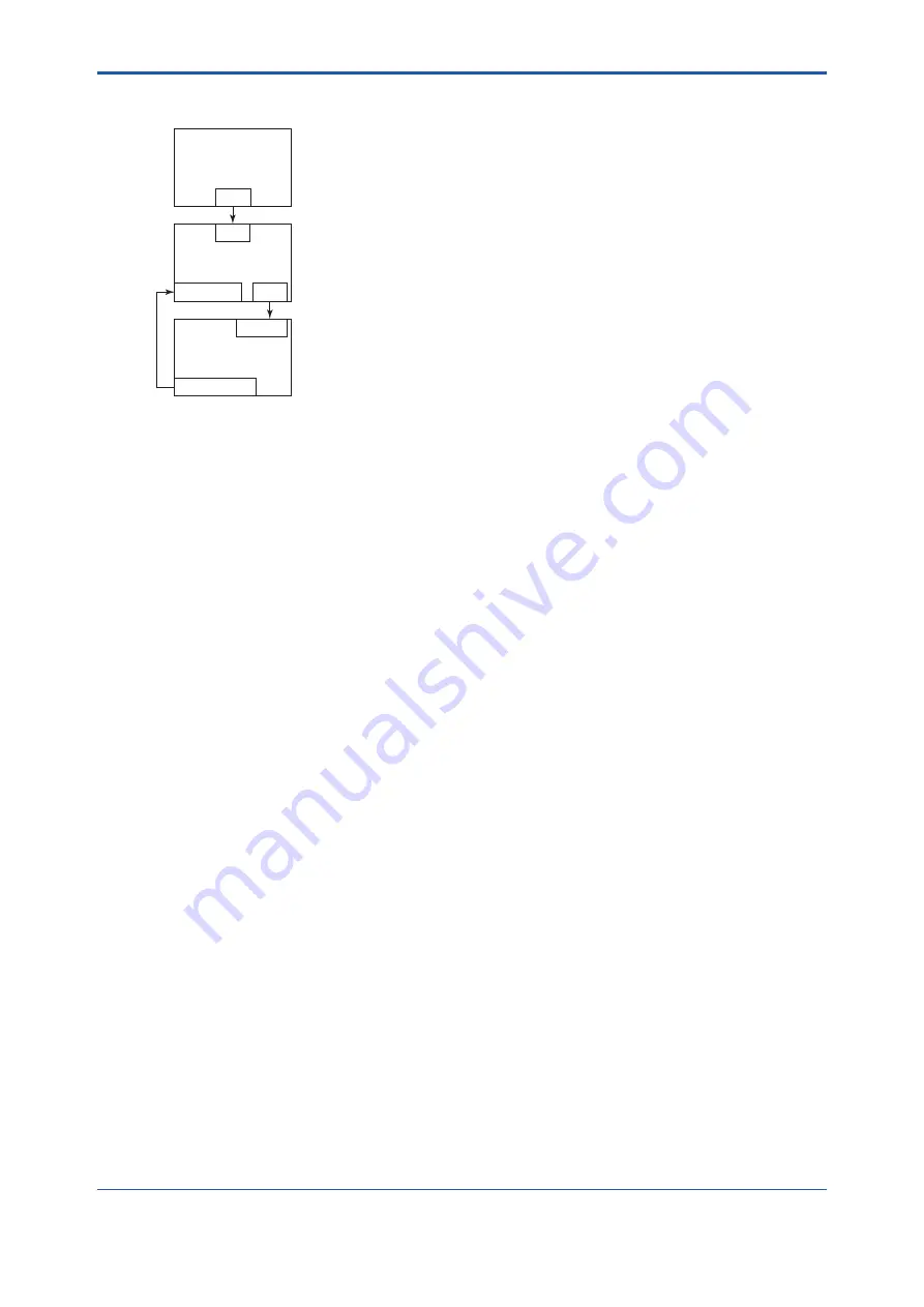
PID
BKCAL_IN
OUT
IN
AO
BKCAL_OUT
CAS_IN
AI
OUT
FA0106.ai
To use a simple PID control loop by combining a valve positioner (device with AO) with a sensor
device, the setting procedures for each block are explained based on the basic connection
example of PID.
(1) Connect the AI block and PID block of the sensor device, and the AO block of the valve
positioner as shown above.
(2) Set GAIN, RESET, and RATE parameters by setting the MODE_BLK target of the PID block
to O/S.
(3) Check that the value of MODE_BLK actual of the AI block is Auto.
(4) Set the MODE_BLK target of the AO block to Cas|Auto.
(5) Check that the value of BKCAL_IN status of the PID block is not BAD.
(6) Check that the value of IN status of the PID block is not BAD.
(7) Check that Auto is set to the permitted mode in MODE_BLK of the PID block.
(8) Set the MODE_BLK target of the PID block to Auto.
When finishing up to No. 8 with this setting, the PID block and AO block exchange the respective
information and initialize the cascade connection.
By following the above steps, the actual of MODE_BLK of the PID block changes to Auto and the
automatic PID control starts.


