
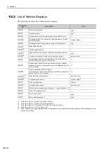
10.2 List of Parameters
10-29
10
Ap
pend
ix
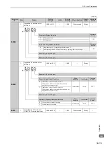
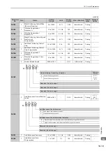
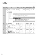
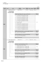
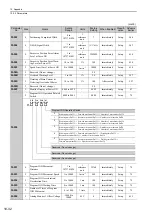
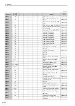
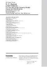
Pn50F
2
Output Signal Selection 2
0000 to 3333
−
0000
After restart
Setup
−
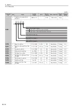
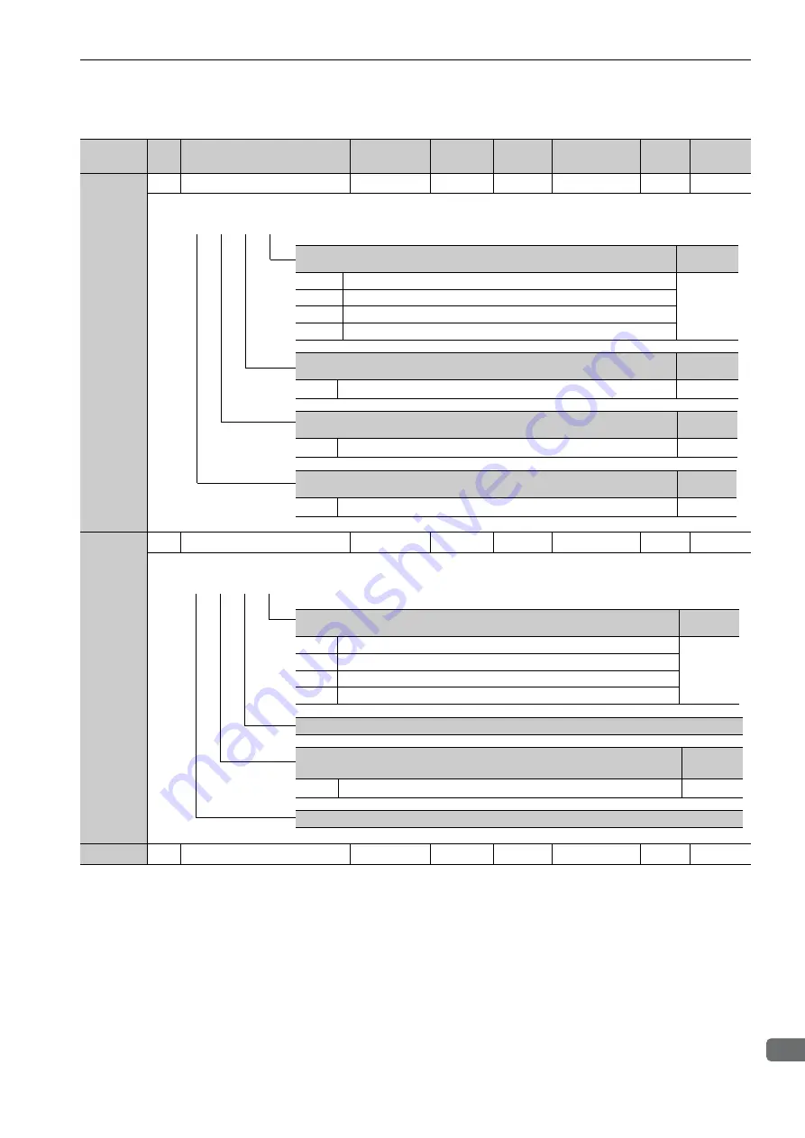
Pn510
2
Output Signal Selection 3
0000 to 0333
−
0000
After restart
Setup
−
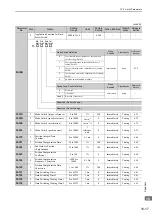
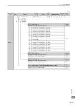
Pn511
2
Reserved (Do not change.)
−
−
8888
−
−
−
(cont’d)
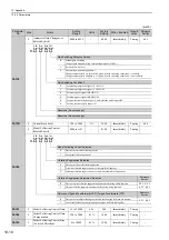
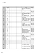
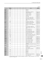
Parameter
No.
Size
Name
Setting
Range
Units
Factory
Setting
When Enabled Classifi-
cation
Reference
Section
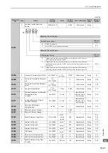
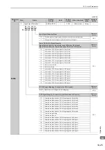
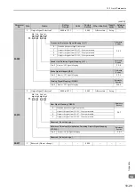
Torque Limit Detection Signal Mapping (/CLT)
Reference
Section
0
Disabled (the above signal is not used.)
5.8.5
1
Outputs the signal from CN1-25, -26 output terminal.
2
Outputs the signal from CN1-27, -28 output terminal.
3
Outputs the signal from CN1-29, -30 output terminal.
Speed Limit Detection Signal Mapping (/VLT)
Reference
Section
0 to 3
Same as /CLT Signal Mapping.
5.5.4
Brake Signal Mapping (/BK)
Reference
Section
0 to 3
Same as /CLT Signal Mapping.
5.2.4
Warning Signal Mapping (/WARN)
Reference
Section
0 to 3
Same as /CLT Signal Mapping.
5.10.2
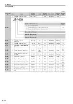
4th 3rd 2nd 1st
digit digit digit digit
n.
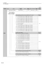
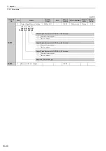
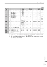
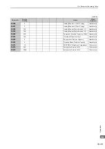
Near Signal Mapping (/NEAR)
Reference
Section
0
Disabled (the above signal is not used.)
5.4.7
1
Outputs the signal from CN1-25, -26 output terminal.
2
Outputs the signal from CN1-27, -28 output terminal.
3
Outputs the signal from CN1-29, -30 output terminal.
Reserved (Do not change.)
Reference Pulse Input Multiplication Switching Output Signal Mapping
(/PSELA)
Reference
Section
0 to 3
Same as /NEAR Signal Mapping.
5.4.3
Reserved (Do not change.)
4th 3rd 2nd 1st
digit digit digit digit
n.


