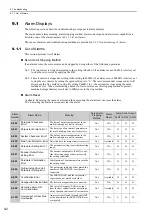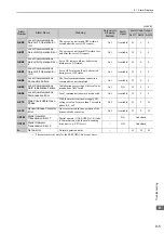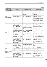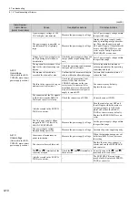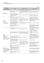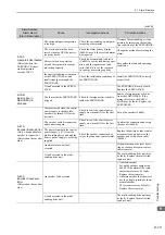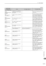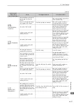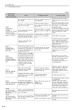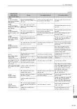
9.1 Alarm Displays
9-5
9
Trou
blesh
ooting
∗
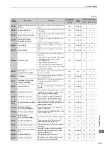
These alarms occur only for the SERVOPACKs or converters.
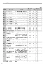
A.EE0
Local Communications
Servo OFF Operation Er-
ror 1
The servo was not turned OFF within 1
second after the servo OFF request.
Gr.1
Available
H
L
L
A.EE1
Local Communications
Servo ON Operation Error
1
The servo was not turned ON within 1 sec-
ond after the servo ON request.
Gr.1
Available
H
L
L
A.EE2
Local Communications
Servo ON Operation Error
2
Servo ON status could not be detected
during servo ON status.
Gr.1
Available
H
L
L
A.EE3
Local Communications
Servo OFF Operation Er-
ror 2
Servo OFF status could not be detected
during servo OFF status.
Gr.1
Available
H
L
L
A.EE4
Local Communications
Connection Failure
The local communications connection
command was not completed.
Gr.1
Available
H
L
L
A.EE5
Local Communications
ASIC Initialization Failure
Initialization processing of the local com-
munications ASIC failed.
Gr.1
N/A
H
L
L
A.EE6
Local Communications
Disconnection Error
Local communications was disconnected.
Gr.1
Available
H
L
L
A.F10
Main Circuit Cable Open
Phase
With the main circuit power supply ON,
voltage was low for more than 1 second in
phase R, S, or T.
Gr.2
Available
H
L
H
A.F30
Dynamic Brake Contactor
Error
An error occurred in the operation of the
dynamic brake contactor.
Gr.2
Available
H
L
H
CPF00
Digital Operator
Transmission Error 1
Digital operator (JUSP-OP05A-1-E) fails
to communicate with the multi-winding
drive unit (e.g., CPU error).
−
N/A
Undefined
CPF01
Digital Operator
Transmission Error 2
−
N/A
Undefined
A.
− −
Not an error
Normal operation status
−
−
H
H
H
(cont’d)
Alarm
Number
Alarm Name
Meaning
Servomotor
Stopping
Method
Alarm
Reset
Alarm Code Output
ALO1 ALO2 ALO3

