77
ATTENTION!
THE HIGH-PRESSURE FUEL PUMP IS LUBRI-
CATED BY THE OIL CIRCULATING INSIDE ITS HOUSING.
OIL PUMP
The oil pump is mounted on the rear side of the cylinder block
and can only be accessed when the flywheel housing is removed.
The oil pump safety valve is installed on the cylinder block
lower flange in the oil pump feed pipe and can be accessed when the
oil sump is removed.
The safety valve is designed to prevent damage to the oil pump
during start-up and operation of the cold engine when the engine oil
line may be filled with cold or viscous oil. The safety valve is adjusted
for the pressure downstream the oil pump 10 kgf/cm
2
. When this value
is exceeded, part of the oil from the oil feed line to the service module
goes to the oil sump.
OIL FILTER
The oil filter used on the engine is «MANN+HUMMEL» W
11 102. The filter is installed on the service module with the cap
looking down.
The filter is designed as a non-split cartridge with a metal
housing. The filter has a filter element, a safety bypass valve and a
non-return valve.
The bypass valve is used to protect the filter element against
destruction. It is adjusted for the differential pressure of 2,5 kgf/cm
2
upstream and downstream of the filter element. When this value is
exceeded, part of the oil is sent to the engine bypassing the filter
element. This can take place during start-up and operation of the cold
engine, when the oil is too viscous.
The non-return valve is used to prevent oil discharge from the
filter when the engine is not in operation and during the engine
maintenance when the filter is replaced.
The filter is installed on the service module by screwing it onto
the central clean oil outlet threaded pipe union screwed into the oil
filter housing. The connection is sealed by the filter outer rubber ring.
Summary of Contents for YMZ-536
Page 14: ...14 Fig 1 YMZ 536 engine right side view ...
Page 15: ...15 Fig 1 a YMZ 536 engine left side view ...
Page 16: ...16 Fig 1 b YMZ 536 10 engine right side view ...
Page 17: ...17 Fig 1 c YMZ 536 10 engine left side view ...
Page 18: ...18 Fig 1 d YMZ 536 30 engine right side view ...
Page 19: ...19 Fig 1 e YMZ 536 30 engine left side view ...
Page 20: ...20 Fig 1 f YMZ 5362 engine right side view ...
Page 21: ...21 Fig 1 g YMZ 5362 engine left side view ...
Page 22: ...22 Fig 1 h YMZ 53602 engine right side view ...
Page 23: ...23 Fig 1 i YMZ 53602 engine left side view ...
Page 51: ...51 Fig 10 Longitudinal section ...
Page 52: ...52 This page intentionally left blank ...
Page 96: ...96 Fig 33 High pressure fuel pump ...
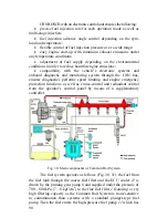
Page 99: ...99 Fig 35 Injector control The injector installation in the cylinder head is shown in Fig 36 ...
Page 168: ...168 NOTES ...

