65
ACCESSORY DRIVE GEARS
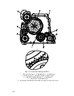
Accessories located in the rear part of the engine have a gear
drive (See Fig.16).
The gear on the crankshaft nose drives the camshaft gear. This
pair of gears is assembled according to the marks on the teeth (See
View
A
, Fig.16).
The camshaft gear drives the high-pressure fuel pump (HPFP,
or injection pump) and, through the intermediate gear, the air brake
compressor. These drives are assembled in an arbitrary manner; the
gears do not have any marks.
The gear on the crankshaft nose also drives the oil pump,
through the intermediate gear.
As the injection pump and the air compressor are located along
the cylinder block, the drive for all accessories is located in the gear
housing mounted on the block rear face. The gear housing has high-
precision bores where the HPFP, the air compressor and the
compressor intermediate gear are mounted. The camshaft and the oil
pump with the intermediate gear are located inside the gear housing
but in the cylinder block bores, so they do not touch the housing.
The gear drive is covered with the flywheel housing installed
on the gear housing.
Summary of Contents for YMZ-536
Page 14: ...14 Fig 1 YMZ 536 engine right side view ...
Page 15: ...15 Fig 1 a YMZ 536 engine left side view ...
Page 16: ...16 Fig 1 b YMZ 536 10 engine right side view ...
Page 17: ...17 Fig 1 c YMZ 536 10 engine left side view ...
Page 18: ...18 Fig 1 d YMZ 536 30 engine right side view ...
Page 19: ...19 Fig 1 e YMZ 536 30 engine left side view ...
Page 20: ...20 Fig 1 f YMZ 5362 engine right side view ...
Page 21: ...21 Fig 1 g YMZ 5362 engine left side view ...
Page 22: ...22 Fig 1 h YMZ 53602 engine right side view ...
Page 23: ...23 Fig 1 i YMZ 53602 engine left side view ...
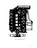
Page 51: ...51 Fig 10 Longitudinal section ...
Page 52: ...52 This page intentionally left blank ...
Page 96: ...96 Fig 33 High pressure fuel pump ...
Page 99: ...99 Fig 35 Injector control The injector installation in the cylinder head is shown in Fig 36 ...
Page 168: ...168 NOTES ...

