


86
1
2
3
4
5
Б
6
7
8
9
10
11
12
13
14
15
16
17
A
18
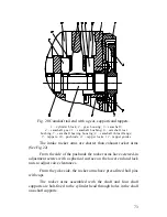
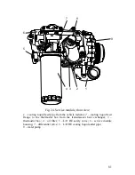
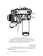
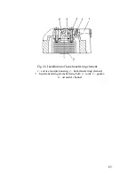
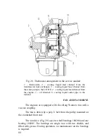
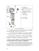
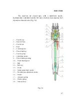
Fig. 27. Arrangement of channels in the service module:
1
– cooling liquid feed pipe from the vehicle radiator;
2
– suction cavity;
3
–
thermostat;
4
– oil outlet channel from the L/O HE element;
5
– L/O HE
element oil feed channel;
6
– oil filter;
7
– clean oil outlet from the oil filter;
8
– oil feed channel to the oil filter;
9
,
13
– L/O HE bypass channels;
10
,
11
–
oil feed channel from the block;
12
– service module housing;
13
– water
pump inlet pipe;
14
– water pump volute;
15
– water pump housing;
16
– water
pump pulley;
17
– water pump drive spindle;
18
– drain hole A – end seal (see
Fig.
25);B – L/O HE safety valve (see Fig. 27a)
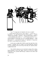
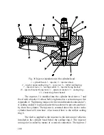
In the service module the L/O HE is open, but when the service
module is mounted onto the engine, the heat-transferring element
becomes confined in the closed cavity formed by the module and the
cylinder block wall.
The L/O HE element receives the whole volume of the cooling
liquid supplied by the water pump. After the L/O HE, the cooling
liquid goes to the cylinder head through 2 channels in the block and
cylinder head.
Summary of Contents for YMZ-536
Page 14: ...14 Fig 1 YMZ 536 engine right side view ...
Page 15: ...15 Fig 1 a YMZ 536 engine left side view ...
Page 16: ...16 Fig 1 b YMZ 536 10 engine right side view ...
Page 17: ...17 Fig 1 c YMZ 536 10 engine left side view ...
Page 18: ...18 Fig 1 d YMZ 536 30 engine right side view ...
Page 19: ...19 Fig 1 e YMZ 536 30 engine left side view ...
Page 20: ...20 Fig 1 f YMZ 5362 engine right side view ...
Page 21: ...21 Fig 1 g YMZ 5362 engine left side view ...
Page 22: ...22 Fig 1 h YMZ 53602 engine right side view ...
Page 23: ...23 Fig 1 i YMZ 53602 engine left side view ...
Page 51: ...51 Fig 10 Longitudinal section ...
Page 52: ...52 This page intentionally left blank ...
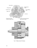
Page 96: ...96 Fig 33 High pressure fuel pump ...
Page 99: ...99 Fig 35 Injector control The injector installation in the cylinder head is shown in Fig 36 ...
Page 168: ...168 NOTES ...