
71
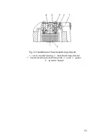
VALVE TRAIN
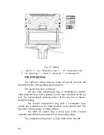
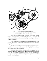
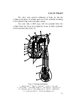
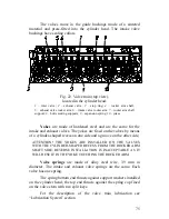
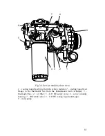
The valve train controls admission of fresh air into the
cylinders and release of exhaust gases out of the cylinders according
to the cylinder firing order and engine strokes.
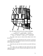
The valve train is OHV type, with the camshaft below the
cylinder head; the valves are actuated by means of lifters, pushrods,
rocker arms and yokes (Fig. 19).
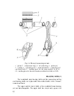
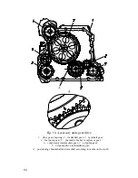
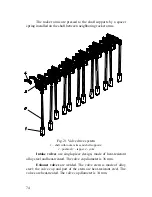
Fig. 19 Timing mechanism
1
– camshaft cam;
2
– tappet;
3
– pushrod;
4
– valves;
5
– valve seat;
6
– valve guide;
7
– valve spring washer;
8
– valve spring;
9
– cup-type seal;
10
– valve split cone;
11
– valve spring cap;
12
– yoke;
13
– rocker arm;
14
– rocker arm shaft;
15
– rocker arm adjusting screw
Summary of Contents for YMZ-536
Page 14: ...14 Fig 1 YMZ 536 engine right side view ...
Page 15: ...15 Fig 1 a YMZ 536 engine left side view ...
Page 16: ...16 Fig 1 b YMZ 536 10 engine right side view ...
Page 17: ...17 Fig 1 c YMZ 536 10 engine left side view ...
Page 18: ...18 Fig 1 d YMZ 536 30 engine right side view ...
Page 19: ...19 Fig 1 e YMZ 536 30 engine left side view ...
Page 20: ...20 Fig 1 f YMZ 5362 engine right side view ...
Page 21: ...21 Fig 1 g YMZ 5362 engine left side view ...
Page 22: ...22 Fig 1 h YMZ 53602 engine right side view ...
Page 23: ...23 Fig 1 i YMZ 53602 engine left side view ...
Page 51: ...51 Fig 10 Longitudinal section ...
Page 52: ...52 This page intentionally left blank ...
Page 96: ...96 Fig 33 High pressure fuel pump ...
Page 99: ...99 Fig 35 Injector control The injector installation in the cylinder head is shown in Fig 36 ...
Page 168: ...168 NOTES ...