104
CRANKCASE VENTILATION SYSTEM
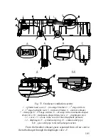
The crankcase ventilation system is a closed-type system (see
Fig. 37).
During the engine operation some amount of exhaust gases
from the cylinders enter the crankcase where they are mixed with oil
mist and sent to the turbocharger suction.
To prevent oil coking in the turbocharger, crankcase gases are
separated from oil in the breather
2
.
The two-stage breather
2
is incorporated into the plastic cover
of the cylinder head 1.
The first preliminary cleaning stage is a complex labyrinth with
swirlers 3 at the inlet and a hydraulic lock
4
at the outlet through
which the separated oil is drained to the cylinder head. The hydraulic
lock is designed as two cylinders
5
and
6
, one inserted into the other,
with a drain pipe
7
in the center. The drain pipe height maintains the
required drain oil column exceeding the pressure of the crankcase
gases.
The second fine cleaning stage is also designed as a complex
labyrinth with swirlers
8
. At the end of the labyrinth there is an oil
sump
9
with a mushroom-shaped drain valve
10
.
Summary of Contents for YMZ-536
Page 14: ...14 Fig 1 YMZ 536 engine right side view ...
Page 15: ...15 Fig 1 a YMZ 536 engine left side view ...
Page 16: ...16 Fig 1 b YMZ 536 10 engine right side view ...
Page 17: ...17 Fig 1 c YMZ 536 10 engine left side view ...
Page 18: ...18 Fig 1 d YMZ 536 30 engine right side view ...
Page 19: ...19 Fig 1 e YMZ 536 30 engine left side view ...
Page 20: ...20 Fig 1 f YMZ 5362 engine right side view ...
Page 21: ...21 Fig 1 g YMZ 5362 engine left side view ...
Page 22: ...22 Fig 1 h YMZ 53602 engine right side view ...
Page 23: ...23 Fig 1 i YMZ 53602 engine left side view ...
Page 51: ...51 Fig 10 Longitudinal section ...
Page 52: ...52 This page intentionally left blank ...
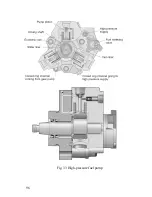
Page 96: ...96 Fig 33 High pressure fuel pump ...
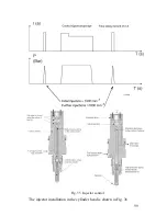
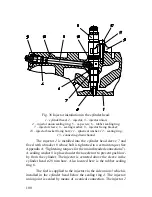
Page 99: ...99 Fig 35 Injector control The injector installation in the cylinder head is shown in Fig 36 ...
Page 168: ...168 NOTES ...

