56
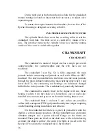
On the right side at the bottom there is a hole for the crankshaft
manual turning tool and an inspection hole necessary to adjust valve
expansion gaps.
To ensure the engine/transmission interface, the rear face of the
flywheel housing is designed according to SAE-1.
CYLINDER BLOCK FRONT COVER
The cylinder block front cover has a sealing collar to seal the
crankshaft front butt. The front cover is centered by means of two
pins. The interface between the cylinder block face and the mating
surface of the cover is sealed with a gasket.
CRANKSHAFT
CRANKSHAFT
The crankshaft is made of forged steel as a single piece with
counterweights; the counterweights and the web faces are not
machined.
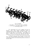
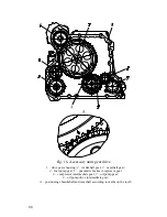
The crankshaft 3 (see Fig. 12) is fully supported; the main
journals and the connecting rod journals as well as the fillets are HFC-
hardened. The shaft is installed into the block onto the main journals
through the main sliding bearings (the main bearing upper shell 2 and
lower shell 7); the connecting rod bearings are lubricated through
drilled holes in the journals. The crankshaft is dynamically balanced.
The crankshaft is axially fixed in the engine with two thrust
bearing washers 6 (in the shape of a horseshoe), one on each side,
installed into recesses and grooves on the main bearing thrust cover.
The crankshaft front 1 and rear 5 seal collars are petal-like
collars with corrugated PTFE (polytetrafluorethylene) edges requiring
careful handling during installation and removal.
On the crankshaft tail there is a gear (4) press-fitted onto the
shaft in a certain angular position. On the crankshaft nose a torsional
vibration damper and a power take-off flange (at the front) are
mounted. These parts are fixed on the shaft nose with six bolts having
an inner star-shaped surface; the same type bolts are used to fix the
flywheel. Fixed onto the crankshaft tail is the flywheel.
Summary of Contents for YMZ-536
Page 14: ...14 Fig 1 YMZ 536 engine right side view ...
Page 15: ...15 Fig 1 a YMZ 536 engine left side view ...
Page 16: ...16 Fig 1 b YMZ 536 10 engine right side view ...
Page 17: ...17 Fig 1 c YMZ 536 10 engine left side view ...
Page 18: ...18 Fig 1 d YMZ 536 30 engine right side view ...
Page 19: ...19 Fig 1 e YMZ 536 30 engine left side view ...
Page 20: ...20 Fig 1 f YMZ 5362 engine right side view ...
Page 21: ...21 Fig 1 g YMZ 5362 engine left side view ...
Page 22: ...22 Fig 1 h YMZ 53602 engine right side view ...
Page 23: ...23 Fig 1 i YMZ 53602 engine left side view ...
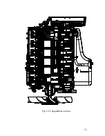
Page 51: ...51 Fig 10 Longitudinal section ...
Page 52: ...52 This page intentionally left blank ...
Page 96: ...96 Fig 33 High pressure fuel pump ...
Page 99: ...99 Fig 35 Injector control The injector installation in the cylinder head is shown in Fig 36 ...
Page 168: ...168 NOTES ...

