


92
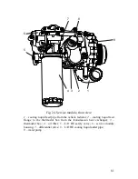
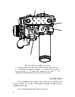
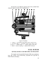
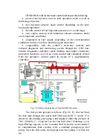
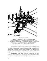
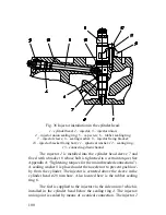
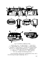
Fig. 31 Fuel system:
1
– injector;
2
– side union;
3
– rail;
4
– high-pressure pipes;
5
– HP fuel pump pipe;
6
– HP fuel pump with a low-pressure pump;
7
– priming pump fuel feed pipe;
8
– HP fuel pump feed pipe;
9
– engine fuel
feed pipe;
10
– engine fuel drain pipe;
11
– filter fuel feed pipe;
12
– fine fuel filter;
13
- Electronic Control Unit (ECU)
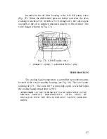
The electronic engine control system ensures self-diagnostics
of the ECU, transmitters (sensors) and some other vehicle devices.
When any deviations in the engine operation are detected, the
malfunction indicator lamp in the driver’s cabin turns on. In this case
apply to the service station to identify the cause of the trouble.
ATTENTION!
THE FUEL SYSTEM HARDWARE IS NOT
SUBJECT TO MAINTENANCE. IN CASE OF ANY FAILURE RELATED
TO THE FUEL SYSTEM, APPLY TO THE SERVICE STATION.
Summary of Contents for YMZ-536
Page 14: ...14 Fig 1 YMZ 536 engine right side view ...
Page 15: ...15 Fig 1 a YMZ 536 engine left side view ...
Page 16: ...16 Fig 1 b YMZ 536 10 engine right side view ...
Page 17: ...17 Fig 1 c YMZ 536 10 engine left side view ...
Page 18: ...18 Fig 1 d YMZ 536 30 engine right side view ...
Page 19: ...19 Fig 1 e YMZ 536 30 engine left side view ...
Page 20: ...20 Fig 1 f YMZ 5362 engine right side view ...
Page 21: ...21 Fig 1 g YMZ 5362 engine left side view ...
Page 22: ...22 Fig 1 h YMZ 53602 engine right side view ...
Page 23: ...23 Fig 1 i YMZ 53602 engine left side view ...
Page 51: ...51 Fig 10 Longitudinal section ...
Page 52: ...52 This page intentionally left blank ...
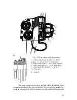
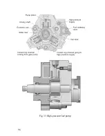
Page 96: ...96 Fig 33 High pressure fuel pump ...
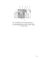
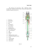
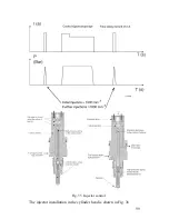
Page 99: ...99 Fig 35 Injector control The injector installation in the cylinder head is shown in Fig 36 ...
Page 168: ...168 NOTES ...