76
LUBRICATION SYSTEM
The engine lubrication system is a mixed-type wet-sump
system.
The oil pump sucks oil from the oil sump through the suction
pipe intake and a safety valve and supplies it to the system through the
in-line liquid-oil heat-exchanger (L/O HE) and the oil filter (OF).
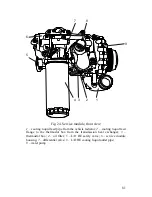
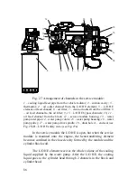
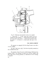
The L/O HE is installed in the service module housing which
also incorporates the lubrication system differential valve, the water
pump and the thermostat box. The service module is installed on the
front right side of the cylinder block. The oil filter is installed on the
service module.
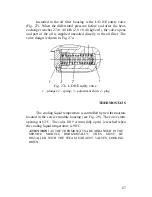
Installed in the oil filter housing is the L/O HE safety valve.
When the differential pressure before and after the heat-exchanger
reaches 274 ± 40 kPa (2.8 ± 0.40 kgf/cm
2
), the valve opens and part of
the oil is supplied uncooled directly to the oil filter.
The filtered oil is supplied to the main oil line of the cylinder
block located on the right side of the block through the channels in the
block and also to the cylinder head through the channel near the rear
side of the block.
In the cylinder head oil is supplied into the hollow rocker-arm
shaft through the rear shaft support, and from the shaft to the rocker-
arm bushings. From the bushings oil goes through the channel inside
the rocker arm to the ball stud and flows down to the valve yoke and
the valves.
The pushrod lifters located in the block are lubricated by oil
flowing down from the cylinder head.
The major part of oil from the cylinder head flows down the
vertical stiffness cavities in the block into the oil sump (see «Cylinder
Block and Cylinder Liners» section of this Manual).
The turbocharger and the air break compressor bearings are
lubricated by oil coming from exterior pipelines.
Accessory drive gears, camshaft cams, pushrod lifters (tappets)
and cylinder liners are lubricated by spraying.
Summary of Contents for YMZ-536
Page 14: ...14 Fig 1 YMZ 536 engine right side view ...
Page 15: ...15 Fig 1 a YMZ 536 engine left side view ...
Page 16: ...16 Fig 1 b YMZ 536 10 engine right side view ...
Page 17: ...17 Fig 1 c YMZ 536 10 engine left side view ...
Page 18: ...18 Fig 1 d YMZ 536 30 engine right side view ...
Page 19: ...19 Fig 1 e YMZ 536 30 engine left side view ...
Page 20: ...20 Fig 1 f YMZ 5362 engine right side view ...
Page 21: ...21 Fig 1 g YMZ 5362 engine left side view ...
Page 22: ...22 Fig 1 h YMZ 53602 engine right side view ...
Page 23: ...23 Fig 1 i YMZ 53602 engine left side view ...
Page 51: ...51 Fig 10 Longitudinal section ...
Page 52: ...52 This page intentionally left blank ...
Page 96: ...96 Fig 33 High pressure fuel pump ...
Page 99: ...99 Fig 35 Injector control The injector installation in the cylinder head is shown in Fig 36 ...
Page 168: ...168 NOTES ...

