87
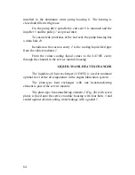
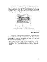
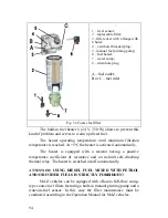
Installed in the oil filter housing is the L/O HE safety valve
(Fig. 27). When the differential pressure before and after the heat-
exchanger reaches 274 ± 40 kPa (2,8 ± 0,40 kgf/cm
2
), the valve opens
and part of the oil is supplied uncooled directly to the oil filter. The
valve design is shown in Fig. 27a.
Fig. 27
а
. L/O HE safety valve:
1
– plunger;
2
– spring;
3
– adjustment shim;
4
- plug
THERMOSTATS
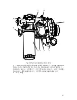
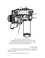
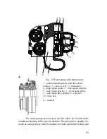
The cooling liquid temperature is controlled by two thermostats
located in the service module housing (see Fig. 28). The valve starts
opening at 83
С
. The valve lift 9.4 mm (fully open) is reached when
the cooling liquid temperature is 98
С
.
ATTENTION!
AS THE THERMOSTATS ARE ARRANGED IN THE
SERVICE MODULE HORIZONTALLY, THEY MUST BE
INSTALLED WITH THE STEAM EXHAUST VALVES LOOKING
DOWN.
Summary of Contents for YMZ-536
Page 14: ...14 Fig 1 YMZ 536 engine right side view ...
Page 15: ...15 Fig 1 a YMZ 536 engine left side view ...
Page 16: ...16 Fig 1 b YMZ 536 10 engine right side view ...
Page 17: ...17 Fig 1 c YMZ 536 10 engine left side view ...
Page 18: ...18 Fig 1 d YMZ 536 30 engine right side view ...
Page 19: ...19 Fig 1 e YMZ 536 30 engine left side view ...
Page 20: ...20 Fig 1 f YMZ 5362 engine right side view ...
Page 21: ...21 Fig 1 g YMZ 5362 engine left side view ...
Page 22: ...22 Fig 1 h YMZ 53602 engine right side view ...
Page 23: ...23 Fig 1 i YMZ 53602 engine left side view ...
Page 51: ...51 Fig 10 Longitudinal section ...
Page 52: ...52 This page intentionally left blank ...
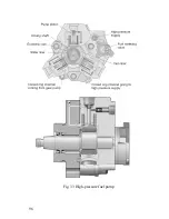
Page 96: ...96 Fig 33 High pressure fuel pump ...
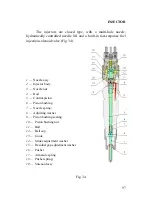
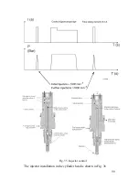
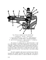
Page 99: ...99 Fig 35 Injector control The injector installation in the cylinder head is shown in Fig 36 ...
Page 168: ...168 NOTES ...

