


106
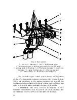
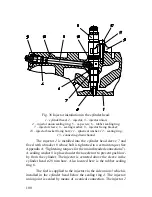
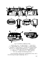
Through the
2mm hole
13
in the cover
12
atmospheric
pressure is applied onto the diaphragm. From below, on the crankcase
gases side the diaphragm
14
is spring-loaded by the cylindrical spring
15
.
The crankcase gases are removed via the circular slot between
the diaphragm and the central outlet pipe
16
.
When the turbocharger sucks from the engine an excessive
amount of crankcase gases, underpressure is created inside the engine
and the diaphragm 14 under the action of atmospheric pressure sits
down onto the central outlet pipe 16 thus closing it.
ATTENTION!
THE CRANKCASE VENTILATION SYSTEM DOES
NOT REQUIRE MAINTENANCE AND
IS NOT MEANT TO BE
DISASSEMBLED.
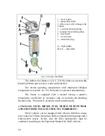
BEFORE STARTING THE NEW OR REPAIRED
ENGINE, FILL THE 1
ST
STAGE HYDRAULIC LOCK
4
(VIEW B)
WITH 2 – 3 cm
3
OF THE ENGINE OIL USED IN THE ENGINE.
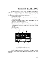
Summary of Contents for YMZ-536
Page 14: ...14 Fig 1 YMZ 536 engine right side view ...
Page 15: ...15 Fig 1 a YMZ 536 engine left side view ...
Page 16: ...16 Fig 1 b YMZ 536 10 engine right side view ...
Page 17: ...17 Fig 1 c YMZ 536 10 engine left side view ...
Page 18: ...18 Fig 1 d YMZ 536 30 engine right side view ...
Page 19: ...19 Fig 1 e YMZ 536 30 engine left side view ...
Page 20: ...20 Fig 1 f YMZ 5362 engine right side view ...
Page 21: ...21 Fig 1 g YMZ 5362 engine left side view ...
Page 22: ...22 Fig 1 h YMZ 53602 engine right side view ...
Page 23: ...23 Fig 1 i YMZ 53602 engine left side view ...
Page 51: ...51 Fig 10 Longitudinal section ...
Page 52: ...52 This page intentionally left blank ...
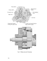
Page 96: ...96 Fig 33 High pressure fuel pump ...
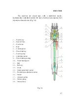
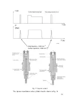
Page 99: ...99 Fig 35 Injector control The injector installation in the cylinder head is shown in Fig 36 ...
Page 168: ...168 NOTES ...