


105
А
Б
В
Г
Д
Е
-
Е
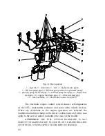
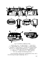
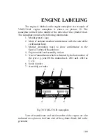
Fig. 37. Crankcase ventilation system:
1
– cylinder head cover;
2
– two-stage breather;
3
– 1
st
stage swirlers;
4
– 1
st
stage hydraulic lock;
5
– internal cylinder;
6
– external cylinder;
7
– drain pipe; 8 – 2
nd
stage swirlers; 9 – oil sump with a mushroom-shaped
drain valve; 10 – mushroom-shaped drain valve;
11
– diaphragm valve;
12
– cover;
13
– a hole in the cover for the atmospheric pressure;
14
– diaphragm;
15
– cylindrical spring;
16
– central outlet pipe;
Е
-
Е
– gas outlet pipe to the turbocharger suction
From the breather exhaust gases separated from oil are sent to
the turbocharger through the diaphragm valve
11
.
Summary of Contents for YMZ-536
Page 14: ...14 Fig 1 YMZ 536 engine right side view ...
Page 15: ...15 Fig 1 a YMZ 536 engine left side view ...
Page 16: ...16 Fig 1 b YMZ 536 10 engine right side view ...
Page 17: ...17 Fig 1 c YMZ 536 10 engine left side view ...
Page 18: ...18 Fig 1 d YMZ 536 30 engine right side view ...
Page 19: ...19 Fig 1 e YMZ 536 30 engine left side view ...
Page 20: ...20 Fig 1 f YMZ 5362 engine right side view ...
Page 21: ...21 Fig 1 g YMZ 5362 engine left side view ...
Page 22: ...22 Fig 1 h YMZ 53602 engine right side view ...
Page 23: ...23 Fig 1 i YMZ 53602 engine left side view ...
Page 51: ...51 Fig 10 Longitudinal section ...
Page 52: ...52 This page intentionally left blank ...
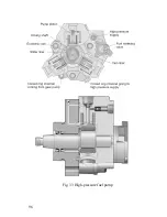
Page 96: ...96 Fig 33 High pressure fuel pump ...
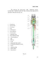
Page 99: ...99 Fig 35 Injector control The injector installation in the cylinder head is shown in Fig 36 ...
Page 168: ...168 NOTES ...