69
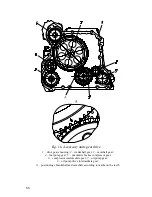
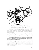
Fig. 17b Accessory drive belts (third option):
1
– crankshaft pulley and damper;
2
– tension roller;
3
– water pump pulley;
4
– belt;
8
– generator pulley
The belts are tensioned by automatic rollers with springs
inside; during operation no additional adjustment is required. All
rollers are the same, with a smooth pulley, operating on the outer
smooth belts surface.
The roller pulley incorporates a press-fitted ball bearing with
shields. The bearing is filled with grease for the whole period of the
engine lifetime.
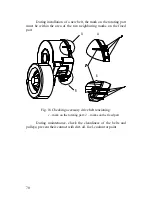
The fixed base of the roller has a special area with three marks,
and there is one mark on the rotating part (Fig. 18). The marks are
used to check belt stretch elongation.
In the operating position, the mark on the rotating part must be
within the area of the three marks on the fixed part. If it is outside the
area, the belt must be replaced. To remove the belt, compress the
spring of the automatic belt tensioning system by turning the roller
relative to the fixed base.
Summary of Contents for YMZ-536
Page 14: ...14 Fig 1 YMZ 536 engine right side view ...
Page 15: ...15 Fig 1 a YMZ 536 engine left side view ...
Page 16: ...16 Fig 1 b YMZ 536 10 engine right side view ...
Page 17: ...17 Fig 1 c YMZ 536 10 engine left side view ...
Page 18: ...18 Fig 1 d YMZ 536 30 engine right side view ...
Page 19: ...19 Fig 1 e YMZ 536 30 engine left side view ...
Page 20: ...20 Fig 1 f YMZ 5362 engine right side view ...
Page 21: ...21 Fig 1 g YMZ 5362 engine left side view ...
Page 22: ...22 Fig 1 h YMZ 53602 engine right side view ...
Page 23: ...23 Fig 1 i YMZ 53602 engine left side view ...
Page 51: ...51 Fig 10 Longitudinal section ...
Page 52: ...52 This page intentionally left blank ...
Page 96: ...96 Fig 33 High pressure fuel pump ...
Page 99: ...99 Fig 35 Injector control The injector installation in the cylinder head is shown in Fig 36 ...
Page 168: ...168 NOTES ...

