


129
1.
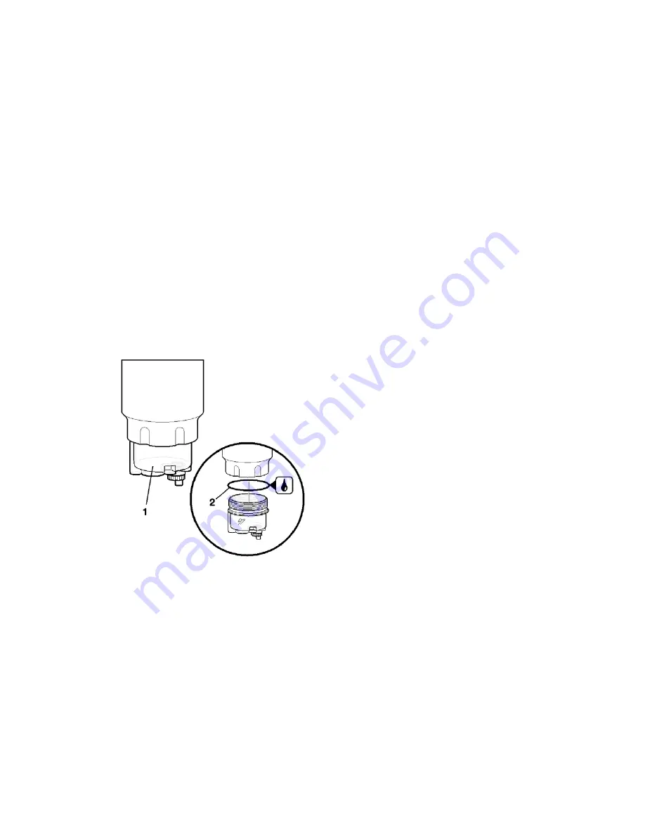
Switch off the engine
2.
Drain water from the water sump
3.
Unscrew the water sump
1
(Fig. 41) by means of the tools
from the package of the new sump. While doing this, hold the
replaceable filter in position so that it should not be
unscrewed.
4.
Lubricate the sealing ring
2
of the new sump with motor oil
5.
Screw the water sump by hand.
6.
Place the special-purpose wrench on the torque wrench and
torque the water sump to 20Nm (2 kgf·m). While doing this,
hold the replaceable filter in position so that it should not be
over-tightened.
7.
Check if the screw plug of the drain hole is in.
8.
Flush the fuel system using a manual feed pump.
9.
Start the engine and check the sump for leakage.
Fig. 41. Change of water sump
1
– water sump;
2
– sealing ring
CHANGE OF COARSE FUEL FILTER
1.
Switch the engine off
2.
Unscrew the water sump and check it for damage in case it
can be reused. Screw the sump on the new filtering element (see
“Change of water sump” above)
3.
Remove the old replaceable filter
2
(Fig. 32). The old filter
may be seated tight in the filter housing. Use proper tools.
Summary of Contents for YMZ-536
Page 14: ...14 Fig 1 YMZ 536 engine right side view ...
Page 15: ...15 Fig 1 a YMZ 536 engine left side view ...
Page 16: ...16 Fig 1 b YMZ 536 10 engine right side view ...
Page 17: ...17 Fig 1 c YMZ 536 10 engine left side view ...
Page 18: ...18 Fig 1 d YMZ 536 30 engine right side view ...
Page 19: ...19 Fig 1 e YMZ 536 30 engine left side view ...
Page 20: ...20 Fig 1 f YMZ 5362 engine right side view ...
Page 21: ...21 Fig 1 g YMZ 5362 engine left side view ...
Page 22: ...22 Fig 1 h YMZ 53602 engine right side view ...
Page 23: ...23 Fig 1 i YMZ 53602 engine left side view ...
Page 51: ...51 Fig 10 Longitudinal section ...
Page 52: ...52 This page intentionally left blank ...
Page 96: ...96 Fig 33 High pressure fuel pump ...
Page 99: ...99 Fig 35 Injector control The injector installation in the cylinder head is shown in Fig 36 ...
Page 168: ...168 NOTES ...