V
oice mode
Song mode
P
a
tt
er
n mode
Mixing mode
Mast
er mode
Utility mode
F
ile mode
P
erf
or
mance
mode
Sampling
mode 1
Sampling
mode 2
R
e
fe
rence
MOTIF XF Reference Manual
219
System Settings (Utility mode, etc.)
In the Utility mode, you can set parameters that apply to the entire system of the MOTIF XF. To enter the Utility mode, press
the [UTILITY] button. Pressing the [EXIT] button returns to the original display. For system settings related to the sequencer
in Song/Pattern/Arpeggio playback, call up the Sequencer Setup display by pressing the [SEQ SETUP] button in the Song/
Pattern/Performance mode.
Basic Procedure in the Utility mode
1
Enter the Utility mode.
Press the [UTILITY] button to enter the Utility mode.
(The indicator lights.)
2
Call up the desired display.
Note the tab menus of the [F1] – [F6] and [SF1] – [SF5]
buttons to find the desired function, then press the
relevant button to call up the desired display.
3
Set the desired parameter.
Move the cursor to each parameter, then set the value
by using the data dial, [INC/YES] and [DEC/NO] button.
NOTICE
When “Press [ENTER] to set” is shown on the display, make
sure to press the [ENTER] button before going to the next step.
If you do not, the settings will not be stored, even if you press
the [STORE] button in the next step.
4
Press the [STORE] button to store the Utility
setting and Sequencer Setup to internal
memory.
NOTICE
All Utility settings will be lost when the power is turned off
without storing.
n
The parameter settings in the Utility displays and
Sequencer Setup displays are treated and stored as a
single unit. This means that when you execute the Store
operation in the Utility mode, the settings in the Sequencer
Setup displays are also stored, and vice versa.
5
Press the [EXIT] button to exit from the Utility
mode to the original mode.
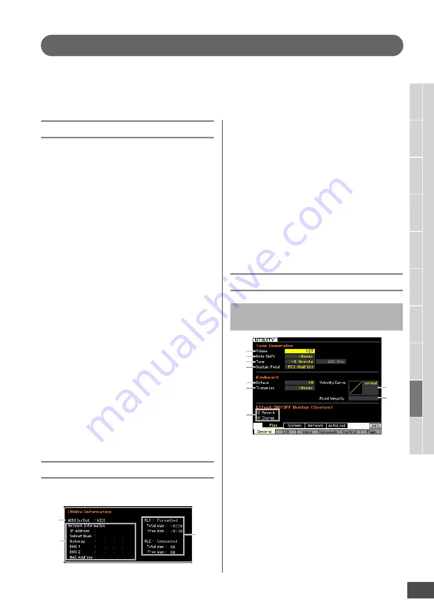
System Information—[SF6] INFO
This display indicates the MIDI IN/OUT settings and
Network settings. This display cannot be edited.
1
MIDI IN/OUT
(Indication only)
Indicates the hardware terminal via which the MIDI data is
input or output. The related parameters can be set in the
MIDI display (page 228).
2
Network Information
Indicates the network settings. The related parameters can
be set in the Network display (page 221).
3
FL1/FL2
(indication only)
Indicates whether or not the optional Flash Memory
Expansion Module FL512M/FL1024M has been installed. In
addition, when installed, this section indicates the memory
size and information whether or not the Module has already
been formatted.
General Settings—[F1] General
Tone Generator
From this section, you can make overall settings for the
internal tone generator. The settings here only affect the
internal tone generator block. The MIDI output will not be
affected.
1
Volume
Determines the overall volume of the instrument.
Settings:
0 – 127
2
Note Shift
Determines the amount (in semitones) by which the pitch of
all notes is shifted.
Settings:
-24 semi – +0 semi – +24 semi
1
2
3
Tone Generator and Keyboard settings
—[SF1] Play
1
2
3
4
5
6
9
7
8


