background image

2-65

INSP

ADJ

FRONT SUSPENSION

Compression damping force adjustment (FX10)

The compression damping force can be adjusted
by turning the adjusting knob 

1

.

* With the adjusting knob fully turned lightly in

direction 

a


CAUTION:

• Do not continue to turn the adjusting knob in

direction 

a

 after it stops. The shock absorber

can be damaged and compression damping
force adjustments cannot be made.

• Do not turn the adjusting knob in direction 

b

more than 12 clicks. Even if the adjusting
knob is continually turned after 12 clicks,
there will be no change in the compression
damping force.

• Be sure to stop the adjusting knob at a posi-

tion where there is a click.

• The damping forces for the left and right ski

shock absorbers must be adjusted to the
same settings. Uneven settings can cause
poor handling and loss of stability.

Adjusting 
knob 
position

12 clicks out

6 clicks out

2 clicks out

Minimum

Standard

Maximum

Direction 

b

 Direction 

a


Compres-
sion damp-
ing force

Soft 

 Hard

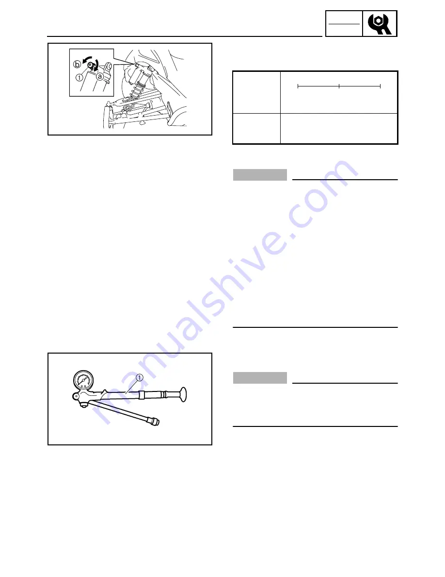
Air pressure adjustment (FX10RT/FX10RTR/
FX10RTRA)

CAUTION:

The left and right shock absorber air pressure
must be set to the same setting. Uneven set-
tings can cause poor handling and loss of sta-
bility.

This snowmobile is equipped with FOX shock
absorbers as standard equipment.
The air pressure of the shock absorbers can be
adjusted using the shock absorber pump 

1

included with your snowmobile.

Summary of Contents for FX10X 2008

Page 1: ...SERVICE MANUAL FX10X FX10RTX FX10RTRX FX10RTRAX FX10MTX FX10MTRX FX10MTRAX LIT 12618 02 69 8GL 28197 10 PRINTED ON RECYCLED PAPER PRINTED IN U S A 2007 07 CR E YAMAHA MOTOR CO LTD 2008 ...

Page 2: ......

Page 3: ... death to the snowmobile opera tor a bystander or a person inspecting or repairing the snowmobile A CAUTION indicates special precautions that must be taken to avoid damage to the snowmobile A NOTE provides key information that can make procedures easier or clearer MANUAL FORMAT All of the procedures in this manual are organized in a sequential step by step format The informa tion has been compile...

Page 4: ...rance D Engine speed E Special tool F Electrical data Ω V A Illustrated symbols G to R in the exploded diagram indicate grade of lubricant and location of lubrica tion point G Apply locking agent LOCTITE H Apply Yamabond No 5 I Apply engine oil J Apply gear oil K Apply molybdenum disulfide oil L Apply brake fluid M Apply wheel bearing grease N Apply low temperature lithium soap based grease O Appl...

Page 5: ...RAL INFORMATION GEN INFO 1 PERIODIC INSPECTION AND ADJUSTMENT INSP ADJ 2 CHASSIS CHAS 3 POWER TRAIN POWR TR 4 ENGINE ENG 5 COOLING SYSTEM COOL 6 FUEL INJECTION SYSTEM FI 7 ELECTRICAL ELEC 8 SPECIFICATIONS SPEC 9 ...

Page 6: ... LEVEL INSPECTION 2 19 ENGINE OIL REPLACEMENT 2 20 CYLINDER HEAD BREATHER HOSE INSPECTION 2 23 THROTTLE BODY JOINTS INSPECTION 2 23 CHECKING THE AIR FILTER ELEMENT 2 23 EXHAUST SYSTEM INSPECTION 2 25 POWER TRAIN 2 26 SHEAVE OFFSET ADJUSTMENT 2 26 DRIVE V BELT 2 28 ENGAGEMENT SPEED CHECK 2 30 PARKING BRAKE PAD INSPECTION 2 31 PARKING BRAKE ADJUSTMENT 2 31 BRAKE FLUID LEVEL INSPECTION 2 32 BRAKE PAD...

Page 7: ...E CALIPER INSPECTION AND REPAIR 4 37 BRAKE CALIPER ASSEMBLY 4 38 BRAKE CALIPER INSTALLATION 4 38 BRAKE MASTER CYLINDER 4 39 INSPECTION 4 41 BRAKE MASTER CYLINDER ASSEMBLY 4 41 INSTALLATION 4 42 SLIDE RAIL SUSPENSION 4 43 FX10 4 43 FX10RT FX10RTR FX10RTRA 4 49 FX10MT FX10MTR FX10MTRA 4 55 HANDLING NOTES 4 61 REMOVAL 4 61 INSPECTION 4 61 ASSEMBLY 4 62 INSTALLATION 4 66 FRONT AXLE AND TRACK 4 67 INSP...

Page 8: ...SURE SWITCH 7 26 INTAKE AIR TEMPERATURE SENSOR 7 26 ISC IDLE SPEED CONTROL UNIT 7 27 AIR FILTER CASE 7 28 THROTTLE BODY 7 29 INJECTORS 7 30 REMOVAL 7 32 INSPECTION 7 32 FUEL PRESSURE INSPECTION 7 33 INSPECTION AND ADJUSTMENT 7 34 CHAPTER 8 ELECTRICAL SWITCH INSPECTION 8 1 SWITCH INSPECTION 8 1 INSPECTING A SWITCH SHOWN IN THE MANUAL 8 1 IGNITION SYSTEM 8 2 CIRCUIT DIAGRAM 8 2 TROUBLESHOOTING 8 4 I...

Page 9: ...8 45 GRIP THUMB WARMER ADJUSTMENT SWITCH 8 45 COOLING SYSTEM 8 46 CIRCUIT DIAGRAM 8 46 TROUBLESHOOTING 8 48 RADIATOR FAN MOTOR 8 49 RADIATOR FAN MOTOR RELAY 8 49 CHAPTER 9 SPECIFICATIONS GENERAL SPECIFICATIONS 9 1 MAINTENANCE SPECIFICATIONS 9 5 ENGINE 9 5 POWER TRAIN 9 10 CHASSIS 9 16 ELECTRICAL 9 18 TIGHTENING TORQUE 9 20 ENGINE 9 20 POWER TRAIN 9 22 CHASSIS 9 25 GENERAL TORQUE SPECIFICATIONS 9 2...

Page 10: ...erial number 1 is located on the right hand side of the frame just below the front of the seat ENGINE SERIAL NUMBER The engine serial number 1 is located on the right hand side of the crank case NOTE Designs and specifications are subject to change without notice 1 SNOWMOBILE IDENTIFICATION ...

Page 11: ...ts that have been mated through normal wear Mated parts must be reused or replaced as an assembly 4 During disassembly of the snowmobile clean all parts and place them in trays in the order of disassembly This will speed up assembly time and help ensure that all parts are reinstalled correctly 5 Keep all parts away from any source of fire 6 Be sure to keep to the tightening torque specifications W...

Page 12: ... marks or numbers facing outwards In other words the stamped letters must be on the side exposed to view When installing oil seals apply a light coating of low temperature lithium soap based grease to the seal lips Oil the bearings liberally when installing CAUTION Do not use compressed air to spin the bearings dry This causes damage to the surface of the bearings CIRCLIPS All circlips should be i...

Page 13: ...OR TUNE UP Dial indicator gauge P N YU A8428 Dial gauge P N 90890 03097 This gauge is used for runout measurements Angle gauge Use goods on the market This tool is used to tighten to specified angles Steering linkage alignment plate P N YS 01531 90890 01531 Locks steering column and pivot arm in place while adjusting the steering linkage for front end alignment FOR ENGINE SERVICE Piston pin puller...

Page 14: ... the oil filter cartridge Carburetor synchronizer P N YU 44456 Vacuum gauge P N 90890 03094 This tool is used to synchronize the throttle bodies Engine compression tester P N YU 33223 Compression gauge P N 90890 03081 This tool is used to measure engine compression Carburetor angle driver 2 P N 90890 03173 This tool is used to synchronize the throttle bodies Valve spring compressor P N YM 04019 90...

Page 15: ...ide remover ø4 5 P N 90890 04116 This tool is used to remove or install the valve guides Valve guide installer 4 5 mm P N YM 04117 Valve guide installer ø4 5 P N 90890 04117 This tool is used to install the valve guides Valve guide reamer 4 5 mm P N YM 04118 Valve guide reamer ø4 5 P N 90890 04118 This tool is used to rebore the new valve guides Valve lapping tool P N YM A8998 Valve lapper P N 908...

Page 16: ...CE Primary clutch holder P N YS 01880 A Sheave holder P N 90890 01701 This tool is used to hold the primary sheave and AC magneto rotor Primary sheave puller 18 mm P N YS 01881 A 1 YS 01881 1 2 90890 01898 This tool is used for removing the primary sheave Clutch spider separator P N YS 28890 C 90890 01711 This tool is used when disassembling and assembling the primary sheave Clutch separator adapt...

Page 17: ... N YM 03176 90890 03176 This tool is needed to measure fuel pressure Pressure gauge P N YU 03153 90890 03153 This tool is used to measure fuel pressure FOR ELECTRICAL SERVICE Analog pocket tester P N YU 03112 C Pocket tester P N 90890 03112 This instrument is necessary for checking the electrical components Engine tachometer P N YU 08036 C 90793 80009 This tool is used to check engine speed Model ...

Page 18: ...THE EMISSION CONTROL SYSTEM ITEM REMARKS INITIAL EVERY 1 month or 800 km 500 mi 40 hr Seasonally or 4000 km 2500 mi 200 hr Spark plugs Check condition Adjust gap and clean Replace if necessary Valve clearance Check and adjust valve clearance when engine is cold Every 40000 km 25000 mi Crankcase breather system Check breather hose for cracks or damage Replace if necessary Fuel filter Check conditio...

Page 19: ...for wear for secondary Replace if necessary Lubricate with specified grease Drive chain Check chain slack Adjust if necessary Initial at 500 km 300 mi and every 800 km 500 mi thereaf ter Drive chain oil Check oil level Change Brake and parking brake Adjust free play and or replace pads if necessary Change brake fluid See NOTE following this chart Control cables Make sure that operation is smooth L...

Page 20: ... of specification Regap Use a wire thickness gauge If necessary clean the spark plugs with a spark plug cleaner Standard spark plug NGK CR9E NGK Before installing a spark plug clean the gasket sur face and spark plug surface 5 Install Spark plugs NOTE Finger tighten a the spark plug before torquing b it to specification Spark plug gap 0 7 0 8 mm 0 028 0 031 in T R Spark plug 13 Nm 1 3 m kg 9 4 ft ...

Page 21: ...n the hissing sound has stopped press down on the cap while turning it counter clockwise to remove it 4 Place an open container under the thermostat outlet hose coolant reservoir hose and for FX10MT FX10MTR FX10MTRA only heat exchanger 5 Disconnect Thermostat outlet hose 2 Coolant reservoir hose 3 6 Remove Heat exchanger drain bolt 4 FX10MT FX10MTR FX10MTRA 7 Drain the coolant NOTE Lift up the tai...

Page 22: ...ng corrosion inhibi tors Coolant mixing ratio coolant water 3 2 60 40 Total amount FX10 FX10RT FX10RTR FX10RTRA 3 40 L 2 99 Imp qt 3 59 US qt FX10MT FX10MTR FX10MTRA 4 70 L 4 14 Imp qt 4 97 US qt 11 Inspect Cooling system Decrease of pressure leaks Repair as required Inspection steps Attach the cooling system tester 1 and adapter 2 to the radiator filler 3 Apply 100 kPa 1 0 kg cm2 14 psi Measure t...

Page 23: ... The heat exchanger will be warm to the touch FX10MT FX10MTR FX10MTRA È FX10MT FX10MTR FX10MTRA WARNING To avoid severe injury or death Make sure the snowmobile is securely sup ported with a suitable stand Do not exceed the clutch engagement speed Drive line damage and excessive V belt wear could occur or the snowmobile could unex pectedly move forward if the clutch engages Operate the engine only...

Page 24: ...o OIL TANK in CHAPTER 5 3 Remove Cylinder head cover Refer to CAMSHAFTS in CHAPTER 5 Timing mark accessing screw 1 Crankshaft end accessing screw 2 4 Measure Valve clearance Out of specification Adjust Checking steps Turn the crankshaft clockwise When piston 3 is at TDC on the compression stroke align the TDC mark a on the AC mag neto rotor with the mark b on the AC magneto cover NOTE TDC on the c...

Page 25: ...ith cylinder 3 at TDC turn the crankshaft clockwise as specified in the fol lowing table É Degrees that the crankshaft is turned clockwise Ê Cylinder Ë Combustion cycle Valve clearance measuring sequence Cylinder 3 2 1 Cylinder 2 120 Cylinder 1 240 1 5 Remove Intake camshaft Exhaust camshaft NOTE Refer to CAMSHAFTS in CHAPTER 5 When removing the timing chain and camshafts fasten a wire to the timi...

Page 26: ... from the following table NOTE The thickness a of each valve pad is marked in hundredths of millimeters on the side that touches the valve lifter Since valve pads of various sizes are originally installed the valve pad number must be rounded in order to reach the closest equivalent to the original Round off the original valve pad number according to the following table Valve lapper 90890 04101 Val...

Page 27: ...mber of the original valve pad and the measured valve clearance in the valve pad selection table The point where the column and row intersect is the new valve pad number NOTE The new valve pad number is only an approxima tion The valve clearance must be measured again and the above steps should be repeated if the mea surement is still incorrect ...

Page 28: ... 1 32 230 235 240 1 33 1 37 235 240 1 38 1 42 240 Measured clearance INSTALLED PAD NUMBER 120 125 130 135 140 145 150 155 160 165 170 175 180 185 190 195 200 205 210 215 220 225 230 235 240 0 00 0 02 120 125 130 135 140 145 150 155 160 165 170 175 180 185 190 195 200 205 210 215 0 03 0 07 120 125 130 135 140 145 150 155 160 165 170 175 180 185 190 195 200 205 210 215 220 0 08 0 12 120 125 130 135 ...

Page 29: ...s and camshaft cap bolts Align the camshaft marks with the camshaft cap marks Rotate the crankshaft clockwise several turns to seat the parts Measure the valve clearance again If the valve clearance is still out of specification repeat all of the valve clearance adjustment steps until the specified clearance is obtained 7 Install All removed parts NOTE For installation reverse the removal procedur...

Page 30: ...tall Fuel tank Refer to SEAT AND FUEL TANK in CHAP TER 5 5 Start the engine and let it warm up for several minutes and then let it run at specified engine idling speed 6 Adjust Throttle body synchronization Vacuum gauge 90890 03094 Carburetor synchronizer YU 44456 Engine idle speed 1 450 1 550 r min 1 ...

Page 31: ...een two throttle bodies should not exceed 1 3 kPa 0 01 kg cm2 0 18 psi 7 Stop the engine and remove the measuring equipment 8 Adjust Throttle cable free play Refer to THROTTLE CABLE FREE PLAY ADJUSTMENT Carburetor angle driver 2 90890 03173 Vacuum pressure at engine idling speed 25 37 28 03 kPa 0 25 0 28 kg cm2 3 61 3 99 psi 1 1 THROTTLE CABLE FREE PLAY ADJUSTMENT NOTE Adjust the throttle cable fr...

Page 32: ...body side of the cable use the adjusting nut on the handlebar side Direction a Free play is increased Direction b Free play is decreased 2 1 a b Handlebar side adjustment steps Slide back the rubber cover Loosen the locknut 1 Turn the adjusting nut 2 in direction a or b until the specified free play is obtained Tighten the locknut Slide the rubber cover to its original position NOTE After adjustin...

Page 33: ... by putting your thumb above and forefinger below between the throttle lever pivot 1 and engine stop switch housing 2 While holding as described above press the throttle lever 3 gradually The T O R S will be activated and the engine speed will be limited to less than the clutch engagement speed WARNING If the engine speed does not decrease to less than the clutch engagement speed stop the engine b...

Page 34: ...RANCE ADJUST MENT 2 Start the engine warm it up for several minutes and then turn it off 3 Remove Fuel tank Refer to SEAT AND FUEL TANK in CHAP TER 5 4 Remove Spark plug CAUTION Before removing the spark plugs use com pressed air to blow away any dirt accumulated in the spark plug wells to prevent it from falling into the cylinders 5 Install Compression gauge 1 Compression gauge 90890 03081 Engine...

Page 35: ...NG To prevent sparking disconnect all ignition coil couplers before cranking the engine NOTE The difference in compression pressure between cylinders should not exceed 100 kPa 1 kg cm2 14 2 psi 7 Install Spark plug Compression pressure with oil applied into cylinder Reading Diagnosis Higher than without oil Piston ring s wear or damage Repair Same as without oil Piston valves cylinder head gasket ...

Page 36: ...ered Remove the oil level gauge 2 wipe it clean insert it back into the filler hole without screw ing it in and then remove it again to check the oil level The engine oil level should be between the maximum level mark H a and minimum level mark L b Below the minimum level mark Add the rec ommended engine oil to the proper level CAUTION When adding the engine oil be careful not to fill above the ma...

Page 37: ...h slippage do not mix any chemical additives with the oil or use oils of a higher grade than CD In addition do not use oils labeled ENERGY CONSERVING II or higher ENGINE OIL REPLACEMENT 1 Place the snowmobile on a level surface and apply the parking brake 2 Start the engine warm up for several minutes and then turn it off 3 Remove Lower cover left and right Refer to COVERS in CHAPTER 3 4 Place con...

Page 38: ...e the oil filter cartridge 1 with an oil filter wrench 2 NOTE Make sure that the O ring is removed together with the oil filter cartridge If the O ring remains attached to the crankcase oil leakage may occur Apply a thin coat of engine oil onto the O ring 3 of the new oil filter cartridge CAUTION Make sure that the O ring 3 is positioned cor rectly in the groove of the oil filter cartridge Tighten...

Page 39: ...bolt 10 Nm 1 0 m kg 7 2 ft lb Quantity Total amount 3 90 L 3 43 Imp qt 4 12 US qt Periodic oil change 3 00 L 2 64 Imp qt 3 17 US qt With oil filter cartridge replace ment 3 20 L 2 82 Imp qt 3 38 US qt 17 Inspect Engine oil pressure Inspection steps Slightly loosen the oil check bolt 1 Start the engine and keep it idling until engine oil starts to seep from the oil check bolt If no engine oil comes...

Page 40: ...dy joints 1 Cracks damage Replace the defective parts Refer to THROTTLE BODY in CHAPTER 7 1 CHECKING THE AIR FILTER ELEMENT 1 Remove Headlight stay Refer to COVERS in CHAPTER 3 2 Remove Air filter case cover 1 NOTE Slide the air filter case cover toward the right side of the snowmobile and remove it 3 Lift up the air filter element frame 1 and remove the air filter element 1 1 CYLINDER HEAD BREATH...

Page 41: ...T 4 Clean Air filter element NOTE Remove the snow 5 Inspect Air filter element Damage clogs Replace 6 Install Air filter element Air filter element frame Air filter case cover NOTE Push down on the air filter element frame until a click is heard ...

Page 42: ...gasket 6 Muffler gasket 7 Exhaust gas leaks Replace 3 Inspect Tightening torque 4 Install Fuel tank Refer to SEAT AND FUEL TANK in CHAP TER 5 T R Exhaust pipe joint bolt 8 25 Nm 2 5 m kg 18 ft lb Exhaust pipe band bolt 9 9 Nm 0 9 m kg 6 5 ft lb Muffler bolt rear side 0 23 Nm 2 3 m kg 17 ft lb Muffler bolt front side A 23 Nm 2 3 m kg 17 ft lb Muffler band bolt B 20 Nm 2 0 m kg 14 ft lb Exhaust pipe...

Page 43: ...of specification Adjust NOTE Push the secondary sheave inward towards the frame and then measure the sheave offset Sheave offset 13 5 16 5 mm 0 53 0 65 in 4 Adjust Sheave offset Adjustment steps Apply the brake to lock the secondary sheave Remove the secondary sheave bolt 1 washer 2 shim s left and secondary sheave 3 Install the appropriate shim s right 4 from the following table so that the sheav...

Page 44: ...asure Secondary sheave free play clearance a Use a feeler gauge Out of specification Adjust Secondary sheave free play clear ance 1 0 2 0 mm 0 04 0 08 in 6 Adjust Secondary sheave free play clearance Adjustment steps Apply the parking brake to lock the secondary sheave Remove the secondary sheave bolt 1 and washer 2 Install the appropriate shim s left 3 from the following table so that the seconda...

Page 45: ...moving or add ing a spacer 1 on each adjusting bolt 2 CAUTION As the V belt wears adjustment may be neces sary To ensure proper clutch performance the V belt position should be adjusted by adding a spacer on each adjusting bolt when the V belt position reaches 1 5 mm 0 06 in below the edge New belt width 34 1 mm 1 34 in Belt wear limit width 32 5 mm 1 28 in 1 Measure V belt position a NOTE Install...

Page 46: ...is correct More than 0 5 mm 0 02 in below the edge Add spacer Part number Thickness 90201 061H1 0 5 mm 0 02 in 90201 06037 1 0 mm 0 04 in T R Secondary sheave adjusting bolt 10 Nm 1 0 m kg 7 2 ft lb 4 Inspect Drive V belt Cracks damage wear Replace Oil or grease on the V belt Check the pri mary and secondary sheaves 5 Inspect Primary sheave Secondary sheave Oil or grease on the primary and seconda...

Page 47: ... on a level surface 2 Inspect Clutch engagement speed Inspection steps Start the engine and open the throttle lever gradually Check the engine speed when the snowmobile starts moving forward Out of specification Adjust the primary sheave Engagement speed FX10 FX10RT FX10RTR FX10RTRA 3 550 3 950 r min FX10MT FX10MTR USA Canada FX10MTRA USA Canada 3 300 3 700 r min FX10MTR Europe FX10MTRA Europe 3 1...

Page 48: ...KING BRAKE ADJUSTMENT 1 Remove Right side cover Refer to COVERS in CHAPTER 3 2 Measure Parking brake cable distance Out of specification Adjust Parking brake cable distance 43 5 46 5 mm 1 713 1 831 in 3 Adjust Parking brake cable Adjustment steps Loosen the locknut 1 Turn the adjusting nut 2 in or out until the spec ified distance a is obtained Tighten the locknut Turning in Distance is increased ...

Page 49: ...rake pad clearance a b 1 5 2 0 mm 0 059 0 079 in T R Parking brake adjusting locknut 15 Nm 1 5 m kg 1 1 ft lb BRAKE FLUID LEVEL INSPECTION 1 Place the snowmobile on a level surface 2 Check Fluid level Fluid level is under the lower level line a Fill to the proper level NOTE For a correct reading of the brake fluid level make sure that the top of the handlebar brake master cyl inder reservoir is ho...

Page 50: ...ling be careful that water does not enter the brake master cylinder reservoir Water will significantly lower the boiling point of the fluid and may cause vapor lock BRAKE PAD INSPECTION 1 Remove Right side cover Refer to COVERS in CHAPTER 3 2 Apply the brake lever 3 Inspect Brake pad wear limit a Wear indicator groove 1 almost disappeared Replace as a set Wear limit 1 5 mm 0 06 in 1 a BRAKE HOSE I...

Page 51: ...tic hoses 1 tightly to the brake caliper bleed screws 2 d Place the other end of the hoses in a container e Slowly apply the brake lever several times f Pull the lever in then hold the lever in position g Loosen the bleed screws and allow the brake lever to travel towards its limit h Tighten the bleed screws when the brake lever limit has been reached then release the lever i Repeat steps e to h u...

Page 52: ...level surface 3 Check Oil level Checking steps Remove the dipstick 1 and wipe it off with a clean rag and then screw it back into the filler hole Remove the dipstick and check that the oil level is within the range show at the bottom of the dipstick If the oil does not reach the bottom of the dipstick add sufficient oil of the recom mended type to raise it to the correct level È FX10RT FX10MT É FX...

Page 53: ...or Install the new gasket and oil drain bolt 1 T R Oil drain bolt 16 Nm 1 6 m kg 11 ft lb Recommended oil Gear oil GL 3 75W or 80W Oil capacity 0 20 L 0 18 Imp qt 0 21 US qt 1 Chain slack adjustment 1 Adjust Drive chain slack Adjustment steps Loosen the locknut 1 Turn the adjusting bolt 2 clockwise until it is fin ger tight and then loosen it 1 4 turn Hold the adjusting bolt 2 in place while tight...

Page 54: ...r allow anyone to hold the rear of the snowmobile off the ground to allow the track to spin Never allow anyone near a rotat ing track Inspect the condition of the track frequently Replace the track if it is damaged to a level where the fabric reinforcement material is vis ible 1 Lift the rear of the snowmobile onto a suitable stand to raise the track off the ground 2 Measure Track deflection a Usi...

Page 55: ...tal a Gap Ê Forward e Adjust the track deflection until the specified amount is obtained CAUTION The adjusters should be turned an equal amount f Recheck the alignment and deflection If neces sary repeat steps c to e until the specified amount is obtained g Tighten the rear axle nut Track alignment È Shifted to right É Shifted to left 3 Left adjuster Turn out Turn in 4 Right adjuster Turn in Turn ...

Page 56: ...s A loose track can slip ratchet derail or catch on suspension parts causing severe damage Do not overtighten the drive track otherwise it may increase the friction between the track and the slide runners resulting in the rapid wear of both compo nents Also this may put an excessive load on the suspension components resulting in component failure Marginal snow The drive track and the slide runners...

Page 57: ...impact damage to the drive track Studded track In general track life will be shortened when studs are installed Drilling stud holes into the drive track will cut the internal fibers which weakens the track Avoid spinning the drive track Studs may catch on an object and pull out of the track leaving tears and damage around the already weakened area To minimize possible damage consult your stud man ...

Page 58: ...runner wear limit FX10 FX10RT FX10RTR FX10RTRA 8 mm 0 31 in FX10MT FX10MTR FX10MTRA 6 mm 0 24 in Plastic ski wear limit FX10RT FX10RTR FX10RTRA 12 mm 0 47 in FX10 13 mm 0 51 in FX10MT FX10MTR FX10MTRA 24 mm 0 95 in STEERING SYSTEM Free play check 1 Check Steering system free play Move the handlebar up and down and back and forth Turn the handlebar slightly to the right and left Excessive free play...

Page 59: ...tment steps Remove the shroud Refer to COVERS in CHAPTER 3 Loosen the locknuts tie rods 1 Turn the tie rods 2 in or out until the specified toe out is obtained Tighten the locknuts tie rods 1 CAUTION After tightening the inside and outside ball joint locknuts 1 make sure the tie rods 2 can be rotated freely through the ball joint travel If not loosen the locknuts 1 and reposition the ball joint so...

Page 60: ...t CAUTION Be sure to tighten the locknut as failing to do so will cause poor brake performance a 2 b 1 c LUBRICATION Brake lever throttle lever and throttle cable end 1 Lubricate the brake lever pivot throttle lever and the ends of the throttle cables WARNING Apply a dab of grease onto only the end of the cables Do not grease the throttle cables They could freeze and cause a loss of control Recomm...

Page 61: ...e a grease gun to inject grease into the nip ples 2 Apply grease to the pivoting parts È FX10 FX10RT FX10RTR FX10RTRA É FX10MT FX10MTR FX10MTRA 1 Nipple 2 Nipple both sides Recommended lubricant ESSO Beacon 325 Grease or Aeroshell Grease 7A 2 1 È É ...

Page 62: ...light bulb Secure the new headlight bulb with the head light bulb holder CAUTION Avoid touching the glass part of the headlight bulb to keep it free from oil otherwise the trans parency of the glass the life of the bulb and the luminous flux will be adversely affected If the headlight bulb gets soiled thoroughly clean it with a cloth moistened with alcohol or lacquer thinner 7 Attach Headlight bul...

Page 63: ... 0 in 66 mm 2 6 in 6 Adjust Headlight beam vertically Adjustment steps Remove the shroud Refer to COVERS in CHAPTER 3 Turn the adjusting screw 1 in direction a or b to adjust the headlight beams BATTERY INSPECTION WARNING Batteries generate explosive hydrogen gas and contain electrolyte which is made of poisonous and highly caustic sulfuric acid Therefore always follow these preventive measures We...

Page 64: ...y are different from those of conventional batteries The MF bat tery should be charged as explained in the charging method illustrations If the battery is overcharged the electrolyte level will drop considerably Therefore take special care when charging the battery NOTE Since MF batteries are sealed it is not possible to check the charge state of the battery by measuring the specific gravity of th...

Page 65: ...ttery as shown in the charts and the following example Example Open circuit voltage 12 0 V Charging time 6 5 hours Charge of the battery 20 30 È Open circuit voltage V É Charging time hours Ê Relationship between the open circuit voltage and the charging time at 20 C 68 F Ë These values vary with the temperature the condi tion of the battery plates and the electrolyte level Ì Time minutes Í Chargi...

Page 66: ...rminal To reduce the chance of sparks do not plug in the battery charger until the battery charger leads are connected to the battery Before removing the battery charger lead clips from the battery terminals be sure to turn off the battery charger Make sure that the battery charger lead clips are in full contact with the battery terminal and that they are not shorted A corroded bat tery charger le...

Page 67: ... circuit voltage Refer to BATTERY INSPEC TION If the current does not exceed the standard charging current after 5 minutes replace the battery If charging requires more than 5 hours it is advisable to check the charg ing current after a lapse of 5 hours If there is any change in the amper age readjust the voltage to obtain the standard charging current Measure the battery open circuit voltage afte...

Page 68: ...current writ ten on the battery Charge the battery until the battery s charging voltage is 15 V This type of battery charger cannot charge the MF battery A variable voltage charger is recommended Measure the battery open circuit voltage after leaving the battery unused for more than 30 minutes 12 8 V or more Charging is complete 12 7 V or less Recharging is required Under 12 0 V Replace the batter...

Page 69: ...ttery terminals Recommended lubricant Dielectric grease 2 1 FUSE INSPECTION The following procedure applies to all of the fuses CAUTION To avoid a short circuit always turn the main switch off when checking or replacing a fuse 1 Remove Right side cover Refer to COVERS in CHAPTER 3 2 Inspect Continuity Inspection steps Connect the pocket tester to the fuse and check the continuity NOTE Set the pock...

Page 70: ...e with an amperage other than that specified Improvising or using a fuse with the wrong amperage rating may cause exten sive damage to the electrical system cause the lighting ignition grip warmer signal and meter systems to malfunction and could possibly cause a fire Item Amperage Q ty 1 Main fuse 40 A 1 2 Fuel injection system fuse 10 A 1 3 Headlight fuse 20 A 1 4 Signal fuse 3 A 1 5 Auxiliary D...

Page 71: ... Ï Free length 87 4 mm 3 44 in Ð Preload 343 N 35 kg 77 lb Ñ Spring rate 24 5 N mm 2 5 kg mm 140 lb in Ò Wire diameter 5 8 mm 0 228 in Ó Outside diameter 59 5 mm 2 34 in Ô Weight ID 8GL 17605 00 8GL00 Õ Weight rivet Steel 10 3 OUT Steel 13 3 OUT Steel 13 9 OUT Steel 17 2 CENTER Steel 13 9 CENTER Steel 10 3 CENTER None CENTER Steel 17 2 IN Steel 13 9 IN Steel 10 3 IN None IN Ö Weight bushing VESPEL...

Page 72: ...load 490 N 50 kg 110 lb 441 N 45 kg 99 lb Ñ Spring rate 19 6 N mm 2 0 kg mm 112 lb 27 0 N mm 2 75 kg mm 154 lb mm Ò Wire diameter 5 8 mm 0 228 in 6 0 mm 0 236 in Ó Outside diameter 59 5 mm 2 34 in Ô Weight ID 8FS 17605 00 8FS00 Õ Weight rivet Steel 17 2 OUT Steel 13 3 OUT Aluminum with hole 13 3 OUT Steel with hole 13 3 OUT None OUT Steel 17 2 CENTER Steel 13 3 CENTER None CENTER Steel with hole 1...

Page 73: ...avorable conditions wet snow icy snow hills or rough ter rain however engine speed may decrease after the shifting speed has been reached È Engine speed É Good condition Ê Clutch shifting speed Ë Clutch engagement speed Ì Starting position Í Distance travelled 800 m 2 500 ft GEAR SELECTION The reduction ratio of the driven gear to the drive gear must be set according to the snow conditions If ther...

Page 74: ...39 teeth 8FB 47587 90 FX10 FX10RTR FX10RTRA 40 teeth 8DW 47587 01 FX10MT 40 teeth 8FB 47587 00 FX10MTR FX10MTRA Î Chain 68 links 94890 09068 FX10 FX10RT FX10RTR FX10RTRA FX10MT FX10MTR USA Canada FX10MTRA USA Canada 70 links 94890 09070 FX10MTR Europe FX10MTRA Europe È Drive gear 18 teeth 19 teeth 20 teeth 21 teeth 22 teeth 23 teeth 24 teeth É Driven gear 37 teeth 1 76 68 links 1 68 68 links 1 61 ...

Page 75: ... 95 69 5 2 736 90508 556A7 9460 965 10 2 1 04 58 24 Silver 5 5 0 217 4 86 75 2 95 69 5 2 736 90508 60012 11876 1211 12 3 1 26 70 23 Pink 6 0 0 236 5 53 75 2 95 69 5 2 736 FX10 FX10RT FX10RTR FX10RTRA FX10MT FX10MTR FX10MTRA 90508 60007 12654 1290 13 5 1 38 77 08 White 6 0 0 236 5 19 75 2 95 69 5 2 736 È Seat 0 3 6 9 É Sheave 1 10 40 70 100 2 20 50 80 110 3 30 60 90 120 É Effects Ê Part no Ë Cam an...

Page 76: ...0501 582L6 22 1 2 25 392 40 White Green White 5 8 0 228 59 5 2 34 5 25 91 2 3 59 90501 582L7 24 5 2 50 392 40 Yellow Green Yellow 5 8 0 228 59 5 2 34 4 92 89 4 3 52 90501 583L0 19 6 2 00 441 45 Blue White Blue 5 8 0 228 59 5 2 34 5 65 95 9 3 78 90501 583L1 22 1 2 25 441 45 White White White 5 8 0 228 59 5 2 34 5 25 93 4 3 68 90501 583L4 22 1 2 25 343 35 White Silver White 5 8 0 228 59 5 2 34 5 25 ...

Page 77: ...tandard 8BU 17605 20 45 41 1 603 8DJ 17605 00 37 77 1 333 8ES 17605 00 54 63 1 928 8FA 17605 10 63 81 2 252 8FN 17605 00 75 28 2 657 8FP 17605 00 67 81 2 394 8FS 17605 00 65 52 2 313 FX10MT FX10MTR FX10MTRA 8GL 17605 00 49 43 1 745 FX10 FX10RT FX10RTR FX10RTRA 8BU 10 8ES 00 8FA 00 8FN 00 8 FP 0 0 8 FS 0 0 8G L 00 ...

Page 78: ...0MTRA Europe Î Increased force Ï Decreased force 90269 06006 Steel 17 2 0 677 3 6 0 127 with hole 90261 06034 Steel 13 9 0 547 3 6 0 127 90261 06019 Steel 13 3 0 524 3 1 0 109 90266 06002 Steel 13 3 0 524 2 44 0 086 with hole IN FX10MTR Europe FX10MTRA Europe 90261 06015 Steel 10 3 0 406 2 44 0 086 OUT FX10 FX10RT FX10RTR FX10RTRA 90261 06028 Aluminum 10 3 0 406 0 85 0 030 90266 06001 Aluminum 13 ...

Page 79: ...Î Grooved Machined 14 6 mm 0 57 in Ó Increased force Ô Decreased force 8FG 17624 10 15 0 0 59 VESPEL TP 8549 90386 09001 Ï Grooved 14 6 mm 0 57 in 8FG 17624 20 15 6 0 61 VESPEL TP 8549 90386 09001 Ð No Mark 14 6 mm 0 57 in FX10 FX10RT FX10RTR FX10RTRA 8FG 17624 30 16 0 0 63 VESPEL TP 8549 90386 09001 Ñ Grooved Grooved 14 6 mm 0 57 in 8FG 17624 40 16 5 0 65 VESPEL TP 8549 90386 09001 Ò Machined 14 ...

Page 80: ...NG These shock absorbers contain highly pressur ized nitrogen gas Do not tamper with or attempt to open the shock absorber assemblies Do not subject the shock absorber assemblies to flames or high heat which could cause it to explode Spring seat distance Standard Short Long Preload Hard Soft Length a Min 250 mm 9 84 in 260 mm 10 24 in Max 260 mm 10 24 in Spring seat distance Standard Short Long Pr...

Page 81: ...ade Do not turn the adjusting knob in direction b more than 20 clicks Even if the adjusting knob is continually turned after 20 clicks there will be no change in the rebound damp ing force Be sure to stop the adjusting knob at a posi tion where there is a click The damping forces for the left and right ski shock absorbers must be adjusted to the same settings Uneven settings can cause poor handlin...

Page 82: ... sure to stop the adjusting knob at a posi tion where there is a click The damping forces for the left and right ski shock absorbers must be adjusted to the same settings Uneven settings can cause poor handling and loss of stability Adjusting knob position 12 clicks out 6 clicks out 2 clicks out Minimum Standard Maximum Direction b Direction a Compres sion damp ing force Soft Hard Air pressure adj...

Page 83: ... the pump gauge CAUTION Do not overtighten the connector onto the air valve as this will damage the connector seal NOTE If the shock absorber has no air pressure the gauge reading will be zero To increase the air pressure operate the pump a few times The pressure should increase slowly If the pressure increases rap idly check to make sure that the pump is properly connected and tightened onto the ...

Page 84: ... sion is too firm and you want a more compliant ride decrease the air pressure by 34 kPa 0 3 kg cm 5 psi Air pressure range 345 kPa 3 4 kg cm 50 psi to 1 034 kPa 10 3 kg cm 150 psi Recommended air pressure 517 kPa 5 3 kg cm 75 psi REAR SUSPENSION Stopper band 1 Adjust Stopper band length CAUTION Make sure the left and right rear suspension stopper bands are adjusted evenly FX10MT FX10MTR FX10MTRA ...

Page 85: ...ting the bolts in different holes Tighten the stopper band nuts È FX10 FX10RT FX10RTR FX10RTRA front side É FX10 FX10RT FX10RTR FX10RTRA rear side Ê FX10MT FX10MTR FX10MTRA Standard setting No 1 hole T R Stopper band nut 4 Nm 0 4 m kg 2 9 ft lb 1 2 No 1 No 2 No 3 No 4 No 5 È 1 2 2 No 1 No 2 No 3 No 4 No 5 É 1 1 2 No 1 No 2 No 3 No 4 No 5 No 6 Ê ...

Page 86: ...g seat 2 in or out FX10 FX10RT FX10RTR FX10RTRA È FX10 É FX10RT FX10RTR FX10RTRA È No 5 hole É No 6 hole shortest No 1 hole longest More weight on skis Heavy steering oversteer More maneuverabil ity Favors hardpack snow ice smooth trails tight turns Less weight on skis Light steering understeer Better acceleration and speed Favors deep snow straight line accelera tion top speed Spring seat distanc...

Page 87: ...eat which could cause it to explode Ê FX10MT FX10MTR FX10MTRA Spring adjuster position 1 2 3 4 5 Preload Soft Hard Standard 3 Ê Rear side Turn the spring preload adjuster 1 to proper position WARNING Always adjust both spring preload left and right to the same setting Uneven adjustment can cause poor handling and loss of stability È FX10 FX10RT FX10RTR FX10RTRA É FX10MT FX10MTR FX10MTRA Spring pre...

Page 88: ...ion a after it stops The shock absorber can be damaged and damping force adjust ments cannot be made Do not turn the adjusting dial in direction b more than 20 clicks Even if the adjusting dial is continually turned after 20 clicks there will be no change in the damping force Be sure to stop the adjusting dial at a position where there is a click Adjusting dial position 20 clicks out 11 clicks out...

Page 89: ...t stops The shock absorber can be damaged and damping force adjust ments cannot be made Do not turn the adjusting dial in direction b more than 20 clicks Even if the adjusting dial is continually turned after 20 clicks there will be no change in the damping force Be sure to stop the adjusting dial at a position where there is a click Adjusting dial position 20 clicks out 11 clicks out 3 clicks out...

Page 90: ... The shock absorber can be damaged and compression damping force adjustments cannot be made Do not turn the adjusting screw in direction b more than 12 clicks Even if the adjusting screw is continually turned after 12 clicks there will be no change in the compression damping force Be sure to stop the adjusting screw at a posi tion where there is a click Adjusting screw position 12 clicks out 6 cli...

Page 91: ... can be damaged and compression damping force adjustments cannot be made Do not turn the adjusting screw in direction b more than 12 clicks Even if the adjusting screw is continually turned after 12 clicks there will be no change in the compression damping force Be sure to stop the adjusting screw at a posi tion where there is a click È FX10 É FX10RT FX10RTR FX10RTRA Adjusting screw position 12 cl...

Page 92: ...osen the locknut 1 Turn the adjusting nut 2 in or out to adjust the control rod stroke WARNING Never adjust the control rods beyond the maxi mum range indicated on the rods with red paint 3 While holding the adjusting nut securely tighten the locknut 1 Adjusting nut position 1 2 3 Effect Increase weight transfer Decrease weight transfer Standard 2 T R Locknut 25 Nm 2 5 m kg 18 ft lb a 3 1 2 3 1 2 ...

Page 93: ... Auxiliary DC jack coupler 1 Disconnect FX10MT FX10MTR FX10MTRA 6 Speedometer coupler 1 Disconnect 7 Speedometer 1 8 Main switch 1 9 Auxiliary DC jack 1 FX10MT FX10MTR FX10MTRA 10 Speedometer cover 1 11 Headlight coupler 2 Disconnect 12 Headlight assembly 1 13 Plastic band 6 14 Headlight stay 1 1 2 7 6 9 10 13 14 12 4 11 5 8 6 6 4 3 3 È È 3 3 3 New New 4 Nm 0 4 m kg 2 9 ft lb È FX10RT FX10RTR FX10...

Page 94: ...rd pin 1 16 Drive guard 1 17 Lower cover left and right 2 18 Storage pouch 1 19 Reflector 2 20 Front cover 1 21 Front bumper 1 For installation reverse the removal proce dure 16 17 3 15 4 19 19 18 17 20 21 È É È È È 7 Nm 0 7 m kg 5 1 ft lb 23 Nm 2 3 m kg 17 ft lb È É ...

Page 95: ...3 3 CHAS INSTALLATION 1 Install Headlight assembly 1 2 Headlight stay Installed position a 16 0 mm 0 63 in a 1 2 COVERS ...

Page 96: ...2 5 Plastic band 4 6 Rubber cover 2 7 Grip thumb warmer adjustment switch cou pler 1 Disconnect 8 Brake light switch coupler 1 Disconnect 9 Headlight beam switch coupler 1 Disconnect 10 Grip warmer coupler 2 Disconnect 11 Throttle switch coupler 2 Disconnect 12 Engine stop switch coupler 1 Disconnect 13 Thumb warmer coupler 1 Disconnect 4 21 Ê 5 22 23 7 Nm 0 7 m kg 5 1 ft lb 10 Nm 1 0 m kg 7 2 ft ...

Page 97: ...ight handlebar switch throttle lever assembly 1 21 Upper handlebar holder 2 22 Handlebar 1 23 Lower handlebar holder 1 NOTE After installing all parts refer to CABLE ROUTING in CHAPTER 9 to check the cable and lead routing For installation reverse the removal proce dure 4 21 Ê 5 22 23 7 Nm 0 7 m kg 5 1 ft lb 10 Nm 1 0 m kg 7 2 ft lb 23 Nm 2 3 m kg 17 ft lb È É Ê 5 6 6 7 8 9 10 10 12 13 11 2 2 1 3 ...

Page 98: ...2 5 Plastic band 4 6 Rubber cover 2 7 Grip thumb warmer adjustment switch cou pler 1 Disconnect 8 Brake light switch coupler 1 Disconnect 9 Headlight beam switch coupler 1 Disconnect 10 Grip warmer coupler 2 Disconnect 11 Throttle switch coupler 2 Disconnect 12 Engine stop switch coupler 1 Disconnect 13 Thumb warmer coupler 1 Disconnect 2 2 1 3 3 5 5 6 6 7 8 9 10 4 4 10 12 13 14 17 18 19 20 4 21 2...

Page 99: ...ar switch throttle lever assembly 1 21 Handlebar holder 2 22 Handlebar 1 23 Steering joint holder 2 24 Steering joint 1 NOTE After installing all parts refer to CABLE ROUTING in CHAPTER 9 to check the cable and lead routing For installation reverse the removal proce dure 2 2 1 3 3 5 5 6 6 7 8 9 10 4 4 10 12 13 14 17 18 19 20 4 21 22 15 16 11 23 23 24 7 Nm 0 7 m kg 5 1 ft lb 10 Nm 1 0 m kg 7 2 ft l...

Page 100: ...er 1 Disconnect 5 Brake light switch coupler 1 Disconnect 6 Headlight beam switch coupler 1 Disconnect 7 Grip warmer coupler 2 Disconnect 8 Throttle switch coupler 2 Disconnect 9 Engine stop switch coupler 1 Disconnect 10 Thumb warmer coupler 1 Disconnect 11 Left handlebar switch 1 12 Brake master cylinder holder 1 13 Master cylinder assembly 1 14 Right handlebar switch cover 1 4 É 18 2 20 10 Nm 1...

Page 101: ...ver assembly 1 18 Upper handlebar holder 2 19 Handlebar 1 20 Steering joint 1 NOTE After installing all parts refer to CABLE ROUTING in CHAPTER 9 to check the cable and lead routing For installation reverse the removal proce dure 4 É 18 2 20 10 Nm 1 0 m kg 7 2 ft lb 23 Nm 2 3 m kg 17 ft lb È É 2 3 3 4 5 6 7 7 9 10 8 11 14 15 16 17 19 17 12 13 È 1 2 2 ...

Page 102: ...ng 4 5 Collar 4 6 Steering column 1 FX10RT FX10RTR FX10RTRA 7 Steering column 1 FX10 FX10MT FX10MTR FX10MTRA 8 Steering shaft 1 9 Tie rod 2 10 Dust boots 2 11 Collar 1 12 Pivot arm 1 For installation reverse the removal proce dure 4 4 3 1 12 11 10 8 10 9 9 Ë È New 5 5 New New New New New New New É É Ê Ê Ì Ë Ë Ë É É É LT LT LT LT LT LT LT LT LT 6 2 5 4 4 7 È 1 23 Nm 2 3 m kg 17 ft lb È 25 Nm 2 5 m ...

Page 103: ...e column 2 Inspect Bearings steering column Collars Bearings pivot arm Wear damage Replace Steering column bearing contact surfaces Scratches wear damage Replace 3 Inspect Tie rods Steering shaft Bends cracks damage Replace WARNING Do not attempt to straighten bent rods This may dangerously weaken the rods 4 Check Rod end movement Rod end free play exists Replace the rod end Rod end turns roughly ...

Page 104: ...pecification È Left side É Right side 3 Install Tie rods 1 NOTE Make sure that the indentation a on the tie rod faces out CAUTION Always use new cotter pins È Tie rod part number É Set length a Ê Tie rod length b 8GL 23830 00 FX10 FX10RT FX10RTR FX10RTRA 544 0 mm 21 42 in 475 5 mm 18 72 in 8HA 23830 00 FX10MT FX10MTR FX10MTRA 518 0 mm 20 39 in 449 5 mm 17 70 in Tie rod angle 32 T R Tie rod end loc...

Page 105: ...just Skis Adjustment steps Temporarily install the handlebar Hold the handlebar straight and check that the skis are at right angles to the handlebar Install the steering linkage alignment plate 1 NOTE To install the steering linkage alignment plate turn the handlebar completely to the right position the plate behind the steering column 2 and then fit the steering column into the cutout in the pla...

Page 106: ...ing shaft in direction b Turning the ski in direction d T R Steering shaft locknut 25 Nm 2 5 m kg 18 ft lb LOCTITE b a 5 6 d c F W D 7 Install For FX10RT FX10RTR FX10RTRA Steering joint 1 Steering joint holders 2 NOTE Install the steering joint with the shallow cutout a facing forward Align the centerline of the steering joint with the centerline of the steering column 3 as shown in the illustrati...

Page 107: ...rst tighten the bolts on the front side of the handlebar holder and then on the rear side 9 Install For FX10 FX10RT FX10RTR FX10RTRA Wind deflector bracket holder 1 Wind deflector bracket 2 NOTE Align the end of the wind deflector bracket with the punch mark a on the handlebar T R Handlebar holder bolt 23 Nm 2 3 m kg 17 ft lb a b 1 2 2 1 a 10 Install Handlebar protector 1 FX10 FX10RT FX10RTR FX10R...

Page 108: ...rder listed below The following procedure applies to both of the ski 1 Cotter pin 1 2 Nut 1 3 Bolt 1 4 Collar 1 5 Collar 1 6 Washer 2 7 Collar 1 8 Ski stopper 1 9 Ski 1 For installation reverse the removal proce dure 8 12 Nm 1 2 m kg 8 7 ft lb È 17 Nm 1 7 m kg 12 ft lb É 48 Nm 4 8 m kg 35 ft lb Ë 19 Nm 1 9 m kg 13 ft lb Ê ...

Page 109: ... listed below The following procedure applies to both of the ski 1 Cotter pin 1 2 Nut 1 3 Bolt 1 4 Collar 1 5 Collar 1 6 Washer 2 7 Collar 1 8 Ski stopper 1 9 Ski 1 For installation reverse the removal proce dure 8 12 Nm 1 2 m kg 8 7 ft lb È 17 Nm 1 7 m kg 12 ft lb É 48 Nm 4 8 m kg 35 ft lb Ë 19 Nm 1 9 m kg 13 ft lb Ê ...

Page 110: ...AS SKI INSPECTION The following procedure applies of all of the skis and related components 1 Inspect Ski Ski runner Ski stopper Ski handle Wear cracks damage Replace Mounting bolt Collars Wear damage Replace ...

Page 111: ...S Ski Refer to SKI 1 Shock absorber 1 FX10 2 Shock absorber 1 FX10RT FX10RTR FX10RTRA 3 Collar 1 FX10 4 Tie rod 1 Disconnect 5 Steering knuckle 1 6 Upper arm ball joint 1 7 Upper arm 1 8 Collar 1 9 Bushing 2 10 Pivot arm cover 1 11 Stabilizer holder 1 12 Bushing 1 Ê Ë Ë É É 11 1 2 3 8 9 7 12 9 13 18 14 17 15 Ê Ê É 6 È Ë 5 Ê Ì Ê 4 17 16 16 10 New New LT 90 Nm 9 0 m kg 65 ft lb Ì 65 Nm 6 5 m kg 47 f...

Page 112: ... 16 Collar 2 17 Bushing 4 18 Lower arm ball joint 1 For installation reverse the removal proce dure Ê Ë Ë É É 11 1 2 3 8 9 7 12 9 13 18 14 17 15 Ê Ê É 6 È Ë 5 Ê Ì Ê 4 17 16 16 10 New New LT 90 Nm 9 0 m kg 65 ft lb Ì 65 Nm 6 5 m kg 47 ft lb Ë 45 Nm 4 5 m kg 32 ft lb Ê 34 Nm 3 4 m kg 24 ft lb É 28 Nm 2 8 m kg 20 ft lb È ...

Page 113: ...er Refer to COVERS Ski Refer to SKI 1 Shock absorber 1 2 Collar 1 3 Tie rod 1 Disconnect 4 Steering knuckle 1 5 Upper arm ball joint 1 6 Upper arm 1 7 Collar 1 8 Bushing 2 9 Pivot arm cover 1 10 Stabilizer holder 1 11 Bushing 1 Ê Ë Ë É 1 2 7 8 6 8 12 17 13 16 14 Ê Ê É 5 È Ë 4 Ì Ê 3 16 15 15 9 New New LT Ê É 10 11 90 Nm 9 0 m kg 65 ft lb Ì 65 Nm 6 5 m kg 47 ft lb Ë 45 Nm 4 5 m kg 32 ft lb Ê 34 Nm 3...

Page 114: ...1 15 Collar 2 16 Bushing 4 17 Lower arm ball joint 1 For installation reverse the removal proce dure Ê Ë Ë É 1 2 7 8 6 8 12 17 13 16 14 Ê Ê É 5 È Ë 4 Ì Ê 3 16 15 15 9 New New LT Ê É 10 11 90 Nm 9 0 m kg 65 ft lb Ì 65 Nm 6 5 m kg 47 ft lb Ë 45 Nm 4 5 m kg 32 ft lb Ê 34 Nm 3 4 m kg 24 ft lb É 28 Nm 2 8 m kg 20 ft lb È ...

Page 115: ...or any other source of high heat This may cause the unit to explode due to excessive gas pressure Do not deform or damage the gas chamber in any way Gas chamber damage will result in poor damping performance INSPECTION 1 Inspect Shock absorbers Oil gas leaks bends damage Replace 2 Inspect Steering knuckles Cracks bends damage Replace 3 Inspect Upper arms Lower arms Cracks bends damage Replace Bush...

Page 116: ...all the stabilizer holder in the direction shown in the illustration a Forward a 1 2 3 2 Install Shock absorber 1 NOTE Install the shock absorber with the air valve a facing outward FX10RT FX10RTR FX10RTRA Install the shock absorber with the charging valve b facing inward FX10MT FX10MTR FX10MTRA 1 a 1 b ...

Page 117: ...he spring preload setting before adjusting the ski toe out since this adjustments may affect the ski toe out setting Point the skis straight forward and measure the amount of ski toe out Ski toe out 0 15 mm 0 0 59 in a b Toe out Refer to STEERING SYSTEM in CHAPTER 2 ...

Page 118: ... and drive V belt removal Remove the parts in the order listed below Left side cover Drive guard Refer to COVERS in CHAPTER 3 1 V belt 1 2 Primary sheave assembly 1 For installation reverse the removal proce dure 1 2 È E È 60 Nm 6 0 m kg 43 ft lb 120 Nm 12 0 m kg 85 ft lb 1st 2nd PRIMARY SHEAVE AND DRIVE V BELT ...

Page 119: ... parts in the order listed below 1 Primary sheave cap 1 2 Primary sheave spring 1 3 Collar 3 4 Roller 3 5 Washer 6 6 Collar 3 7 Weight 3 8 Washer 6 9 Fixed sheave 1 0 Stopper 2 A Sliding sheave 1 B Bushing 1 C Spider 1 Left handed thread D Slider 3 E Slider 3 F O ring 3 For assembly reverse the disassembly pro cedure 4 ...

Page 120: ...81 A YS 01881 1 DISASSEMBLY 1 Remove Fixed sheave 1 Stopper 2 Sliding sheave 3 Bushing 4 Spider 5 Removal steps Immerse the primary sheave assembly in 80 100 C 176 212 F water for several min utes Attach the lower piece of the clutch spider sepa rator 6 onto a rigid table using suitable mount ing bolts Then install the clutch separator adapter 7 onto the separator Clutch spider separator 90890 017...

Page 121: ...pider CAUTION The spider has a left handed thread Since a high torque is required to loosen the spider make sure that the spider fixed sheave and special tool are well secured Loosen the spider carefully to prevent cracks and damage to the sheaves and spider Remove the fixed sheave fixed sheave stop per and sliding sheave from the spider Clutch spider separator bar wrench 90890 01711 YS 28890 C IN...

Page 122: ...CHAPTER 2 4 Inspect Primary sheave cap bush 1 Sliding sheave bush 2 Cracks damage Replace Primary sheave spring standard free length FX10 FX10RT FX10RTR FX10RTRA 87 4 mm 3 44 in FX10MT USA Canada FX10MTR USA Canada 89 8 mm 3 54 in FX10MTR Europe FX10MTRA Europe 98 4 mm 3 87 in Clutch bushing press 90890 01529 YS 42424 5 Inspect Weight 1 Roller 2 Bushing 3 Slider 4 Rivet 5 O ring 6 Collar Wear scra...

Page 123: ...diameter Out of specification Replace as a set NOTE When replacing the weight and roller bushings use the YXR clutch bushing jig kit Ê Removing Ë Installing Bushing inside diameter Roller È New 9 077 mm 0 357 in Wear limit 9 3 mm 0 366 in Weight É New 8 077 mm 0 318 in Wear limit 8 3 mm 0 327 in YXR clutch bushing jig kit 90890 01528 YS 39752 È É Ê Ë ASSEMBLY 1 Install Sliding sheave onto the spid...

Page 124: ...s and other areas a 16 mm 0 63 in b 30 mm 1 18 in 3 Install Fixed sheave stoppers 1 NOTE Stopper tapered portion should face fixed sheave 4 Tighten Spider Tightening steps Finger tighten the spider until it is stopped by the fixed sheave stopper Hold the fixed sheave with the clutch spider separator 1 NOTE Securely fit the projections on the clutch separator adapter 2 into the fixed sheave holes C...

Page 125: ...ake sure the spider fixed sheave and special tool are well secured Tighten the spider carefully to prevent cracks and dam age to the sheaves and spider Clutch spider separator bar wrench 90890 01711 YS 28890 C T R Spider 200 Nm 20 0 m kg 145 ft lb 5 Install Weight Bolts 1 Nuts 2 Set bolts 3 NOTE To maintain the primary sheave balance the bolts 1 must be installed with their threaded portions point...

Page 126: ...move any oil or grease from the tapered portion of the crankshaft and spider using a cloth dampened with thinner 2 Apply Engine oil to threads of primary sheave bolt 3 Tighten Primary sheave bolt 1 Tightening steps Hold the primary sheave 2 using the sheave holder 3 and tighten the primary sheave bolt to specification Sheave holder 90890 01701 Primary clutch holder YS 01880 A T R Primary sheave bo...

Page 127: ...lt completely Retighten the primary sheave bolt to specifica tion T R Primary sheave bolt 2nd 60 Nm 6 0 m kg 43 ft lb 4 Adjust V belt position Refer to DRIVE V BELT in CHAPTER 2 Sheave offset Secondary sheave free play clearance Refer to SHEAVE OFFSET ADJUSTMENT in CHAPTER 2 ...

Page 128: ...condary sheave Left side cover Drive guard Refer to COVERS in CHAPTER 3 V belt Refer to PRIMARY SHEAVE AND DRIVE V BELT 1 Washer 1 2 Shim left Refer to SHEAVE OFFSET ADJUSTMENT in CHAPTER 2 3 Collar 1 4 Secondary sheave assembly 1 5 Shim right Refer to SHEAVE OFFSET ADJUSTMENT in CHAPTER 2 6 Washer 1 For installation reverse the removal proce dure 64 Nm 6 4 m kg 46 ft lb È 1 2 3 4 È 5 6 ...

Page 129: ... name Part name Q ty Remarks Secondary sheave disassembly Remove the parts in the order listed below 1 Spring seat 1 2 Secondary sheave spring 1 3 Fixed sheave 1 4 Stopper 1 5 Sliding sheave 1 For assembly reverse the disassembly pro cedure ...

Page 130: ...s and understand the instructions thoroughly INSPECTION 1 Inspect Sliding sheave Fixed sheave Spring seat Cracks damage Replace Stopper Wear damage Replace 2 Inspect Bushing spring seat 1 Sliding sheave V belt contact surface 2 Scratches wear damage Replace Sliding bushing 3 Unsymmetrical wear damage Replace 3 Inspect Secondary sheave spring 1 Cracks damage Replace 4 Measure Secondary sheave sprin...

Page 131: ...FX10 FX10RT FX10RTR FX10RTRA 1 6 FX10MT FX10MTR FX10MTRA Installation steps Hold the spring seat 1 and turn the fixed sheave 2 counterclockwise to the specified angle a NOTE The holes in the spring seat should align with the bolts on the sliding sheave a sheave hole number spring seat hole number 10 Push down on the spring seat until the bolts come through the holes While pushing down on the sprin...

Page 132: ...sheave clearance Secondary sheave clearance 35 0 35 8 mm 1 38 1 41 in Adjustment steps Disassemble the secondary sheave Remove the bolts and original shims 1 Install new shims of the proper thickness and reassemble the secondary sheave Measure the secondary sheave clearance again Repeat these steps until the clearance is within specification NOTE Yamaha recommends keeping the original shims Shims ...

Page 133: ...ondary sheave bolt 3 Adjust V belt position Refer to DRIVE V BELT in CHAPTER 2 Sheave offset Secondary sheave free play clearance Refer to SHEAVE OFFSET ADJUSTMENT in CHAPTER 2 Recommended grease ESSO beacon 325 grease or Aeroshell grease 7A T R Secondary sheave bolt 64 Nm 6 4 m kg 46 ft lb ...

Page 134: ... 0 5 2 Washer 1 t 1 0 3 Brake disc 1 4 Collar 1 5 Drain bolt 1 Drain 6 Chain tension adjusting bolt 1 Loosen 7 Collar 1 8 Drive chain cover 1 9 Rubber seal 1 10 Chain tensioner 1 11 Washer 1 t 0 5 12 Collar 1 Ê Ë Í É È Ì New New New New New New New New 1 2 3 7 5 5 4 6 8 15 16 LT 17 18 13 11 10 12 9 14 6 Nm 0 6 m kg 4 3 ft lb È 10 Nm 1 0 m kg 7 2 ft lb É 16 Nm 1 6 m kg 11 ft lb Ê 25 Nm 2 5 m kg 18 ...

Page 135: ...Driven sprocket 1 18 Collar 1 For installation reverse the removal proce dure Ê Ë Í É È Ì New New New New New New New New 1 2 3 7 5 5 4 6 8 15 16 LT 17 18 13 11 10 12 9 14 6 Nm 0 6 m kg 4 3 ft lb È 10 Nm 1 0 m kg 7 2 ft lb É 16 Nm 1 6 m kg 11 ft lb Ê 25 Nm 2 5 m kg 18 ft lb Ë 28 Nm 2 8 m kg 20 ft lb Ì 90 Nm 9 0 m kg 65 ft lb Í ...

Page 136: ... Replace Replacement steps Remove the circlip drive chain cover Remove the bearing s using a general bearing puller Install the new bearing s NOTE Use a socket 1 that is the same size as the outside diameter of the bearing race CAUTION Do not strike the inner race 2 or ball bearings 3 Contact only the outer race 4 Install a new circlip drive chain cover CAUTION Always use new circlips 2 Inspect Dr...

Page 137: ...rm this measurement at two or three differ ent places If replacement is necessary always replace the chain and the sprockets as a set Maximum 14 link drive chain section length 133 35 mm 5 25 in Limit 137 35 mm 5 41 in 4 Inspect Drive chain Stiffness Clean and lubricate or replace 5 Measure Brake disc thickness a Measure the brake disc thickness 1 3 mm 0 04 0 12 in from the edge of the brake disc ...

Page 138: ...ere are no gaps Be sure to install the collars in their original positions otherwise the brake disc and sec ondary shaft will stick Ë 0 2 0 7 mm 0 008 0 028 in ESSO beacon 325 grease or Aeroshell grease 7A For the secondary shaft and drive chain cover installation refer to SECONDARY SHAFT 2 Fill Drive chain oil Refer to DRIVE CHAIN in CHAPTER 2 3 Adjust Drive chain slack Refer to DRIVE CHAIN in CH...

Page 139: ...1 Drain 6 Chain tension adjusting bolt 1 Loosen 7 Gear position switch connector 2 Disconnect 8 Cover 1 9 Shift lever assembly 1 10 Fuse holder 1 11 Shift rod 1 12 Collar 1 LT Ê Í Î É È É Ì Ë Ë É É Ë 8 10 11 7 9 New New New New New New New 1 2 3 12 5 4 18 27 33 32 6 20 13 21 22 29 30 31 LT LT 23 24 25 26 28 17 19 16 15 14 6 Nm 0 6 m kg 4 3 ft lb 10 Nm 1 0 m kg 7 2 ft lb È É 16 Nm 1 6 m kg 11 ft lb...

Page 140: ... 1 23 Journal 1 24 Washer 1 25 Forward driven sprocket 1 26 Collar 1 27 Reverse drive gear 1 28 Drive chain 1 LT Ê Í Î É È É Ì Ë Ë É É Ë 8 10 11 7 9 New New New New New New New 1 2 3 12 5 4 18 27 33 32 6 20 13 21 22 29 30 31 LT LT 23 24 25 26 28 17 19 16 15 14 6 Nm 0 6 m kg 4 3 ft lb 10 Nm 1 0 m kg 7 2 ft lb È É 16 Nm 1 6 m kg 11 ft lb Ê Ë Ì 23 Nm 2 3 m kg 17 ft lb 25 Nm 2 5 m kg 18 ft lb Î Í 28 N...

Page 141: ...proce dure LT Ê Í Î É È É Ì Ë Ë É É Ë 8 10 11 7 9 New New New New New New New 1 2 3 12 5 4 18 27 33 32 6 20 13 21 22 29 30 31 LT LT 23 24 25 26 28 17 19 16 15 14 6 Nm 0 6 m kg 4 3 ft lb 10 Nm 1 0 m kg 7 2 ft lb È É 16 Nm 1 6 m kg 11 ft lb Ê Ë Ì 23 Nm 2 3 m kg 17 ft lb 25 Nm 2 5 m kg 18 ft lb Î Í 28 Nm 2 8 m kg 20 ft lb 55 Nm 5 5 m kg 40 ft lb DRIVE CHAIN ...

Page 142: ...amage Replace 2 Inspect Drive sprocket Forward driven sprocket Reverse drive gear Counter gear Journal Chain tensioner Pitting wear damage Replace the defective part s Reverse driven gear Reverse gear dog Wear damage Replace the reverse driven gear assembly Spring Damage Replace the reverse driven gear assembly Drive chain Wear damage Replace Shift Clean or replace Shift lever assembly Wear damage...

Page 143: ...in cover making sure that there are no gaps Be sure to install the collars in their original positions otherwise the brake disc and sec ondary shaft will stick Ê 0 2 0 7 mm 0 008 0 028 in ESSO beacon 325 grease or Aeroshell grease 7A For the secondary shaft and drive chain cover installation refer to SECONDARY SHAFT È È Ê Ã B1 Ã B3 Ã B2 B1 B2 B3 ...

Page 144: ...s 2 Turn the shift rod 1 so that shift rod free play is 0 mm in direction where a can be shortened appropriately and then turn back the shift rod 1 2 turns Tighten the locknuts 4 Fill Drive chain oil Refer to DRIVE CHAIN in CHAPTER 2 5 Adjust Drive chain slack Refer to DRIVE CHAIN in CHAPTER 2 T R Shift rod end locknut 7 Nm 0 7 m kg 5 1 ft lb 1 a 2 2 ...

Page 145: ...below Secondary sheave Refer to SECONDARY SHEAVE Drive chain Refer to DRIVE CHAIN 1 Secondary shaft assembly 1 2 Bearing housing 1 3 Circlip 1 4 Circlip 1 5 Bearing 1 6 Washer 1 7 Secondary shaft 1 8 Circlip 1 9 Bearing 1 10 Oil seal 1 For installation reverse the removal proce dure È È 8 10 4 2 5 7 1 6 3 New New 9 New 30 Nm 3 0 m kg 22 ft lb È ...

Page 146: ...ARY SHAFT INSPECTION 1 Inspect Secondary shaft 1 Scratches excessive damage Replace Splines 2 Wear damage Replace the secondary shaft Bearing contact surface 3 Scratches wear damage Replace the sec ondary shaft 2 3 1 2 2 ...

Page 147: ... onto the drive chain cover making sure that there are no gaps Tighten the bolts 3 Install the collar Tighten the collar set bolt 4 Install the brake disc Adjust the brake disc clearance 2 Measure Brake disc clearance a Out of the specification Adjust T R Bearing housing bolt 30 Nm 3 0 m kg 22 ft lb T R Drive chain cover bolt M8 bolt 28 Nm 2 8 m kg 20 ft lb M6 bolt 10 Nm 1 0 m kg 7 2 ft lb LOCTITE...

Page 148: ...ust Brake disc clearance Adjustment steps Remove the circlip 5 Adjust the brake disc clearance by adding or removing shim s 6 Install the new circlip Shim size Part number Thickness 90201 222F0 0 5 mm 0 02 in 90201 225A4 1 0 mm 0 04 in ...

Page 149: ...over Refer to COVERS in CHAPTER 3 Battery Refer to BATTERY INSPECTION in CHAP TER 2 1 Screw plug 1 2 Retaining pin 1 3 Brake pad spring 1 4 Brake pad 2 5 Brake caliper assembly 1 For installation reverse the removal proce dure 3 2 1 4 5 É 6 Nm 0 6 m kg 4 3 ft lb É 2 Nm 0 2 m kg 1 4 ft lb È 17 Nm 1 7 m kg 12 ft lb Ê 48 Nm 4 8 m kg 35 ft lb Ë Ë È Ê ...

Page 150: ...damage may occur Do not disconnect any hydraulic connection otherwise the entire system must be disas sembled drained cleaned and then properly filled and bled after reassembly BRAKE PAD REPLACEMENT NOTE It is not necessary to disassemble the brake caliper and brake hose in order to replace the brake pads 1 Remove Brake pads NOTE Do not depress the brake lever when the caliper or disc is off the s...

Page 151: ...iper bleed screws and push the pistons into the caliper with your finger Tighten the caliper bleed screws 2 Install the brake pads and brake pad spring 3 Check Brake fluid level Refer to BRAKE FLUID LEVEL INSPEC TION in CHAPTER 2 4 Check Brake lever operation A soft or spongy feeling Bleed brake sys tem Refer to AIR BLEEDING HYDRAULIC BRAKE SYSTEM in CHAPTER 2 T R Bleed screw 6 Nm 0 6 m kg 4 3 ft ...

Page 152: ...n CHAPTER 3 Battery Refer to BATTERY INSPECTION in CHAP TER 2 Brake fluid Drain 1 Brake hose 1 Disconnect 2 Brake caliper assembly 1 3 Parking brake cable 1 Disconnect 4 Spring 1 5 Parking brake assembly 1 6 Collar 2 For installation reverse the removal proce dure 1 É 6 6 3 5 4 New New New 10 Nm 1 0 m kg 7 2 ft lb È 15 Nm 1 5 m kg 11 ft lb É 30 Nm 3 0 m kg 22 ft lb Ê È Ê 48 Nm 4 8 m kg 35 ft lb Ë ...

Page 153: ... 3 Brake pad spring 1 4 Brake pad 2 5 Brake caliper piston 4 6 Brake caliper piston dust seal 4 7 Brake caliper piston seal 4 8 Bleed screw 2 For assembly reverse the disassembly pro cedure 6 7 2 1 6 7 5 8 5 3 5 5 4 É Ê È New New 7 New 6 New 6 New New 7 New New 8 É BF BF BF S S S S 2 Nm 0 2 m kg 1 4 ft lb È 17 Nm 1 7 m kg 12 ft lb 6 Nm 0 6 m kg 4 3 ft lb Ê É ...

Page 154: ...low compressed air into the hose joint opening a to force out the pistons from the caliper body WARNING Never try to pry out the pistons a BRAKE CALIPER INSPECTION AND REPAIR WARNING All internal brake components should be cleaned only with new brake fluid Do not use solvents as they will cause seals to swell and distort Recommended brake component replacement schedule Brake pads As required Pisto...

Page 155: ... caliper is disassembled BRAKE CALIPER ASSEMBLY WARNING All internal parts should be cleaned only with new brake fluid Internal parts should be lubricated with brake fluid when installed Replace the piston seals and piston dust seals whenever a caliper is disassembled Recommended brake fluid DOT 4 BRAKE CALIPER INSTALLATION 1 Install Brake hose 1 CAUTION When installing the brake hose 1 onto the b...

Page 156: ...nd deflector bracket holder 1 3 Left wind deflector bracket 1 4 Brake switch 1 5 Brake lever 1 6 Brake hose union bolt 1 7 Brake master cylinder holder 1 8 Parking brake cable 1 Disconnect 9 Parking brake lever 1 10 Master cylinder assembly 1 For installation reverse the removal proce dure È É É Ê Ë 1 4 3 2 9 7 6 5 8 10 4 5 1 2 3 7 Nm 0 7 m kg 5 1 ft lb È 10 Nm 1 0 m kg 7 2 ft lb É 23 Nm 2 3 m kg ...

Page 157: ... 1 2 Brake master cylinder reservoir diaphragm holder 1 3 Brake master cylinder reservoir diaphragm 1 4 Brake master cylinder kit 1 5 Brake master cylinder body 1 For assembly reverse the disassembly pro cedure È É É Ê Ë 1 4 3 2 9 7 6 5 8 10 4 5 1 2 3 7 Nm 0 7 m kg 5 1 ft lb È 10 Nm 1 0 m kg 7 2 ft lb É 23 Nm 2 3 m kg 17 ft lb Ê 30 Nm 3 0 m kg 22 ft lb Ë S New New LT LT ...

Page 158: ...2 Inspect Brake master cylinder kit Scratches wear damage Replace as a set 3 Inspect Brake master cylinder reservoir Cracks damage Replace Brake master cylinder reservoir diaphragm Damage wear Replace 4 Inspect Brake hose Cracks damage wear Replace BRAKE MASTER CYLINDER ASSEMBLY WARNING All internal parts should be cleaned only with new brake fluid Internal parts should be lubricated with brake fl...

Page 159: ...brake master cylinder make sure that the brake pipe touches the projection a as shown T R Union bolt brake hose 30 Nm 3 0 m kg 22 ft lb a 2 Install Left wind deflector bracket 1 Wind deflector bracket holder 2 NOTE Align the end of the wind deflector bracket with the punch mark a on the handlebar 1 2 a ...

Page 160: ...e Part name Q ty Remarks Slide rail suspension removal Remove the parts in the order listed below Rear axle nut Loosen Tension adjuster Loosen 1 Slide rail suspension 1 For installation reverse the removal proce dure É È 1 LT 60 Nm 6 0 m kg 43 ft lb 69 Nm 6 9 m kg 50 ft lb È É ...

Page 161: ...spension wheel 2 7 Suspension wheel bracket 2 8 Suspension wheel 2 9 Circlip 2 0 Spring end guide 2 NOTE Apply grease to the inner surface of each spring end guide A Spring end guide bracket 2 B Front pivot arm bracket 2 C Collar 2 8 0 A B C Ë C B Ë Ë 4 É 5 Ê Ë 3 2 È È 6 2 2 1 2 1 6 7 7 Ë Ë 8 9 9 A 0 LT New New LT New New New 4 Nm 0 4 m kg 2 9 ft lb 10 Nm 1 0 m kg 7 2 ft lb È É 49 Nm 4 9 m kg 35 f...

Page 162: ... shock absorber 1 E Spacer 2 F Collar 1 G Collar 1 H Shaft 1 I Collar 2 J Shaft 1 K Bushing 2 L Washer 2 M Shaft 1 N Front suspension bracket 1 LT LT LT LT 49 Nm 4 9 m kg 35 ft lb 60 Nm 6 0 m kg 43 ft lb È É 72 Nm 7 2 m kg 52 ft lb Ê Ê Ê É I I Ê Ê É H K N L L M J K È D G F E E L I ...

Page 163: ...R Spacer 4 S Collar 2 T Wheel bracket 2 U Guide wheel 2 V Guide plate 2 W Bushing 2 X Tension spring 2 Y Collar 2 P P O O Ê R R R R S S g g Q W X V U T É Ê d b c X Ê É È È Ê e a c f f T U V Y Y W Z Ë Ë Ë Ê Ë b Ê LT LT New New LT LT LT 9 Nm 0 9 m kg 6 5 ft lb É 60 Nm 6 0 m kg 43 ft lb Ê 72 Nm 7 2 m kg 52 ft lb Ë 4 Nm 0 4 m kg 2 9 ft lb È ...

Page 164: ... a Rear pivot arm 1 b Circlip 2 c Adjuster 2 d Rear pivot arm bracket 1 e Shaft 1 f Collar 2 g Stopper 2 P P O O Ê R R R R S S g g Q W X V U T É Ê d b c X Ê É È È Ê e a c f f T U V Y Y W Z Ë Ë Ë Ê Ë b Ê LT LT New New LT LT LT 9 Nm 0 9 m kg 6 5 ft lb É 60 Nm 6 0 m kg 43 ft lb Ê 72 Nm 7 2 m kg 52 ft lb Ë 4 Nm 0 4 m kg 2 9 ft lb È ...

Page 165: ... name Part name Q ty Remarks h Rear axle 1 i Guide wheel 2 j Guide wheel 1 k Collar 2 l Tension adjuster 2 m Collar 1 n Collar 1 o Sliding frame 2 For assembly reverse the disassembly pro cedure h i k l m n o o j k i È l 75 Nm 7 5 m kg 54 ft lb È ...

Page 166: ...Part name Q ty Remarks Slide rail suspension removal Remove the parts in the order listed below Rear axle nut Loosen Tension adjuster Loosen 1 Slide rail suspension 1 For installation reverse the removal proce dure 1 É È LT 60 Nm 6 0 m kg 43 ft lb 69 Nm 6 9 m kg 50 ft lb È É ...

Page 167: ...ip 1 8 Holder 1 9 Bracket 1 0 Suspension wheel bracket 2 A Suspension wheel 2 B Circlip 2 C Spring end guide 2 NOTE Apply grease to the inner surface of each spring end guide D Spring end guide bracket 2 E Front pivot arm bracket 2 F Collar 2 A C D E F Ë F E Ë 4 É Ê 3 È È 6 8 9 2 2 1 2 1 0 Ë A B 7 B D C Ë Ë 5 Ë 6 0 2 New New New LT New LT New New New 4 Nm 0 4 m kg 2 9 ft lb 10 Nm 1 0 m kg 7 2 ft l...

Page 168: ...1 I Shaft 1 J Shaft 1 K Collar 2 L Bushing 2 M Washer 2 N Front shock absorber 1 O Collar 1 P Shaft 1 Q Front suspension bracket 1 R Gas cylinder bracket 1 LT LT LT LT Ê Ê É K K Ê Ê É I R L Q P J L È N O H G G M K M M 49 Nm 4 9 m kg 35 ft lb 60 Nm 6 0 m kg 43 ft lb È É 72 Nm 7 2 m kg 52 ft lb Ê ...

Page 169: ... 1 V Spacer 4 W Collar 2 X Wheel bracket 2 Y Guide wheel 2 Z Guide plate 2 Bushing 2 Tension spring 2 Collar 2 T T S S V V V V W W b k k a b U a Z Y X É h f g Ê Ê É Ê i d e g j j X Y Z _ Ê f c È È Ë Ë Ë Ë Ê Ê LT New New LT LT LT LT 9 Nm 0 9 m kg 6 5 ft lb É 60 Nm 6 0 m kg 43 ft lb Ê 72 Nm 7 2 m kg 52 ft lb Ë 4 Nm 0 4 m kg 2 9 ft lb È ...

Page 170: ...t 1 e Rear pivot arm 1 f Circlip 2 g Adjuster 2 h Rear pivot arm bracket 1 i Shaft 1 j Collar 2 k Stopper 2 T T S S V V V V W W b k k a b U a Z Y X É h f g Ê Ê É Ê i d e g j j X Y Z _ Ê f c È È Ë Ë Ë Ë Ê Ê LT New New LT LT LT LT 9 Nm 0 9 m kg 6 5 ft lb É 60 Nm 6 0 m kg 43 ft lb Ê 72 Nm 7 2 m kg 52 ft lb Ë 4 Nm 0 4 m kg 2 9 ft lb È ...

Page 171: ... name Part name Q ty Remarks l Rear axle 1 m Guide wheel 2 n Guide wheel 1 o Collar 2 p Tension adjuster 2 q Collar 1 r Collar 1 s Sliding frame 2 For assembly reverse the disassembly pro cedure l m o p q r s s n o m È p 75 Nm 7 5 m kg 54 ft lb È ...

Page 172: ...er Job name Part name Q ty Remarks Slide rail suspension removal Remove the parts in the order listed below Rear axle nut Loosen Tension adjuster Loosen 1 Slide rail suspension 1 For installation reverse the removal proce dure È È 1 LT LT 72 Nm 7 2 m kg 52 ft lb È ...

Page 173: ...llar 2 4 Collar 1 5 Front pivot arm 1 6 Bushing 2 7 Shaft 1 8 Collar 2 9 Shaft 1 0 Collar 1 A Suspension wheel 2 B Shaft 1 C Bushing 2 New New New New New 6 7 8 9 4 2 3 G I I H H H H 1 Ê Ë Ë È 5 8 M L 6 0 E Ë Ë Ë Ë Ì Ê Ì J K L M É C K J B É D C F A A 3 4 Nm 0 4 m kg 2 9 ft lb È 6 Nm 0 6 m kg 4 3 ft lb É 49 Nm 4 9 m kg 35 ft lb Ê 60 Nm 6 0 m kg 43 ft lb Ë 72 Nm 7 2 m kg 52 ft lb Ì ...

Page 174: ...ension wheel 2 K Circlip 2 L Spring end guide 2 NOTE Apply grease to the inner surface of each spring end guide M Spring end guide bracket 2 New New New New New 6 7 8 9 4 2 3 G I I H H H H 1 Ê Ë Ë È 5 8 M L 6 0 E Ë Ë Ë Ë Ì Ê Ì J K L M É C K J B É D C F A A 3 4 Nm 0 4 m kg 2 9 ft lb È 6 Nm 0 6 m kg 4 3 ft lb É 49 Nm 4 9 m kg 35 ft lb Ê 60 Nm 6 0 m kg 43 ft lb Ë 72 Nm 7 2 m kg 52 ft lb Ì ...

Page 175: ...ng 2 V Rear suspension bracket 1 W Collar 2 X Guide wheel 2 Y Torsion spring 2 Z Suspension wheel 2 Wheel bracket 2 Rear pivot arm 1 9 Nm 0 9 m kg 6 5 ft lb 25 Nm 2 5 m kg 18 ft lb È É 49 Nm 4 9 m kg 35 ft lb 72 Nm 7 2 m kg 52 ft lb Ì 60 Nm 6 0 m kg 43 ft lb Ê Ë New b New h Q R X Y a c d S R f g d i j k l l j k i l U V T U S W O P N N P O P O Z l e È Ì Ë Ë É Ë Ì Ê Ê Ê O P ...

Page 176: ...2 e Shaft 1 f Collar 1 g Control rod stopper 1 h Circlip 2 i Control rod 2 j Locknut 2 k Adjusting nut 2 l Bushing 4 9 Nm 0 9 m kg 6 5 ft lb 25 Nm 2 5 m kg 18 ft lb È É 49 Nm 4 9 m kg 35 ft lb 72 Nm 7 2 m kg 52 ft lb Ì 60 Nm 6 0 m kg 43 ft lb Ê Ë New b New h Q R X Y a c d S R f g d i j k l l j k i l U V T U S W O P N N P O P O Z l e È Ì Ë Ë É Ë Ì Ê Ê Ê O P ...

Page 177: ... name Part name Q ty Remarks m Rear axle 1 n Guide wheel 2 o Guide wheel 1 p Collar 2 q Tension adjuster 2 r Collar 1 s Collar 1 t Sliding frame 2 For assembly reverse the disassembly pro cedure 75 Nm 7 5 m kg 54 ft lb È m n p q r s t o t p n È q ...

Page 178: ... may cause the unit to explode due to excessive gas pressure Do not deform or damage the gas chamber in any way Gas chamber damage will result in poor damping performance REMOVAL 1 Unhook the torsion spring 1 NOTE Rotate the spring end guide 2 in the direction of the arrow shown to unhook the end of the torsion spring 1 2 INSPECTION 1 Inspect Suspension wheel Guide wheel Cracks damage Replace Whee...

Page 179: ...own in the illustration 1 1 2 Apply ESSO beacon 325 grease or Aeroshell grease 7A FX10MT FX10MTR FX10MTRA NOTE Apply grease to the bushings 1 and the shaft 2 in the area a shown in the illustration b 5 15 mm 0 20 0 59 in a b b 1 1 1 2 3 Install Control rods 1 FX10MT FX10MTR FX10MTRA NOTE Install the control rods with the water drain holes a facing downward 1 a 4 Install Collars 1 FX10 FX10RT FX10R...

Page 180: ...ear shock absorber 1 FX10 FX10RT FX10RTR FX10RTRA NOTE Install the rear shock absorber with its gas cylinder a facing downward 1 a 7 Install FX10 FX10RT FX10RTR FX10RTRA Front suspension bracket 1 Gas cylinder bracket 2 FX10RT FX10RTR FX10RTRA Shaft 3 Washers 4 NOTE Install the shaft into the sliding frames with its flat portions a facing upward Install each washer with its chamfered edge b facing...

Page 181: ...r bracket Be sure to install the screw clamps 2 used to secure the gas cylinder so that the fastener of each clamp is on top of the cylinder and the screw is horizontal È FX10 É FX10RT FX10RTR FX10RTRA 1 a È c b É 2 d É 9 Install FX10RT FX10RTR FX10RTRA Suspension wheel brackets Bracket 1 Holder 2 Circlips Suspension wheels NOTE Install the bracket 1 with the mark a on the inner side of the bracke...

Page 182: ...ont pivot arm and b toward the shaft Install the stopper band with c toward the rear pivot arm and d toward the rear pivot arm bracket È FX10 FX10RT FX10RTR FX10RTRA front side É FX10 FX10RT FX10RTR FX10RTRA rear side Ê FX10MT FX10MTR FX10MTRA T R Stopper band nut 4 Nm 0 4 m kg 2 9 ft lb a b 1 È c d 1 É a 1 b Ê ...

Page 183: ...s È Control rod 1 É Length a mm in Ê Length b mm in Ë Length c mm in FX10MT FX10MTR FX10MTRA 238 3 9 38 199 7 7 86 2 5P 2 5 0 098P 2 0 197 Ì Control rod 1 part number Í Control rod stopper part number Î Washer part numbers Ï Washer thickness mm in Ð Upper Ò Q ty Ñ Lower Ò Q ty 8HA 4745A 00 FX10MT FX10MTR FX10MTRA 8ES 4745D 00 90202 25001 2 0 0 079 1 90202 25001 2 0 0 079 1 90201 24015 2 0 0 079 1 ...

Page 184: ... sheave Refer to SECONDARY SHEAVE 1 Speed sensor 1 2 Bearing housing 1 3 Gear unit 1 4 Set bolt 2 5 Bearing 1 6 Bearing housing 1 7 Bearing housing 1 8 Circlip 1 9 Bearing 1 10 Front axle assembly 1 11 Spacer 1 12 Track 1 For installation reverse the removal proce dure 1 2 3 5 6 11 10 4 4 7 9 8 12 Ë É É Ê Ê É 3 New New New È È LT LT FX10MT FX10MTR FX10MTRA 9 Nm 0 9 m kg 6 5 ft lb È 40 Nm 4 0 m kg ...

Page 185: ...ket wheels 1 Wear break damage Replace Front axle 2 Bends scratches excessive damage Replace È FX10 FX10RT FX10RTR FX10RTRA É FX10MT FX10MTR FX10MTRA 3 Inspect Bearing Pitting damage Replace 1 2 È 1 2 É INSTALLATION 1 Install Oil seal 1 NOTE Press the oil seal onto the bearing housing as shown È 2 5 3 5 mm 0 10 0 14 in 1 È ...

Page 186: ... 2 12 in 39 mm 1 54 in 123 mm 4 84 in 27 mm 1 06 in 102 mm 4 02 in 39 mm 1 54 in 109 9 mm 4 33 in 199 4 mm 7 85 in 60 mm 2 36 in 143 3 mm 5 64 in 174 8 mm 6 88 in È 101 mm 3 98 in 157 1 mm 6 19 in 166 1 mm 6 54 in 222 2 mm 8 75 in 105 5 mm 4 15 in 29 6 mm 1 17 in 29 6 mm 1 17 in 27 mm 1 06 in É 3 Place the track in the chassis NOTE For track with a direction of rotation mark a Install the track wi...

Page 187: ...r 1 4 Fuel tank cover left and right 2 5 Fuel tank upper cover 1 6 Fuel pump coupler 1 Disconnect 7 Fuel hose connector holder 1 8 Fuel hose 1 Disconnect 9 Fuel sender coupler 1 Disconnect 10 Fuel tank breather hose 1 Disconnect New Ê Ê É É Ë Ë Ì È Ì 1 2 3 4 4 6 1 6 5 10 11 7 4 3 3 8 13 9 12 23 Nm 2 3 m kg 17 ft lb Ì 4 Nm 0 4 m kg 2 9 ft lb 7 Nm 0 7 m kg 5 1 ft lb È É 8 Nm 0 8 m kg 5 8 ft lb 10 Nm...

Page 188: ...embly 1 12 Fuel pump 1 13 Fuel sender 1 For installation reverse the removal proce dure New Ê Ê É É Ë Ë Ì È Ì 1 2 3 4 4 6 1 6 5 10 11 7 4 3 3 8 13 9 12 23 Nm 2 3 m kg 17 ft lb Ì 4 Nm 0 4 m kg 2 9 ft lb 7 Nm 0 7 m kg 5 1 ft lb È É 8 Nm 0 8 m kg 5 8 ft lb 10 Nm 1 0 m kg 7 2 ft lb Ê Ë ...

Page 189: ...y be fuel remaining in it NOTE When removing the fuel hose from the fuel pump remove the fuel hose connector holder first and next insert a slotted head screwdriver etc in the slot part a of the fuel hose connector cover 1 then slide the screwdriver in the direction of the arrow and remove the fuel hose Before removing the hose place a few rags in the area under where it will be removed 3 Remove F...

Page 190: ...hose CAUTION When installing the fuel hose make sure that it is securely connected and that the fuel hose connector cover on the fuel hose is in the cor rect position otherwise the fuel hose will not be properly installed NOTE Install the fuel hose connector cover 1 securely onto the fuel pump until a distinct click is heard 3 Install Fuel hose connector holder 1 CAUTION When installing the fuel h...

Page 191: ...ight cover 1 3 Muffler end cover 1 4 Tail brake light assembly 1 Disconnect FX10 FX10RT FX10RTR FX10RTRA 5 Exhaust pipe joint cover 1 6 Muffler band bolt 1 Loosen 7 Muffler 1 8 Muffler band 1 9 Muffler gasket 1 10 Muffler stay 1 6 Nm 0 6 m kg 4 3 ft lb 7 Nm 0 7 m kg 5 1 ft lb È É 9 Nm 0 9 m kg 6 5 ft lb 10 Nm 1 0 m kg 7 2 ft lb Ê Ë 20 Nm 2 0 m kg 14 ft lb Ì 23 Nm 2 3 m kg 17 ft lb 25 Nm 2 5 m kg 1...

Page 192: ...gasket 1 16 Exhaust pipe 1 For installation reverse the removal proce dure 6 Nm 0 6 m kg 4 3 ft lb 7 Nm 0 7 m kg 5 1 ft lb È É 9 Nm 0 9 m kg 6 5 ft lb 10 Nm 1 0 m kg 7 2 ft lb Ê Ë 20 Nm 2 0 m kg 14 ft lb Ì 23 Nm 2 3 m kg 17 ft lb 25 Nm 2 5 m kg 18 ft lb Í Î Ë Í É Í Í Ê Î Í 11 6 8 4 3 5 1 Ì Í Ë È 10 8 16 15 12 3 9 4 2 7 New New 14 6 3 13 LT EXHAUST PIPE AND MUFFLER ...

Page 193: ... exhaust pipe into them Temporarily tighten the exhaust pipe band bolts do not torque them at this point 1 New 3 Install Muffler band 1 Muffler NOTE Align the projection a on the muffler band with the slot b on the muffler Temporarily tighten the muffler band bolt and muffler bolts do not torque them at this point 4 Tighten Exhaust pipe band bolts 5 Tighten Muffler bolts NOTE First tighten the bol...

Page 194: ...5 8 ENG EXHAUST PIPE AND MUFFLER 6 Tighten Muffler band bolt 7 Tighten Exhaust pipe bolts T R Muffler band bolt 20 Nm 2 0 m kg 14 ft lb T R Exhaust pipe bolt 23 Nm 2 3 m kg 17 ft lb ...

Page 195: ... Engine oil Drain Refer to ENGINE OIL REPLACEMENT in CHAPTER 2 1 Oil level switch coupler 1 Disconnect 2 Oil tank breather hose 1 Disconnect 3 Oil tank inlet hose 1 Disconnect 4 Oil tank 1 5 Oil level gauge 1 6 Oil tank outlet hose 1 Disconnect For installation reverse the removal proce dure New 1 5 È 3 2 4 É 6 LS 10 Nm 1 0 m kg 7 2 ft lb È 16 Nm 1 6 m kg 11 ft lb É OIL TANK ...

Page 196: ...G in CHAPTER 3 Air filter case Refer to AIR FILTER CASE in CHAPTER 7 Throttle body Refer to THROTTLE BODY in CHAPTER 7 Primary sheave Refer to PRIMARY SHEAVE AND DRIVE V BELT in CHAPTER 4 Secondary sheave Refer to SECONDARY SHAFT in CHAP TER 4 Secondary shaft Refer to SECONDARY SHAFT in CHAP TER 4 Radiator Radiator bracket Refer to RADIATOR in CHAPTER 6 Thermostat Refer to THERMOSTAT in CHAPTER 6 ...

Page 197: ...isconnect 4 Stator coil coupler 1 Disconnect 5 Frame ground lead 1 Disconnect 6 Starter motor lead 1 Disconnect 7 Oil tank inlet hose 1 8 Oil tank inlet pipe 1 9 Water pump inlet hose 1 Disconnect 10 Speed sensor coupler 1 Disconnect 11 Plastic band 11 12 Fuel tank breather hose 1 13 Main fuse 1 14 Starter relay 1 For installation reverse the removal proce dure 3 2 2 9 11 11 10 12 1 11 11 11 11 6 ...

Page 198: ...t washer 1 1 7 Right front engine mounting bolt 1 8 Engine mounting bracket 1 9 Left front engine mounting bolt spacer 1 10 Rear engine mounting bolt 1 11 Engine assembly 1 12 Right front engine mounting bolt spacer 1 13 Rear engine mounting bolt spacer 1 For installation reverse the removal proce dure 10 13 3 1 4 4 3 8 9 7 6 12 3 4 3 4 5 2 11 Ë Ê Ë É È Ê Ê Ê Ë Ê Ê Ê 3 3 Ê 9 Nm 0 9 m kg 6 5 ft lb ...

Page 199: ...ount spacer wrench 1 so that there is a gap between each engine mounting bolt spacer 2 and engine damper 3 Remove the engine mounting bolts and then remove the engine assembly Engine mount spacer wrench 90890 01516 YS 01516 2 3 1 INSTALLATION NOTE After installing all parts refer to CABLE ROUT ING in CHAPTER 9 to check the cable lead and hose routing 1 Install Engine assembly NOTE Use the engine m...

Page 200: ... specification with an engine mount spacer wrench 1 Tighten the rear engine mounting nut Tighten the front engine mounting bolt spacers 2 right and left until they come to contact with the engine damper 3 NOTE Do not apply torque to the front engine mounting bolt spacers Install the washers and nuts and then tighten the front engine mounting nuts right and left T R Engine mounting bracket nut 25 N...

Page 201: ... order listed below Fuel tank Refer to SEAT AND FUEL TANK 1 Cylinder head breather hose 1 2 Ignition coil 3 3 Spark plug 3 4 Cylinder head cover 1 5 Cylinder head cover gasket 1 6 Timing chain guide top side 1 For installation reverse the removal proce dure New 13 Nm 1 3 m kg 9 4 ft lb 12 Nm 1 2 m kg 8 7 ft lb È É New 4 6 2 1 3 6 5 È É LS ...

Page 202: ...tensioner gasket 1 5 Exhaust camshaft cap 3 NOTE During removal the dowel pins may still be connected to the camshaft caps 6 Intake camshaft cap 3 7 Dowel pin 12 8 Exhaust camshaft 1 9 Exhaust camshaft sprocket 1 10 Intake camshaft 1 11 Intake camshaft sprocket 1 For installation reverse the removal proce dure 24 Nm 2 4 m kg 17 ft lb 12 Nm 1 2 m kg 8 7 ft lb 10 Nm 1 0 m kg 7 2 ft lb È É Ê New New ...

Page 203: ... TDC on the compression stroke can be found when the camshaft lobes for cylinder 3 are turned away from each other b a EX IN 3 Remove Timing chain tensioner 1 Gasket 1 4 Remove Camshaft caps Dowel pins CAUTION To prevent damage to the cylinder head cam shafts or camshaft caps loosen the camshaft cap bolts in stages and in a crisscross pattern working from the outside in 5 Remove Exhaust camshaft 1...

Page 204: ...al magneto rotor holder YU 01235 INSPECTION 1 Inspect Camshaft lobes Blue discoloration pitting scratches Replace the camshaft 2 Measure Camshaft lobe dimensions a and b Out of specification Replace the camshaft Camshaft dimensions Intake Limit a 34 250 mm 1 3484 in b 24 850 mm 0 9783 in Exhaust Limit a 33 850 mm 1 3327 in b 24 850 mm 0 9783 in ...

Page 205: ...ps NOTE Tighten the camshaft cap bolts in stages and in a crisscross pattern working from the inner caps out Do not turn the camshaft when measuring the camshaft journal to camshaft cap clearance with the Plastigauge Remove the camshaft caps and then measure the width of the Plastigauge 1 Camshaft journal to camshaft cap clearance 0 028 0 062 mm 0 0011 0 0024 in T R Camshaft cap bolt 10 Nm 1 0 m k...

Page 206: ...chain tensioner spring 2 Timing chain tensioner housing 4 NOTE Squeeze the timing chain tensioner clip 3 and then remove the timing chain tensioner rod and tim ing chain tensioner spring 9 Inspect Timing chain tensioner housing Timing chain tensioner rod Timing chain tensioner spring Damage wear Replace the as a set 10 Assemble Timing chain tensioner spring Timing chain tensioner rod NOTE Prior to...

Page 207: ...ase the timing chain tensioner clip while pushing the rod into the housing otherwise the rod may be ejected Hook the clip 4 to the timing chain tensioner rod 3 NOTE Hook the timing chain tensioner rod pin 5 to the center of the clip 4 After the installation check that the clip 4 can come off by its own weight by pushing the timing chain tensioner rod 3 at the position of installation 1 3 5 4 11 In...

Page 208: ...procket Exhaust camshaft 2 with the camshaft sprocket Installation steps Turn the crankshaft clockwise When piston 3 is at TDC on the compression stroke align the I mark a on the AC magneto rotor with the stationary pointer b on the AC magneto cover Install the timing chain onto both camshaft sprockets and then install the camshafts NOTE Install the camshafts with the hole c in the cylin der 3 cam...

Page 209: ...e aligned with the arrow mark a on the camshaft caps 4 Install Camshaft cap bolts NOTE Tighten the camshaft cap bolts in stages and in a crisscross pattern working from the inner caps out CAUTION Lubricate the camshaft cap bolts with the engine oil The camshaft cap bolts must be tightened evenly or damage to the cylinder head cam shaft caps and camshafts will result Do not turn the crankshaft when...

Page 210: ...g chain tensioner bolt 12 Nm 1 2 m kg 8 7 ft lb 1 L a 2 b New 6 Turn Crankshaft several turns clockwise 7 Inspect I mark Make sure the I mark a on the AC magneto rotor is aligned with the stationary pointer b on the AC magneto cover Camshaft holes Make sure the holes c in the cylinder 3 cam are aligned with the arrow marks d on the camshaft caps Out of alignment Adjust Refer to the installation st...

Page 211: ...f the cylinder head cover and cylinder head cover gasket Apply Yamaha bond No 1215 2 onto the mating surfaces of the cylinder head cover gasket Tighten the cylinder head cover bolts stages and in a crisscross pattern T R Cylinder head cover bolt 12 Nm 1 2 m kg 8 7 ft lb Yamaha bond No 1215 90890 85505 Three Bond No 1215 1 2 New ...

Page 212: ...bly Refer to ENGINE ASSEMBLY Camshafts Refer to CAMSHAFTS 1 Oil delivery hose 1 2 Cylinder head 1 3 Cylinder head gasket 1 4 Dowel pin 2 For installation reverse the removal proce dure E 8 2 1 4 3 New É Ê È New 4 20 Nm 2 0 m kg 14 ft lb 12 Nm 1 2 m kg 8 7 ft lb È É Ê Specified angle 175 185 Final 25 Nm 2 5 m kg 18 ft lb 25 Nm 2 5 m kg 18 ft lb 1st 2nd ...

Page 213: ...ats 2 Check Cylinder head Damage scratches Replace Cylinder head water jacket Mineral deposits rust Eliminate 3 Measure Cylinder head warpage Out of specification Resurface the cylinder head Measurement steps Place a straightedge 1 and a thickness gauge 2 across the cylinder head Measure the warpage If the limit is exceeded resurface the cylinder head as follows Place a 400 600 grit wet sandpaper ...

Page 214: ...the bolts using the following procedure Tightening steps Lubricate the cylinder head bolts and washers with engine oil Install the washers and cylinder head bolts Tighten the cylinder head bolts in the proper tightening sequence as shown Loosen and retighten the cylinder head bolts in the proper tightening sequence as shown T R Cylinder head bolt M10 1st 25 Nm 2 5 m kg 18 ft lb T R Cylinder head b...

Page 215: ...then retighten it Replace the bolt with a new one and perform the procedure again CAUTION Do not use a torque wrench to tighten the bolt to the specified angle Tighten the bolt until it is at the specified angle NOTE When using a hexagonal bolt note that the angle from one corner to another is 60 T R Cylinder head bolt M10 Final Specified angle 175 185 3 Tighten Cylinder head bolts M6 1 T R Cylind...

Page 216: ...e order listed below Cylinder head Refer to CYLINDER HEAD 1 Valve lifter 12 2 Valve pad 12 3 Valve cotter 24 4 Upper spring seat 12 5 Valve spring 12 6 Intake valve 6 7 Exhaust valve 6 8 Valve stem seal 12 9 Lower spring seat 12 10 Valve guide 12 For installation reverse the removal proce dure M M M M M New 8 5 4 3 2 1 3 9 New 10 6 10 7 9 8 5 4 3 2 3 1 ...

Page 217: ...their original place 2 Inspect Valve for leakage Leakage at the valve seat Check the valve face valve seat and valve seat width Inspection steps Pour a clean solvent a into the intake and exhaust ports Check that the valves properly seal NOTE There should be no leakage at the valve seat 1 3 Remove Valve cotters NOTE Remove the valve cotters by compressing the valve spring with the valve spring com...

Page 218: ...e guide inside diameter a Valve stem diameter b Valve stem to valve guide clearance Intake 0 010 0 037 mm 0 0004 0 0015 in Limit 0 080 mm 0 0031 in Exhaust 0 025 0 052 mm 0 0010 0 0020 in Limit 0 100 mm 0 0039 in 2 Replace Valve guide NOTE To ease valve guide removal and installation and to maintain the correct fit heat the cylinder head to 100 C 212 F in an oven Replacement steps Remove the valve...

Page 219: ...ting wear Grind the valve face Valve stem end Mushroom shape or diameter larger than the body of the valve stem Replace the valve Valve guide remover ø4 5 90890 04116 Valve guide remover 4 5 mm YM 04116 Valve guide installer ø4 5 90890 04117 Valve guide installer 4 5 mm YM 04117 Valve guide reamer ø4 5 90890 04118 Valve guide reamer 4 5 mm YM 04118 5 Measure Valve margin thickness a Out of specifi...

Page 220: ...unout 0 010 mm 0 0004 in 9 Measure Valve seat width a Out of specification Replace the cylinder head Measurement steps Apply Mechanic s blueing dye Dykem 1 onto the valve face Install the valve into the cylinder head Press the valve through the valve guide and onto the valve seat to make a clear impression Measure the valve seat width NOTE Where the valve seat and valve face contacted one another ...

Page 221: ...alve seat are evenly polished then clean off all of the lapping compound NOTE For the best lapping results lightly tap the valve seat while rotating the valve back and forth between your hands Apply a fine lapping compound to the valve face and repeat the above steps After every lapping procedure be sure to clean off all of the lapping compound from the valve face and valve seat Apply Mechanic s b...

Page 222: ...th intake and exhaust 39 57 mm 1 56 in Limit 37 59 mm 1 48 in Compressed valve spring force installed 112 30 129 30 N at 34 60 mm 11 45 13 18 kg at 34 60 mm 25 24 29 07 lb at 1 36 in 13 Measure Valve spring tilt a Out of specification Replace the valve spring Maximum valve spring tilt 2 5 1 7 mm 2 5 0 07 in 14 Inspect Valve lifter Damage scratches Replace the valve lift ers and cylinder head INSTA...

Page 223: ...ylinder head NOTE Make sure each valve is installed in its original place Install the valve spring with the larger pitch a fac ing up b Smaller pitch New 4 Install Valve cotters NOTE Install the valve cotters by compressing the valve spring with the valve spring compressor 1 and valve spring compressor attachment 2 Valve spring compressor 90890 04019 YM 04019 Valve spring compressor attach ment 90...

Page 224: ... the valve tip with excessive force could damage the valve 6 Lubricate Valve pad Valve lifter with the recommended lubricant 7 Install Valve pad Valve lifter NOTE The valve lifter must move smoothly when rotated with a finger Each valve lifter and valve pad must be rein stalled in its original position Recommended lubricant Molybdenum disulfide oil ...

Page 225: ...ASSEMBLY 1 AC magneto rotor cover 1 2 AC magneto rotor cover gasket 1 3 Dowel pin 2 4 Stator coil 1 5 AC magneto rotor 1 6 Starter clutch 1 7 Woodruff key 1 8 Starter clutch gear 1 9 Washer 1 10 Idle gear shaft 1 11 Starter clutch idle gear 1 For installation reverse the removal proce dure LT E E E LT LT LT 10 11 8 9 6 4 5 1 11 3 3 2 3 3 È É É Ê È 12 Nm 1 2 m kg 8 7 ft lb 10 Nm 1 0 m kg 7 2 ft lb ...

Page 226: ...1 2 3 2 Remove AC magneto rotor 1 with the flywheel puller 2 and flywheel puller attachment Woodruff key CAUTION To protect the end of the crankshaft place a fly wheel puller attachment between the flywheel puller set s center bolt and the crankshaft NOTE Make sure the flywheel puller is centered over the AC magneto rotor Flywheel puller 90890 01362 Heavy duty puller YU 33270 B Flywheel puller att...

Page 227: ... 90890 01701 Primary clutch holder YS 01880 A 1 INSPECTION 1 Inspect Stator coil Damage Replace the stator coil 2 Inspect Starter clutch rollers 1 Damage wear Replace 3 Inspect Starter clutch idle gear 1 Starter clutch gear 2 Burrs chips roughness wear Replace the defective part s Starter clutch gear contacting surfaces a Damage pitting wear Replace the starter clutch gear 2 1 a ...

Page 228: ...ould engage otherwise the starter clutch is faulty and must be replaced É È INSTALLATION 1 Install Starter clutch NOTE While holding the AC magneto rotor with the sheave holder tighten the starter clutch bolts 2 Tighten Starter clutch bolts 1 3 Install Woodruff key AC magneto rotor Washer AC magneto rotor bolt NOTE Clean the tapered portion of the crankshaft and the AC magneto rotor hub When insta...

Page 229: ... T R AC magneto rotor bolt 130 Nm 13 0 m kg 94 ft lb Sheave holder 90890 01701 Primary clutch holder YS 01880 A 1 2 3 5 Apply Sealant onto the AC magneto lead grommet Yamaha bond No 1215 90890 85505 Three Bond No 1215 6 Install AC magneto rotor cover NOTE Apply locking agent LOCTITE to the threads of the bolt 1 which is indicated by the mark a on the AC magneto rotor cover T R AC magneto rotor cov...

Page 230: ... Refer to ENGINE ASSEMBLY 1 Oil pressure switch sub lead 1 2 Oil pressure switch 1 3 Oil pan 1 4 Oil pan gasket 1 5 Dowel pin 2 6 Oil pump driven gear 1 7 Oil pump assembly 1 8 Dowel pin 2 For installation reverse the removal proce dure New New New 4 6 2 1 5 5 8 8 7 É È È È Ê Ê 3 15 5 LT 12 Nm 1 2 m kg 8 7 ft lb 10 Nm 1 0 m kg 7 2 ft lb 15 Nm 1 5 m kg 11 ft lb È É Ê ...

Page 231: ...pan divider 1 2 Oil pump housing cover 1 1 3 Oil pump housing cover 2 1 4 Pin 4 5 Oil strainer 2 6 Washer 1 7 Pin 3 8 Oil pump inner rotor 1 1 9 Oil pump outer rotor 1 1 0 Oil pump inner rotor 2 2 A Oil pump outer rotor 2 2 B Spacer 1 1 2 3 4 6 7 9 D 8 A 0 4 D 4 4 A 0 B C E F G H I È J K 5 L 5 È È È New E E E E E 4 Nm 0 4 m kg 2 9 ft lb È ...

Page 232: ...il seal 2 E Check ball seat 1 F Check ball 1 G Spring 1 H Spacer 1 I Relief valve cover 1 J Spring 1 K Relief valve 1 L Oil pump housing 1 For assembly reverse the disassembly pro cedure 1 2 3 4 6 7 9 D 8 A 0 4 D 4 4 A 0 B C E F G H I È J K 5 L 5 È È È New E E E E E 4 Nm 0 4 m kg 2 9 ft lb È ...

Page 233: ...2 Remove Oil pump driven gear 1 NOTE While holding the oil pump driven gear with the rotor holding tool 2 loosen the oil pump driven gear bolt To prevent the oil pump chain falling into the crankcase fasten it with a wire Rotor holding tool 90890 01235 Universal magneto rotor holder YU 01235 2 1 INSPECTION 1 Inspect Oil pump housing Oil pump covers Cracks damage wear Replace the defec tive part s ...

Page 234: ... rotor to outer rotor tip clear ance 0 090 0 150 mm 0 0035 0 0059 in Outer rotor to oil pump housing clearance 0 030 0 080 mm 0 0012 0 0032 in 3 Inspect Oil pump operation Rough movement Repeat steps 1 and 2 or replace the defective part s NOTE Install the oil pump gear to check the oil pump oper ation 4 Inspect Relief valve body 1 Relief valve 2 Spring 3 Damage wear Replace the defective part s 3...

Page 235: ...ubricate Inner rotor Outer rotor Oil pump shaft with the recommended lubricant Recommended lubricant Engine oil 2 Install Pin Inner rotor Outer rotor NOTE Each set of inner and outer rotors should be installed with both punch marks a facing in the same direction either away from or towards the oil pump assembly When installing the inner rotor align the pin in the oil pump shaft with the groove b o...

Page 236: ...ing tool 2 tighten the oil pump driven gear bolt 5 Install Dowel pin Oil pan gasket Oil pan Gasket Oil pan bolts NOTE Tighten the oil pan bolts in stages and in a criss cross pattern M6 35 mm bolts 1 M6 30 mm bolt 2 M6 25 mm bolts 3 T R Oil pump driven gear bolt 15 Nm 1 5 m kg 11 ft lb Rotor holding tool 90890 01235 Universal magneto rotor holder YU 01235 T R Oil pan bolt 10 Nm 1 0 m kg 7 2 ft lb ...

Page 237: ...HAPTER 6 Starter motor Refer to STARTER MOTOR in CHAPTER 8 1 Engine mounting bracket 2 2 Oil pump drive chain guide 1 3 Timing chain guide exhaust side 1 4 Timing chain guide intake side 1 5 Oil pump drive chain 1 6 Timing chain 1 7 Crankshaft position sensor 1 LS E E E E LT LT LT 3 6 5 4 1 1 10 9 7 8 4 É Ë Ë È È È É É Ê Ê É É É Ì 2 25 Nm 2 5 m kg 18 ft lb 24 Nm 2 4 m kg 17 ft lb Ê Ë 12 Nm 1 2 m k...

Page 238: ...stallation reverse the removal proce dure LS E E E E LT LT LT 3 6 5 4 1 1 10 9 7 8 4 É Ë Ë È È È É É Ê Ê É É É Ì 2 25 Nm 2 5 m kg 18 ft lb 24 Nm 2 4 m kg 17 ft lb Ê Ë 12 Nm 1 2 m kg 8 7 ft lb 10 Nm 1 0 m kg 7 2 ft lb È É Yamaha bond No 1215 Three Bond No 1215 Ì Specified angle 65 70 Final 15 Nm 1 5 m kg 11 ft lb 15 Nm 1 5 m kg 11 ft lb 1st 2nd ...

Page 239: ...reinforced portions of the crankcase not on the crankcase mating surfaces Work slowly and carefully and make sure that the crankcase halves separate evenly INSPECTION 1 Inspect Crankcase Cracks damage Replace NOTE Thoroughly wash the crankcase halves in a mild solvent Thoroughly clean all the gasket surfaces and crankcase mating surfaces Oil delivery passages Obstruction Blow out with compressed a...

Page 240: ...nal bearings 3 Install Lower crankcase onto the upper crankcase Yamaha bond No 1215 90890 85505 Three Bond No 1215 4 Install Crankcase bolts NOTE Lubricate the bolts 1 8 thread and washers with engine oil Lubricate the bolts 9 E I N thread part and mating surface with engine oil Apply Yamaha bond No 1215 to the threads of the bolts F H Finger tighten the crankcase bolts M9 105 mm bolts 1 8 M8 70 m...

Page 241: ...han the specified angle do not loosen the bolt and then retighten it Instead replace the bolt with a new one and perform the procedure again CAUTION Do not use a torque wrench to tighten the bolt to the specified angle Tighten the bolt until it is at the specified angle NOTE On a hexagonal bolt note that the angle from one corner to another is 60 T R Crankcase bolt 1 8 1st 15 Nm 1 5 m kg 11 ft lb ...

Page 242: ...olt C N 12 Nm 1 2 m kg 8 7 ft lb T R Primary sheave drive shaft assembly bolt 12 Nm 1 2 m kg 8 7 ft lb L H F C 9 0 D E I G J K N M A B 8 Install Engine mounting brackets 1 Engine mounting bracket bolts NOTE When installing the engine mounting brackets make sure that the number on each side of the upper crankcase is aligned with the identical num ber on the brackets T R Engine mounting bracket bolt...

Page 243: ...kcase Separate Refer to CRANKCASE 1 Connecting rod cap 3 2 Big end lower bearing 3 3 Piston pin clip 6 4 Piston pin 3 5 Piston 3 6 Connecting rod 3 7 Big end upper bearing 3 8 Top ring 3 9 2nd ring 3 10 Oil ring 3 For installation reverse the removal proce dure M E M M M E E E E 10 9 8 4 3 3 7 6 1 2 5 New New New New New New È È Specified angle 115 125 20 Nm 2 0 m kg 14 ft lb 1st Final ...

Page 244: ...TE For reference during installation put identification mark on each piston crown Before removing the piston pin deburr the piston pin clip groove and the piston pin bore area If both areas are deburred and the piston pin is still difficult to remove remove it with the piston pin puller set 5 Piston pin puller set 90890 01304 Piston pin puller YU 01304 4 3 2 1 3 Remove Top ring 2nd ring Oil ring N...

Page 245: ...cylinder bore gauge 1 NOTE Measure cylinder bore C by taking side to side and front to back measurements of the cylinder Then find the average of the measurements Cylinder bore C 82 000 82 010 mm 3 2283 3 2287 in Taper limit T 0 050 mm 0 0020 in Out of round R 0 050 mm 0 0020 in If out of specification replace the crankcase and the piston and piston rings as a set C maximum of D1 D6 T maximum of D...

Page 246: ...t of specification replace the crankcase and the piston and piston rings as a set Piston size standard P 81 950 81 965 mm 3 2264 3 2270 in Piston to cylinder clearance 0 035 0 060 mm 0 0014 0 0024 in Limit 0 120 mm 0 0047 in 3 Measure Piston ring side clearance Use the thickness gauge 1 Out of specification Replace the piston and piston rings as a set NOTE Eliminate the carbon deposits from the pi...

Page 247: ...end gap cannot be measured If the oil ring rail gap is excessive replace all three piston rings 6 Inspect Piston pin Blue discoloration grooves Replace the piston pin and then check the lubrication sys tem Piston ring end gap Top ring 0 33 0 45 mm 0 013 0 018 in 2nd ring 0 70 0 85 mm 0 028 0 033 in Oil ring 0 20 0 60 mm 0 008 0 024 in 7 Measure Piston pin outside diameter Out of specification Repl...

Page 248: ...nce Out of specification Replace the piston pin and piston as a set Piston pin to piston pin bore clearance Piston pin bore size Piston pin outside diameter Piston pin to piston pin bore clear ance 0 004 0 024 mm 0 0002 0 0009 in Limit 0 074 mm 0 0029 in 10 Measure Crankshaft pin to big end bearing clearance Out of specification Replace the big end bearings Crankshaft pin to big end bearing cleara...

Page 249: ... lower bearing into the connecting rod cap NOTE Align the projections a on the big end bearings with the notches b in the connecting rod and con necting rod cap Put a piece of Plastigauge 1 on the crank shaft pin Assemble the connecting rod halves NOTE Do not move the connecting rod or crankshaft until the clearance measurement has been com pleted Apply molybdenum disulfide grease onto the bolts t...

Page 250: ... P1 P3 NOTE The numbers È stamped into the crankshaft web and the numbers 1 on the connecting rods are used to determine the replacement big end bear ing sizes P1 P3 refer to the bearings shown in the crankshaft illustration P1 P2 P3 Selection of bearings For example if the connecting rod P1 and the crankshaft web P1 numbers are 6 and 2 respectively then the bearing size for P1 is Bearing size for...

Page 251: ... oil onto the piston pin Make sure that the Y mark a on the connecting rod faces left when the punch mark b on the pis ton is pointing up Refer to the illustration Install the piston pin clips so that the clip ends are 3 mm 0 12 in c or more from the cutout in the piston Reinstall each piston into its original cylinder numbering order starting from the left 1 to 3 2 1 3 4 a b 4 c New 3 Offset Pist...

Page 252: ...ig end bearings with the notches in the connecting rods and connect ing rod caps Be sure to reinstall each big end bearing in its original place While compressing the piston rings with piston ring compressor 2 install the connecting rod assembly into the cylinder with the other hand Make sure that the Y marks a on the connect ing rods face towards the right side AC magneto rotor side of the cranks...

Page 253: ...cting rod nut 1 and the connecting rod 2 Tighten the connecting rod nut further to reach the specified angle 115 125 WARNING When the nut is tightened more than the speci fied angle do not loosen the nut and then retighten it Replace the bolt and nut with a new one and perform the procedure again CAUTION Do not use a torque wrench to tighten the nut to the specified angle Tighten the nut until it ...

Page 254: ...necting rod caps Refer to CONNECTING RODS AND PIS TONS 1 Crankshaft 1 2 Crankshaft journal bearing 8 3 Primary sheave drive shaft assembly 1 4 Bearing 1 5 Lock washer 2 6 Washer 2 7 Right balancer weight 1 8 Left balancer weight 1 9 Water pump drive gear 1 10 Spacer 1 11 Bearing 1 E New LT E E E E 16 17 2 2 2 3 4 2 2 New 5 6 8 9 10 11 12 15 14 7 6 5 New 13 É É E 10 Nm 1 0 m kg 7 2 ft lb È 1 35 Nm ...

Page 255: ...shaft 1 13 Balancer driven gear 1 14 Bearing retainer 1 15 Bearing 1 16 Circlip 1 17 Bearing 1 For installation reverse the removal proce dure E New LT E E E E 16 17 2 2 2 3 4 2 2 New 5 6 8 9 10 11 12 15 14 7 6 5 New 13 É É E 10 Nm 1 0 m kg 7 2 ft lb È 1 35 Nm 3 5 m kg 25 ft lb É È LS 2 2 2 ...

Page 256: ... from the upper crankcase NOTE Identify the position of each crankshaft journal upper bearing so that it can be reinstalled in its orig inal place 2 Straighten the lock washer tab 3 Loosen Balance weight bolts 1 NOTE Place a piece of wood a between the balancer weight 2 and crankcase 4 Remove Right balancer weight Left balancer weight a 1 2 a 1 2 ...

Page 257: ...ricate the bearings then rotate the inner race with your finger Rough movement Replace 4 Inspect Balancer drive gear Balancer driven gear Damage wear Replace the crankshaft assembly and balancer driven gear as a set Excessive noise during operation Replace the crankshaft assembly and balancer driven gear as a set 5 Inspect Primary sheave drive shaft assembly Damage Replace 6 Measure Crankshaft jou...

Page 258: ...n on a bench Install the crankshaft journal upper bearings 1 and the crankshaft into the upper crankcase NOTE Align the projections a of the crankshaft journal upper bearings with the notches b in the crank case Put a piece of Plastigauge b on each crank shaft journal NOTE Do not put the Plastigauge over the oil hole in the crankshaft journal b Install the crankshaft journal lower bearings 2 into ...

Page 259: ...amped into the crankshaft web and the numbers É stamped into the lower crankcase are used to determine the replace ment crankshaft journal bearing sizes J1 J4 refer to the bearings shown in the crank shaft web and lower crankcase illustration If J1 J4 are the same use the same size for all of the bearings Selection of bearings For example if the crankcase J1 and crankshaft web J1 numbers are 6 and...

Page 260: ...h the slot c in the balancer driven gear 1 2 c b a 2 Install Water pump drive gear 1 NOTE Align the punch mark a on the water pump gear with the shorter spline b on the balancer shaft end b 1 a b 3 Install Right balancer weight 1 Left balancer weight 2 Washers Lock washers Balancer weight bolts NOTE Align the punch mark a on the balancer weight with the shorter spline b on the balancer shaft end a...

Page 261: ...nto the upper crankcase Crankshaft journal lower bearings into the lower crankcase NOTE Align the projections a on the crankshaft journal bearings with the notches b in the crankcase Be sure to install each crankshaft journal bearing in its original place 7 Install Bearing 1 to the primary sheave drive shaft assembly 2 NOTE Be sure to install the bearing so that its hole a is near the bearing edge...

Page 262: ...drive shaft assembly with the low spline b of the crank shaft a b 1 2 9 Install Crankshaft 1 with primary sheave drive shaft assembly NOTE Align the punch mark a of the balancer drive gear 2 on the crankshaft with the punch mark b of the balancer driven gear 3 Align the hole c in the bearing 4 with the projec tion d on the upper crankcase a b 1 2 3 d c 4 ...

Page 263: ...mn Refer to STEERING in CHAPTER 3 1 Radiator cap 1 2 Coolant reservoir hose 1 3 Coolant reservoir breather hose 1 4 Coolant reservoir cap 1 5 Coolant reservoir 1 6 Radiator cover 1 7 Plastic band 1 8 Radiator inlet hose 1 9 Radiator outlet hose 1 Disconnect 10 Radiator fan motor coupler 1 Disconnect 5 3 4 1 2 15 15 4 4 4 4 4 12 10 9 7 8 11 13 14 6 7 Nm 0 7 m kg 5 1 ft lb È È È È È È RADIATOR 6 ...

Page 264: ...12 Radiator fan motor 1 13 DC back buzzer coupler 1 Disconnect Reverse model only 14 DC back buzzer 1 Reverse model only 15 Radiator stay 2 For installation reverse the removal proce dure 5 3 4 1 2 15 15 4 4 4 4 4 12 10 9 7 8 11 13 14 6 7 Nm 0 7 m kg 5 1 ft lb È È È È È È ...

Page 265: ... pressure below the speci fied pressure Replace 4 Check Radiator fan Damage Replace Malfunction Check and repair Refer to COOLING SYSTEM in CHAPTER 8 Measurement steps Attach the radiator cap tester 1 and radiator cap tester adapter 2 to the radiator cap 3 Apply the specified pressure for 10 seconds and make sure there is no pressure drop Radiator cap opening pressure 107 9 137 3 kPa 1 08 1 37 kg ...

Page 266: ...of the brake hose holder onto the radiator stay and then fasten the holder with the bolt Be sure to install the DC back buzzer so that a line drawn through the center of the buzzer is par allel to the rear frame cross member as shown in the illustration For reverse model T R Radiator stay bolt 7 Nm 0 7 m kg 5 1 ft lb 1 2 a ...

Page 267: ...APTER 7 1 Radiator inlet hose 1 Disconnect 2 Throttle body heater inlet hose 1 Disconnect 3 Thermostat inlet hose 1 Disconnect 4 Thermostat outlet hose 1 Disconnect 5 Coolant temperature sensor sub lead 1 6 Coolant temperature sensor 1 7 Thermostat housing cover 1 8 Thermostat 1 9 Thermostat housing 1 For installation reverse the removal proce dure È 6 5 É 9 8 7 New 4 2 3 1 10 Nm 1 0 m kg 7 2 ft l...

Page 268: ... replace it A faulty thermostat could cause serious overheating or overcooling 2 Inspect Thermostat housing cover Thermostat housing Thermostat inlet hose Thermostat outlet hose Throttle body heater inlet hose Cracks damage Replace INSTALLATION 1 Install Thermostat into the thermostat housing NOTE Install the thermostat with its breather hole a as shown in the illustration 2 Install Coolant temper...

Page 269: ...ow Engine assembly Refer to ENGINE ASSEMBLY in CHAPTER 5 1 Timing mark accessing screw 1 2 Crankshaft end cover 1 3 Water pump assembly 1 4 Gasket 2 5 Dowel pin 2 6 Plug O ring 1 1 7 Circlip 1 8 Bearing 1 For installation reverse the removal proce dure È 5 8 7 4 6 3 1 2 New New New New New E LS LS 12 Nm 1 2 m kg 8 7 ft lb È 3 4 ...

Page 270: ...rts in the order listed below 1 Water pump housing cover 1 2 Gasket 1 3 Circlip 2 4 Impeller shaft gear 1 5 Pin 2 6 Impeller shaft assembly 1 7 Water pump seal 1 8 Bearing 1 9 Oil seal 1 0 Water pump housing 1 For assembly reverse the disassembly pro cedure New 1 2 6 New 5 7 9 8 3 4 0 New E New ...

Page 271: ...ise 3 Remove Water pump assembly a b DISASSEMBLY 1 Remove Impeller Water pump seal 1 NOTE Remove the water pump seal from the inside of the water pump housing 2 2 Remove Bearing 1 Oil seal 2 NOTE Remove the bearing and oil seal from the inside of the water pump housing 3 3 Remove Rubber damper holder 1 Rubber damper 2 from the impeller with a thin flat head screw driver NOTE Do not scratch the imp...

Page 272: ... Bearing NOTE Install the bearing with a socket that matches its outside diameter 3 Install Water pump seal 1 CAUTION Never apply oil or grease onto the water pump seal surface NOTE Install the water pump seal 1 with the mechani cal seal installer 4 and middle driven shaft bear ing driver 5 Before installing the water pump seal apply Yamaha bond No 1215 Three Bond No 1215 2 to the water pump housi...

Page 273: ...peat steps 4 and 5 CAUTION Make sure the rubber damper and rubber damper holder are flush with the impeller 1 Straightedge 2 Impeller Max impeller shaft tilt 0 15 mm 0 0059 in 1 2 1 2 INSTALLATION 1 Align I mark a on the AC magneto rotor with the stationary pointer b on the AC mag neto cover NOTE Turn the crankshaft clockwise 2 Install Water pump assembly T R Water pump assembly bolt 12 Nm 1 2 m k...

Page 274: ... in CHAPTER 2 Engine assembly Refer to ENGINE ASSEMBLY in CHAPTER 5 1 Water pump outlet hose 1 2 Oil cooler outlet hose 1 3 Oil cooler 1 4 Water pump breather hose 1 5 Thermostat inlet hose 1 6 Cylinder head water jacket 1 7 Thermostat outlet hose 1 8 Radiator outlet hose 1 9 Water pump inlet hose 1 10 Heat exchanger 1 FX10MT FX10MTR FX10MTRA LT New New 8 2 1 7 4 9 5 6 3 10 È 4 10 Nm 1 0 m kg 7 2 ...

Page 275: ...Q ty Remarks 11 Heat exchanger hose 1 1 12 Heat exchanger pipe 1 13 Heat exchanger hose 2 1 14 Heat exchanger 1 For installation reverse the removal proce dure FX10MT FX10MTR FX10MTRA LT New New 8 2 1 7 4 9 5 6 3 10 È 4 10 Nm 1 0 m kg 7 2 ft lb È LS 8 11 13 12 14 New ...

Page 276: ...COOL OIL COOLER AND HEAT EXCHANGER INSPECTION 1 Inspect Heat exchanger s Oil cooler Cylinder head water jacket Oil cooler hose Water pump hoses Heat exchanger hoses Heat exchanger pipe Cracks damage Replace ...

Page 277: ...d 3 9 Cylinder 1 ignition coil 0 Speed sensor A Intake air pressure sen sor 2 cylinder 1 B Throttle position sensor C Injector 1 D Crankshaft position sensor E Oil pressure switch F Intake air temperature sensor G ECU engine control unit H Fuel injection system relay I Injector 2 J Coolant temperature sensor K Warning light L Grip thumb warmer adjustment switch 1 2 34 5 64 7 8 94 0 A B C D E F G H...

Page 278: ... L DARK GREEN Y G B W Lg B L R G G L R B GREEN G G B Ch Br P P L R B Y R B B B Y R B B GREEN GRAY Ch R B Br W B L BLACK L BLACK P W B L L BLACK P B B L W GRAY W W R BLACK B R R R W G B L Y R B BLACK Ch Y WIRE HARNESS FUEL INJECTION SYSTEM SUB WIRE HARNESS A WIRE HARNESS OIL PRESSURE SWITCH SUB LEAD B WIRE HARNESS WIRE HARNESS TAIL BRAKE LIGHT SUB LEAD SPEEDOMETER UNIT SUB LEAD C E WIRE HARNESS REV...

Page 279: ...njection system relay N Fuel pump O Injector 1 P Injector 2 Q Injector 3 R Throttle position sensor S Speed sensor T ISC idle speed control unit U Intake air pressure sensor 1 cyl inders 1 2 and 3 V Intake air pressure sensor 2 cyl inder 1 W Coolant temperature sensor X Intake air temperature sensor Y Grip thumb warmer adjustment switch Z Frame ground _ Tail brake light d Multi function meter e Wa...

Page 280: ...e No Item Symptom Able unable to start Able unable to drive 12 Crankshaft position sensor No normal signals are received from the crankshaft position sensor Unable Unable 13 Intake air pressure sensor 1 cylinders 1 2 and 3 open or short circuit Intake air pressure sensor open or short circuit detected Able Able 14 Intake air pressure sensor 1 cylinders 1 2 and 3 hose line Intake air pressure senso...

Page 281: ...this malfunc tion is detected in the ECU the fault code number might not appear on the meter Unable Unable 81 Grip warmer Grip warmer open or short circuit detected Able Able 83 Thumb warmer Thumb warmer short circuit detected Able Able 84 T O R S Conditions requiring T O R S operation are detected Able Unable 85 Oil pressure switch Oil pressure switch open circuit detected Able Able Faultcode No ...

Page 282: ... switch back on and then check if the fault code number is still dis played Repairs completed Fault code number not displayed Erasing the malfunction history The malfunction history is stored even if the main switch is turned off The malfunction history must be erased in the diagnostic mode Refer to the Diagnostic mode table Diagnostic code No 62 Operated when the warning light and self diagnosis ...

Page 283: ...t the odometer tripmeter engine speed meter displays dIAG appears on the odometer tripmeter engine speed meter LCD 4 Check that dIAG appears and then simulta neously press the SELECT and RESET but tons for 2 seconds or more to activate the diagnostic mode The diagnostic code number 01 appears on the speedometer LCD 5 Select the diagnostic code number correspond ing to the fault code number by pres...

Page 284: ...Push the grip warmer side of the grip thumb warmer adjustment switch to operate the actuator If the grip warmer side of the switch is pushed again while the actuator is operating the actu ator operation will stop and restart from the beginning 7 Turn the main switch off to cancel the diagnostic mode NOTE To perform a reliable diagnosis make sure to turn off the power supply before every check and ...

Page 285: ... short circuit in coolant temperature sensor sub lead Defective coolant temperature sensor Malfunction in ECU 06 22 Intake air temperature sen sor open or short circuit detected Open or short circuit in wire harness Open or short circuit in fuel injection system sub wire harness Defective intake air temperature sensor Malfunction in ECU 05 25 Intake air pressure sensor 2 cylinder 1 open or short c...

Page 286: ...en on or read from the internal memory 81 Grip warmer open or short circuit detected Open or short circuit in wire harness Defective grip warmer Malfunction in ECU 26 83 Thumb warmer short circuit detected Short circuit in wire harness Defective thumb warmer Malfunction in ECU 27 84 Conditions requiring T O R S operation are detected Open or short circuit in wire harness Open or short circuit in f...

Page 287: ...resets to 0 after 999 OK if the numbers appear on the meter 09 Fuel system voltage bat tery voltage Displays the fuel system voltage battery voltage 0 18 7 V Normally approximately 12 0 V 24 Throttle switch Displays that the switch is on or off Throttle open on Throttle closed off 26 Grip warmer operation If the grip warmer side of the grip thumb warmer adjust ment switch is pushed actuates the gr...

Page 288: ...elf diagnosis warning indicator for five cycles of five seconds each The relay and indica tor are on for two seconds and off for three seconds After pushing the switch check that the headlight relay oper ates five times by listening to its operating sound At that time the headlight and taillight come on 54 ISC idle speed control unit If the grip warmer side of the grip thumb warmer adjust ment swi...

Page 289: ... No 12 Symptom No normal signals are received from the crankshaft position sensor Diagnostic code No Order Item components and probable cause Check or maintenance job Reinstatement method 1 Installed condition of crankshaft position sensor Check for looseness or pinching Cranking the engine 2 Connections Crankshaft position sensor coupler Wire harness ECU coupler Check the couplers for any pins th...

Page 290: ...main switch on 2 Open or short circuit in wire harness and or fuel injection system sub wire harness Repair or replace if there is an open or short cir cuit Between the intake air pressure sensor 1 cylin ders 1 2 and 3 coupler and ECU coupler Pink White Pink White Black Blue Black Blue Blue Blue 3 Defective intake air pressure sensor 1 cylinders 1 2 and 3 Execute the diagnostic mode code No 03 Rep...

Page 291: ...tle position sensor open or short circuit detected Diagnostic code No 01 throttle position sensor Order Item components and probable cause Check or maintenance job Reinstatement method 1 Installed condition of throttle position sensor Check for looseness or pinching Check that it is installed in the specified position Refer to THROTTLE BODY Setting the engine stop switch to RUN and turning the mai...

Page 292: ... and turning the main switch on 2 Open or short circuit in wire harness and or coolant temperature sensor sub lead coupler Repair or replace if there is an open or short cir cuit Between the coolant temperature sensor coupler and ECU coupler Black Blue Black Blue Green White Green White 3 Defective coolant temperature sensor Execute the diagnostic mode code No 06 Replace if defective Refer to SIGN...

Page 293: ... turning the main switch on 2 Open or short circuit in wire harness and or fuel injection system sub wire harness Repair or replace if there is an open or short cir cuit Between the intake air pressure sensor 2 cylin der 1 coupler and ECU coupler Pink Black Pink Black Black Blue Black Blue Blue Blue 3 Defective intake air pressure sensor 2 cylinder 1 Execute the diagnostic mode code No 04 Replace ...

Page 294: ...ect the coupler securely 4 Defective intake air pressure sensor 2 cylinder 1 Execute the diagnostic mode code No 04 Replace if defective Refer to Fault code No 25 Fault code No 30 Symptom Engine stops when an oil pressure drop is detected Diagnostic code No Order Item components and probable cause Check or maintenance job Reinstatement method 1 Oil pressure dropped Place the snowmobile on a level ...

Page 295: ...0 Test the primary and secondary coils for continu ity Replace if defective Refer to IGNITION SYSTEM in CHAPTER 8 Fault code No 34 Symptom Malfunction detected in the primary lead of the cylinder 2 ignition coil Diagnostic code No 31 cylinder 2 ignition coil Order Item components and probable cause Check or maintenance job Reinstatement method 1 Connections Cylinder 2 ignition coil coupler Wire ha...

Page 296: ...ntrol unit Order Item components and probable cause Check or maintenance job Reinstatement method 1 Throttle valve does not fully close Check the throttle body Refer to THROTTLE BODY Check the throttle cable Refer to THROTTLE CABLE FREE PLAY ADJUSTMENT in CHAPTER 2 ISC valve returns to its original position by setting the engine stop switch to RUN and turn ing the main switch on and off Reinstated...

Page 297: ...a malfunction repair it and connect the coupler securely Starting the engine and inputting the snowmobile speed signals by operating the snowmobile at a low speed of 20 to 30 km h 2 Open or short circuit in wire harness Repair or replace if there is an open or short cir cuit Between the speed sensor coupler and ECU cou pler Blue Blue White White Black Blue Black Blue 3 Defective speed sensor Execu...

Page 298: ...stem relay coupler and ECU coupler Blue Red Blue Red Between the fuel injection system relay coupler and engine stop switch coupler Red White Red White Between the engine stop switch coupler and main switch coupler Brown Brown 3 Malfunction or open circuit in fuel injec tion system relay Execute the diagnostic mode code No 09 Replace if defective NOTE When the leads are disconnected the voltage ch...

Page 299: ...e coupler If there is a malfunction repair it and connect the coupler securely Starting the engine and operating it at idle 2 Faulty battery Replace or charge the battery Refer to BATTERY INSPECTION in CHAPTER 2 3 Malfunction in rectifier regulator Replace if defective Refer to CHARGING SYSTEM in CHAPTER 8 4 Open or short circuit in wire harness Repair or replace if there is an open or short cir c...

Page 300: ...Setting the engine stop switch to RUN and turning the main switch on Fault code No 85 Symptom Oil pressure switch open circuit detected Diagnostic code No Order Item components and probable cause Check or maintenance job Reinstatement method 1 Connections Oil pressure switch coupler Wire harness ECU coupler Oil pressure switch sub lead coupler Check the couplers for any pins that may have pulled o...

Page 301: ...1 Connections Wire harness ECU coupler Speedometer unit sub lead coupler Check the coupler for any pins that may have pulled out Check the locking condition of the coupler If there is a malfunction repair it and connect the coupler securely Setting the engine stop switch to RUN and turning the main switch on 2 Open or short circuit in wire harness and or speedometer unit sub lead Repair or replace...

Page 302: ...ntake air temperature sensor with special care Never subject it to shock or allow it to be dropped If it is dropped it must be replaced 2 Connect Pocket tester to the intake air temperature sensor NOTE Set the tester selector to the Ω 100 position 3 Immerse the intake air temperature sensor 1 in water 2 and check the intake temperature sen sor operation 3 Thermometer 4 If the intake air temperatur...

Page 303: ...l unit Connect the pocket tester Ω 10 to the termi nals of the ISC idle speed control unit Measure the ISC idle speed control unit resis tance Out of specification Replace the throttle body Positive tester probe Red Green 1 Negative tester probe White Green 2 Positive tester probe Brown Blue 3 Negative tester probe Pink Blue 4 Pocket tester 90890 03112 Analog pocket tester YU 03112 C ISC idle spee...

Page 304: ...upler 1 Disconnect 2 Intake air temperature sensor 1 3 Air filter case cover 1 4 Air filter element frame 1 5 Air filter element 1 6 Radiator bolt 4 7 Air filter case joint clamp screw 3 Loosen 8 Oil tank breather hose 1 Disconnect 9 Cylinder head breather hose 1 Disconnect 10 Air vent hose 1 Disconnect 11 Air filter case 1 For installation reverse the removal proce dure New New 2 1 7 É 11 3 4 5 9...

Page 305: ...CHAPTER 6 Air filter case assembly Refer to AIR FILTER CASE 1 Fuel injection system sub wire harness coupler 1 Disconnect 2 Fuel hose 1 Disconnect 3 Air vent hose 1 4 Throttle cable 1 5 Throttle body heater inlet hose 1 6 Throttle body heater outlet hose 1 7 Throttle body joint clamp screw 6 Loosen 8 Throttle body assembly 1 9 Throttle body joint 3 For installation reverse the removal proce dure 1...

Page 306: ... 1 cylinders 1 2 and 3 coupler 1 Disconnect 4 Cylinder 1 injector coupler 1 Disconnect 5 Cylinder 2 injector coupler 1 Disconnect 6 Cylinder 3 injector coupler 1 Disconnect 7 ISC idle speed control unit coupler 1 Disconnect 8 Fuel injection system sub wire harness 1 9 Throttle position sensor 1 10 Negative pressure hose 5 11 ISC idle speed control unit hose 1 12 Intake air pressure sensor 2 cylind...

Page 307: ... Job name Part name Q ty Remarks 13 Intake air pressure sensor 1 cylinders 1 2 and 3 1 14 Fuel rail 1 15 Injector 3 For installation reverse the removal proce dure 14 15 15 15 11 10 10 12 13 10 9 10 10 8 6 5 4 1 2 3 7 New New New ...

Page 308: ...rottle body slide the fuel hose connector cover 1 on the end of the hose in direction of the arrow shown press the two buttons 2 on the sides of the connector and then remove the hose Before removing the hose place a few rags in the area under where it will be removed INSPECTION 1 Inspect Injectors Damage Replace the defective parts 2 Inspect Throttle body Cracks damage Replace the throttle body 3...

Page 309: ... SEAT AND FUEL TANK in CHAP TER 5 Connect the fuel pressure adapter 1 between the fuel hose 2 and fuel pump 3 Connect the pressure gauge 4 to the fuel pres sure adapter Start the engine Measure the fuel pressure Faulty Replace the fuel pump Pressure gauge 90890 03153 YU 03153 Fuel pressure adapter 90890 03176 YM 03176 Fuel pressure 324 kPa 3 24 kg cm2 46 1 psi 4 3 2 1 ...

Page 310: ...tion sensor Positive tester probe Blue terminal 1 Negative tester probe Black Blue terminal 2 Maximum throttle position sensor resistance 2 64 6 16 kΩ at 20 C 68 F Blue Black Blue L B L Y 1 2 2 Adjust Throttle position sensor angle Adjustment steps Connect the fuel injection system sub wire har ness coupler to the wire harness Connect the digital circuit tester to the throttle position sensor Posi...

Page 311: ...voltage Adjust the throttle position sensor angle so the measured voltage is within the specified range After adjusting the throttle position sensor angle tighten the throttle position sensor screws Throttle position sensor voltage 0 63 0 73 V Yellow Black Blue ...

Page 312: ...7 36 FI ...

Page 313: ... SWITCH SHOWN IN THE MANUAL The terminal connections for switches main switch handlebar switch engine stop switch light switch etc are shown in a chart similar to the one on the left This chart shows the switch positions a in the column and the switch lead colors b in the top row For each switch position indicates the terminals with continuity The example chart shows that There is continuity betwe...

Page 314: ... G W B L DARK GREEN Y G B W Lg B L R G G L R B GREEN G G B Ch Br P P L R B Y R B B B Y R B B GREEN GRAY Ch R B Br W B L BLACK L BLACK P W B L L BLACK P B B L W GRAY W W R BLACK B R R R W G B L Y R B BLACK Ch Y WIRE HARNESS FUEL INJECTION SYSTEM SUB WIRE HARNESS A WIRE HARNESS OIL PRESSURE SWITCH SUB LEAD B WIRE HARNESS WIRE HARNESS TAIL BRAKE LIGHT SUB LEAD SPEEDOMETER UNIT SUB LEAD C E WIRE HARNE...

Page 315: ... Main switch 5 Main fuse 7 Battery B Engine stop switch C Throttle switch H ECU engine control unit I Cylinder 1 ignition coil J Spark plug K Cylinder 2 ignition coil L Cylinder 3 ignition coil R Throttle position sensor S Speed sensor Z Frame ground d Multi function meter n Ignition fuse ...

Page 316: ... to CIRCUIT DIAGRAM Correct the connection and or replace the ECU NO SPARK OR WEAK SPARK OK FAULTY Replace the main fuse and or ignition fuse OK OUT OF SPECIFICATION Replace or charge the battery Refer to BATTERY INSPECTION in CHAPTER 2 OK OUT OF SPECIFICATION Repair or replace the spark plug s Refer to SPARK PLUGS in CHAPTER 2 OK OUT OF SPECIFICATION Replace the ignition coil s OK OUT OF SPECIFIC...

Page 317: ...e the speedometer unit and or ECU T O R S OPERATES NO YES Check the affected item s NO YES Perform throttle body maintenance NO YES Repair or replace the right handlebar switch NO YES Adjust the throttle cable free play Refer to THROTTLE CABLE FREE PLAY ADJUSTMENT in CHAPTER 2 NO YES When the engine is revved with the V belt removed the speed sensor is diagnosed as mal functioning and T O R S oper...

Page 318: ... RUN and turning the main switch to start and gradually increase the spark gap until a misfire occurs È For USA Canada É For Europe Opama pet 4000 spark checker YM 34487 Ignition checker 90890 06754 Ignition spark gap 6 0 mm 0 24 in È É IGNITION COIL The following procedure applies to all of the ignition coils 1 Disconnect Ignition coil coupler 2 Connect Pocket tester to the ignition coil 3 Measur...

Page 319: ...nnect Crankshaft position sensor coupler 2 Connect Pocket tester to the crankshaft position sensor coupler 3 Measure Crankshaft position sensor resistance Out of specification Replace Crankshaft position sensor resis tance 336 504 Ω at 20 C 68 F Gray Black Gy B ...

Page 320: ...ride the fuel injec tion and limit the engine speed to less than the clutch engagement speed if the throttle valves fail to return to the idle position when the throttle lever is released È Idling starting É Running Ê Trouble 1 Throttle position sensor throttle valve position 2 Throttle switch 3 Throttle cable a On b Off c Open d Closed Engagement speed FX10 FX10RT FX10RTR FX10RTRA 3 550 3 950 r m...

Page 321: ... 5 ENGINE STOP SWITCH 1 Disconnect Engine stop switch coupler 2 Connect Pocket tester to the engine stop switch coupler 3 Check Engine stop switch continuity Faulty Replace the right handlebar switch Switch position Continuity RUN pulled out Yes OFF pushed in No Ω 1 Br Br W THROTTLE SWITCH 1 Disconnect Throttle switch couplers 2 Connect Pocket tester to the throttle switch couplers 3 Check Throttl...

Page 322: ...TEM MAIN SWITCH 1 Disconnect Main switch coupler 2 Connect Pocket tester to the main switch coupler 3 Check Main switch continuity Faulty Replace Continuity Switch position Color code Br R Br W R W OFF ON START R W Br W Br R ...

Page 323: ... G G B Ch Br P P L R B Y R B B B Y R B B GREEN GRAY Ch R B Br W B L BLACK L BLACK P W B L L BLACK P B B L W GRAY W W R BLACK B R R R W G B L Y R B BLACK Ch Y WIRE HARNESS FUEL INJECTION SYSTEM SUB WIRE HARNESS A WIRE HARNESS OIL PRESSURE SWITCH SUB LEAD B WIRE HARNESS WIRE HARNESS TAIL BRAKE LIGHT SUB LEAD SPEEDOMETER UNIT SUB LEAD C E WIRE HARNESS REVERSE SWITCH SUB WIRE HARNESS F WIRE HARNESS CO...

Page 324: ...e the battery Refer to BATTERY INSPECTION in CHAPTER 2 Repair or replace the starter motor WARNING A wire for the jumper lead 1 must have the equivalent capacity as that of the battery lead or more otherwise it may cause the jumper lead to be burned This check is likely to produce sparks so be sure that no flammable gas or fluid is in the vicinity 3 Disconnect Starter relay coupler 4 Connect Start...

Page 325: ...he main fuse and or ignition fuse OK Check the engine stop switch and main switch Refer to IGNITION SYSTEM FAULTY Replace the right handlebar switch and or main switch OK Check the electrical starting system wiring Refer to CIRCUIT DIAGRAM Correct the connection FAULTY Properly connect or repair the electrical starting system wiring ...

Page 326: ...listed below Engine assembly Refer to ENGINE ASSEMBLY in CHAPTER 5 1 Starter motor lead 1 2 Starter motor assembly 1 For installation reverse the removal proce dure Starter motor disassembly Remove the parts in the order listed below 1 O ring 1 2 Front bracket 1 3 Gasket 2 4 Bearing 1 5 Oil seal 1 6 Rear bracket 1 7 Brush 2 8 Brush spring 4 ...

Page 327: ...8 15 ELEC ELECTRICAL STARTING SYSTEM s Order Job name Part name Q ty Remarks 9 Brush holder 1 0 Bearing 1 A Armature assembly 1 B Starter motor yoke 1 For assembly reverse the disassembly pro cedure ...

Page 328: ...it 27 0 mm 1 06 in 3 Measure Mica undercut insulation depth a between commutator segments Out of specification Scrape mica 1 to proper limits Use a hacksaw blade 2 that is ground to fit Mica undercut 1 0 mm 0 04 in 4 Measure Armature coil resistance insulation continuity Out of specification Replace the starter motor Inspecting steps Connect the pocket tester for the continuity check 1 and the ins...

Page 329: ...n Replace the brush spring as a set 7 Check Bearings Oil seal Damage wear Replace the starter motor Brush length wear limit 4 4 mm 0 17 in Brush spring pressure 7 36 11 04 N 750 1 126 g 26 49 39 74 oz Assembly 1 Install Gaskets Starter motor yoke 1 to the rear bracket 2 NOTE Align the projection a on the rear bracket with the slot b on the starter motor yoke 1 a b 2 New ...

Page 330: ...R G G L R B GREEN G G B Ch Br P P L R B Y R B B B Y R B B GREEN GRAY Ch R B Br W B L BLACK L BLACK P W B L L BLACK P B B L W GRAY W W R BLACK B R R R W G B L Y R B BLACK Ch Y WIRE HARNESS FUEL INJECTION SYSTEM SUB WIRE HARNESS A WIRE HARNESS OIL PRESSURE SWITCH SUB LEAD B WIRE HARNESS WIRE HARNESS TAIL BRAKE LIGHT SUB LEAD SPEEDOMETER UNIT SUB LEAD C E WIRE HARNESS REVERSE SWITCH SUB WIRE HARNESS ...

Page 331: ...o a suitable stand to raise the track off of the ground 4 Measure Charging voltage CAUTION Never disconnect the battery leads while the generator is operating otherwise the rectifier regulator will be damaged OK Charging voltage 14 V 5 000 r min OUT OF SPECIFICATION Check the main fuse Refer to FUSE INSPECTION in CHAPTER 2 Check the stator coil OK FAULTY Replace the main fuse and or the sta tor co...

Page 332: ...battery disconnect the negative battery lead first Battery storage and maintenance tips Recharge the battery periodically Store the battery in a cool dry place Recharge the battery before reinstalling Refer to BATTERY INSPECTION in CHAPTER 2 STATOR COIL 1 Disconnect Stator coil coupler 2 Connect Pocket tester to the stator coil coupler 3 Measure Stator coil resistance Out of specification Replace ...

Page 333: ...8 21 ELEC CHARGING SYSTEM ...

Page 334: ...Y G W B L DARK GREEN Y G B W Lg B L R G G L R B GREEN G G B Ch Br P P L R B Y R B B B Y R B B GREEN GRAY Ch R B Br W B L BLACK L BLACK P W B L L BLACK P B B L W GRAY W W R BLACK B R R R W G B L Y R B BLACK Ch Y WIRE HARNESS FUEL INJECTION SYSTEM SUB WIRE HARNESS A WIRE HARNESS OIL PRESSURE SWITCH SUB LEAD B WIRE HARNESS WIRE HARNESS TAIL BRAKE LIGHT SUB LEAD SPEEDOMETER UNIT SUB LEAD C E WIRE HARN...

Page 335: ...tch 5 Main fuse 6 Load control relay 7 Battery B Engine stop switch H ECU engine control unit Z Frame ground _ Tail brake light d Multi function meter g High beam indicator light h Headlight i Headlight relay j Headlight beam switch n Ignition fuse p Signal fuse q Headlight fuse È FX10MT FX10MTR FX10MTRA ...

Page 336: ...o CIRCUIT DIAGRAM Correct the connection and or replace the speedometer unit rectifier regulator and or ECU HEADLIGHT AND OR HIGH BEAM INDICATOR LIGHT DO NOT COME ON OK NO CONTINUITY Replace the bulb s OK FAULTY Replace the main fuse ignition fuse and or head light fuse OK OUT OF SPECIFICATION Replace or charge the battery Refer to BATTERY INSPECTION in CHAPTER 2 OK OUT OF SPECIFICATION Replace th...

Page 337: ...YSTEM Check the lighting system wiring Refer to CIRCUIT DIAGRAM Correct the connection and or replace the speedometer unit METER LIGHT DO NOT COME ON OK FAULTY Replace the main fuse and or ignition fuse OK OUT OF SPECIFICATION Replace or charge the battery Refer to BATTERY INSPECTION in CHAPTER 2 OK FAULTY Replace the right handlebar switch and or main switch OK FAULTY Properly connect or repair t...

Page 338: ...ng system wiring Refer to CIRCUIT DIAGRAM Correct the connection and or replace the tail brake light rectifier regulator and or ECU TAIL LIGHT DOES NOT COME ON OK FAULTY Replace the main fuse ignition fuse and or signal fuse OK OUT OF SPECIFICATION Replace or charge the battery Refer to BATTERY INSPECTION in CHAPTER 2 OK OUT OF SPECIFICATION Replace the stator coil OK FAULTY Replace the right hand...

Page 339: ...s away from the bulb while it is on it will be hot Do not touch the bulb until it cools down 3 Check Bulb s HEADLIGHT BEAM SWITCH 1 Disconnect Headlight beam switch coupler 2 Connect Pocket tester to the headlight beam switch coupler Terminal Continuity 1 3 Yes 2 3 Yes 3 Check Headlight beam switch continuity Faulty Replace the left handlebar switch Switch position Continuity HI Yes LO No L G Ω 1 ...

Page 340: ... replace it Positive tester probe Blue White 1 Negative tester probe Green 2 Positive battery terminal Light green 3 Negative battery terminal Black 4 Positive tester probe Blue White 5 Negative tester probe Yellow 6 L W Y Lg B G 1 2 L W Y Lg B G 6 5 4 3 LOAD CONTROL RELAY 1 Remove Load control relay Inspection steps Connect the pocket tester Ω 1 and battery 12 V to the load control relay terminal...

Page 341: ...8 29 ELEC LIGHTING SYSTEM ...

Page 342: ...G W B L DARK GREEN Y G B W Lg B L R G G L R B GREEN G G B Ch Br P P L R B Y R B B B Y R B B GREEN GRAY Ch R B Br W B L BLACK L BLACK P W B L L BLACK P B B L W GRAY W W R BLACK B R R R W G B L Y R B BLACK Ch Y WIRE HARNESS FUEL INJECTION SYSTEM SUB WIRE HARNESS A WIRE HARNESS OIL PRESSURE SWITCH SUB LEAD B WIRE HARNESS WIRE HARNESS TAIL BRAKE LIGHT SUB LEAD SPEEDOMETER UNIT SUB LEAD C E WIRE HARNES...

Page 343: ... ECU engine control unit S Speed sensor W Coolant temperature sensor Z Frame ground DC back buzzer Gear position switch Brake light switch _ Tail brake light a Fuel sender b Oil level switch d Multi function meter e Warning light f Low coolant temperature indi cator light n Ignition fuse p Signal fuse È FX10MT FX10MTR FX10MTRA É FX10 FX10RTR FX10RTRA FX10MTR FX10MTRA ...

Page 344: ...heck the signal system wiring Refer to CIRCUIT DIAGRAM Correct the connection and or replace the tail brake light rectifier regulator and or ECU BRAKE LIGHT DOES NOT COME ON OK FAULTY Replace the main fuse ignition fuse and or signal fuse OK OUT OF SPECIFICATION Replace or charge the battery Refer to BATTERY INSPECTION in CHAPTER 2 OK OUT OF SPECIFICATION Replace the stator coil OK FAULTY Replace ...

Page 345: ...DIAGRAM Correct the connection and or replace the speedometer unit and or ECU LOW COOLANT TEMPERATURE INDICATOR LIGHT COOLANT TEMPERATURE WARNING INDICATOR AND OR WARNING LIGHT DO NOT COME ON OK FAULTY Replace the main fuse and or ignition fuse OK OUT OF SPECIFICATION Replace or charge the battery Refer to BATTERY INSPECTION in CHAPTER 2 OK FAULTY Replace the right handlebar switch and or main swi...

Page 346: ...efer to CIRCUIT DIAGRAM Correct the connection and or replace the speedometer unit and or ECU FUEL METER AND OR FUEL LEVEL WARNING INDICATOR AND OR WARNING LIGHT DO NOT COME ON OK FAULTY Replace the main fuse and or ignition fuse OK OUT OF SPECIFICATION Replace or charge the battery Refer to BATTERY INSPECTION in CHAPTER 2 OK FAULTY Replace the right handlebar switch and or main switch OK FAULTY R...

Page 347: ... wiring Refer to CIRCUIT DIAGRAM Correct the connection and or replace the speedometer unit and or ECU OIL LEVEL WARNING INDICATOR AND OR WARNING LIGHT DO NOT COME ON OK FAULTY Replace the main fuse and or ignition fuse OK OUT OF SPECIFICATION Replace or charge the battery Refer to BATTERY INSPECTION in CHAPTER 2 OK FAULTY Replace the right handlebar switch and or main switch OK FAULTY Replace the...

Page 348: ... the signal system wiring Refer to CIRCUIT DIAGRAM Correct the connection and or replace the speedometer unit and or ECU SPEEDOMETER DOES NOT OPERATE OK FAULTY Replace the main fuse and or ignition fuse OK OUT OF SPECIFICATION Replace or charge the battery Refer to BATTERY INSPECTION in CHAPTER 2 OK FAULTY Replace the right handlebar switch and or main switch OK FAULTY Replace the speed sensor OK ...

Page 349: ... wiring Refer to CIRCUIT DIAGRAM Correct the connection and or replace the rectifier regulator and or ECU BACK BUZZER DOES NOT SOUND FX10 FX10RTR FX10RTRA FX10MTR FX10MTRA OK FAULTY Replace the main fuse ignition fuse and or signal fuse OK OUT OF SPECIFICATION Replace or charge the battery Refer to BATTERY INSPECTION in CHAPTER 2 OK OUT OF SPECIFICATION Replace the stator coil OK FAULTY Replace th...

Page 350: ...coupler 3 Check Brake light switch continuity Faulty Replace Switch position Continuity Brake lever operates Yes Brake lever does not operate No L R G DC BACK BUZZER FX10 FX10RTR FX10RTRA FX10MTR FX10MTRA 1 Disconnect DC back buzzer coupler 2 Connect Battery to the DC back buzzer coupler 3 Check DC back buzzer Does not sound Replace ...

Page 351: ...or to the Ω 1k position 3 Immerse the coolant temperature sensor 2 in coolant 3 and check the coolant temperature sensor operation 4 Thermometer CAUTION Never heat the coolant to a temperature of 120 C 248 F or more 4 If the coolant temperature sensor operation is defective replace it 5 Install the coolant temperature sensor CAUTION Do not overtighten the coolant temperature sensor Coolant tempera...

Page 352: ...y Switch position Good condition Bad condition È Down position É Up position Ch R B È É FUEL SENDER 1 Remove Fuel sender from the fuel tank 2 Connect Pocket tester to the fuel sender coupler 3 Measure Fuel sender resistance full a Fuel sender resistance empty b Out of specification Replace Fuel sender resistance full 10 12 Ω at 20 C 68 F Fuel sender resistance empty 179 185 Ω at 20 C 68 F B G a b ...

Page 353: ...shown Elevate the track and slowly rotate it Measure the voltage DC 5 V of white and black blue With each full rotation of the track the voltage reading should cycle from 0 6 V to 4 8 V to 0 6 V to 4 8 V Out of specification Replace Positive tester probe White Negative tester probe Black Blue Positive battery terminal Blue Negative battery terminal Black Blue ...

Page 354: ... R Y G W B L DARK GREEN Y G B W Lg B L R G G L R B GREEN G G B Ch Br P P L R B Y R B B B Y R B B GREEN GRAY Ch R B Br W B L BLACK L BLACK P W B L L BLACK P B B L W GRAY W W R BLACK B R R R W G B L Y R B BLACK Ch Y WIRE HARNESS FUEL INJECTION SYSTEM SUB WIRE HARNESS A WIRE HARNESS OIL PRESSURE SWITCH SUB LEAD B WIRE HARNESS WIRE HARNESS TAIL BRAKE LIGHT SUB LEAD SPEEDOMETER UNIT SUB LEAD C E WIRE H...

Page 355: ... WARMER SYSTEM CIRCUIT DIAGRAM 4 Main switch 5 Main fuse 7 Battery B Engine stop switch D Thumb warmer E Grip warmer H ECU engine control unit Y Grip thumb warmer adjust ment switch Z Frame ground d Multi function meter n Ignition fuse ...

Page 356: ...r system wiring Refer to CIRCUIT DIAGRAM Correct the connection and or replace the speedometer unit and or ECU GRIP WARMER AND THUMB WARMER DO NOT OPERATE OK FAULTY Replace the main fuse and or ignition fuse OK OUT OF SPECIFICATION Replace or charge the battery Refer to BATTERY INSPECTION in CHAPTER 2 OK NO CONTINUITY Replace the right handlebar switch and or main switch OK NO CONTINUITY Replace t...

Page 357: ...ctive part s Grip warmer resistance 6 12 7 48 Ω at 20 C 68 F Black Black Thumb warmer resistance 36 99 45 21 Ω at 20 C 68 F White Black Ω 1 2 W B B B 1 GRIP THUMB WARMER ADJUSTMENT SWITCH 1 Disconnect Grip thumb warmer adjustment switch coupler 2 Connect Pocket tester to the grip thumb warmer adjustment switch coupler 3 Check Grip thumb warmer adjustment switch conti nuity Faulty Replace the left ...

Page 358: ... G W B L DARK GREEN Y G B W Lg B L R G G L R B GREEN G G B Ch Br P P L R B Y R B B B Y R B B GREEN GRAY Ch R B Br W B L BLACK L BLACK P W B L L BLACK P B B L W GRAY W W R BLACK B R R R W G B L Y R B BLACK Ch Y WIRE HARNESS FUEL INJECTION SYSTEM SUB WIRE HARNESS A WIRE HARNESS OIL PRESSURE SWITCH SUB LEAD B WIRE HARNESS WIRE HARNESS TAIL BRAKE LIGHT SUB LEAD SPEEDOMETER UNIT SUB LEAD C E WIRE HARNE...

Page 359: ...STEM CIRCUIT DIAGRAM 4 Main switch 5 Main fuse 7 Battery B Engine stop switch H ECU engine control unit W Coolant temperature sensor Z Frame ground k Radiator fan motor l Radiator fan motor relay n Ignition fuse o Radiator fan motor fuse ...

Page 360: ...YSTEM Check the cooling system wiring Refer to CIRCUIT DIAGRAM Correct the connection and or replace the ECU THE RADIATOR FAN MOTOR DOES NOT MOVE OK FAULTY Replace the main fuse ignition fuse and or radia tor fan motor fuse OK OUT OF SPECIFICATION Replace or charge the battery Refer to BATTERY INSPECTION in CHAPTER 2 OK NO CONTINUITY Replace the right handlebar switch and or main switch OK FAULTY ...

Page 361: ... battery terminal Black 2 RADIATOR FAN MOTOR RELAY 1 Remove Radiator fan motor relay Inspection steps Connect the pocket tester Ω 1 and battery 12 V to the radiator fan motor relay terminals as shown If radiator fan motor relay does not have conti nuity between the brown black and blue termi nals replace it Positive battery terminal Red White 1 Negative battery terminal Green Yellow 2 Positive tes...

Page 362: ...Overall width 1 205 mm 47 4 in FX10 FX10RT FX10RTR FX10RTRA 1 225 mm 48 2 in FX10MT FX10MTR FX10MTRA Overall height 1 160 mm 45 7 in Weight Dry weight 233 0 kg 513 7 lb FX10RT 236 0 kg 520 3 lb FX10RTR USA Canada FX10RTRA USA Canada 237 0 kg 522 5 lb FX10 USA Canada FX10RTR Europe FX10RTRA Europe 238 0 kg 524 7 lb FX10 Europe 247 0 kg 544 5 lb FX10MT 251 0 kg 553 4 lb FX10MTR USA Canada FX10MTRA U...

Page 363: ...iodic oil change 3 00 L 2 64 Imp qt 3 17 US qt With oil filter cartridge replacement 3 20 L 2 82 Imp qt 3 38 US qt Total amount 3 90 L 3 43 Imp qt 4 12 US qt Oil tank capacity 2 70 L 2 38 Imp qt 2 85 US qt Oil filter Oil filter type Cartridge paper Drive chain oil Type Gear oil GL 3 75W or 80W Capacity 0 20 L 0 18 Imp qt 0 21 US qt Coolant Radiator cap opening pressure 107 9 137 3 kPa 1 08 1 37 kg...

Page 364: ... 23 0 Ski stance center to center 1 050 mm 41 3 in FX10 FX10RT FX10RTR FX10RTRA 980 mm 38 6 in FX10MT FX10MTR FX10MTRA Suspension Front suspension type Double wishbone Rear suspension type Slide rail suspension Track Material Molded rubber fiberglass rod reinforced Track type Internal drive type Track width 381 0 mm 15 00 in Length on ground 810 mm 31 9 in FX10 FX10RT FX10RTR FX10RTRA 1 092 mm 43 ...

Page 365: ...pe Halogen bulb Bulb wattage Quantity Headlight 12 V 60 55 W 2 Tail brake light LED Meter light LED Warning light LED High beam indicator light LED Low coolant temperature indicator light LED Model FX10 FX10RT FX10RTR FX10RTRA FX10MT FX10MTR FX10MTRA ...

Page 366: ...shaft Drive system Chain drive right Camshaft cap inside diameter 24 500 24 521 mm 0 9646 0 9654 in Camshaft journal diameter 24 459 24 472 mm 0 9630 0 9635 in Camshaft journal to camshaft cap clear ance 0 028 0 062 mm 0 0011 0 0024 in Camshaft lobe dimensions Intake A 34 350 34 450 mm 1 3524 1 3563 in Limit 34 250 mm 1 3484 in B 24 950 25 050 mm 0 9823 0 9862 in Limit 24 850 mm 0 9783 in Exhaust ...

Page 367: ...0 0 90 mm 0 0197 0 0354 in Valve stem diameter Intake 4 475 4 490 mm 0 1762 0 1768 in Limit 4 445 mm 0 1750 in Exhaust 4 460 4 475 mm 0 1756 0 1762 in Limit 4 430 mm 0 1744 in Valve guide inside diameter Intake 4 500 4 512 mm 0 1772 0 1776 in Limit 4 550 mm 0 1791 in Exhaust 4 500 4 512 mm 0 1772 0 1776 in Limit 4 550 mm 0 1791 in Valve stem to valve guide clearance Intake 0 010 0 037 mm 0 0004 0 ...

Page 368: ...0426 1 0428 in Limit 26 457 mm 1 0416 in Valve lifter hole inside diameter Intake 26 500 26 518 mm 1 0433 1 0440 in Limit 26 548 mm 1 0452 in Exhaust 26 500 26 518 mm 1 0433 1 0440 in Limit 26 548 mm 1 0452 in Piston Piston size D 81 950 81 965 mm 3 2264 3 2270 in Measuring point H 11 0 mm 0 43 in Piston to cylinder clearance 0 035 0 060 mm 0 0014 0 0024 in Limit 0 120 mm 0 0047 in Piston pin bore...

Page 369: ... rod Small end diameter 19 005 19 027 mm 0 7482 0 7491 in Big end diameter 41 000 41 018 mm 1 6142 1 6149 in Crankshaft pin to big end bearing clearance 0 033 0 050 mm 0 0013 0 0020 in Bearing color code 0 White 1 Blue 2 Black 3 Brown 4 Green 5 Yellow Crank pin Crank pin outside diameter 37 976 38 000 mm 1 4951 1 4961 in Crankshaft Measuring point 1 62 0 mm 2 44 in Measuring point 2 100 0 mm 3 94 ...

Page 370: ...80 mm 0 0012 0 0032 in Relief valve operating pressure 440 560 kPa 4 40 5 60 kg cm2 63 8 81 2 psi Oil pressure hot 50 0 kPa 0 50 kg cm2 7 3 psi at 1 400 r min Cooling system Radiator cap opening pressure 107 9 137 3 kPa 1 08 1 37 kg cm2 15 3 19 5 psi Thermostat opening temperature 69 0 73 0 C 156 2 163 4 F Valve lift 8 0 mm 85 0 C 0 31 in 185 0 F Water pump type Single suction centrifugal pump Imp...

Page 371: ...r limit B 32 5 mm 1 28 in Primary sheave spring Part number 90501 582L1 FX10 FX10RT FX10RTR FX10RTRA 90501 603L3 FX10MT FX10MTR USA Canada FX10MTRA USA Canada 90501 580A2 FX10MTR Europe FX10MTRA Europe Color code Yellow Silver Yellow FX10 FX10RT FX10RTR FX10RTRA Green White Green FX10MT FX10MTR USA Canada FX10MTRA USA Canada Blue Brown Blue FX10MTR Europe FX10MTRA Europe Diameter 59 5 mm 2 34 in W...

Page 372: ...MTR USA Canada FX10MTRA USA Canada Part number 90261 06015 FX10 FX10RT FX10RTR FX10RTRA 90261 06033 FX10MTR Europe FX10MTRA Europe Material Steel Size 10 3 mm 0 406 in FX10 FX10RT FX10RTR FX10RTRA 17 2 mm 0 677 in FX10MTR Europe FX10MTRA Europe Quantity 3 pcs Hole quantity 3 pcs Center None FX10MT FX10MTR USA Canada FX10MTRA USA Canada Part number 90261 06033 Material Steel Size 17 2 mm 0 677 in Q...

Page 373: ...0MT FX10MTR FX10MTRA Drive chain Type Silent chain enclosed in both Model Manufacturer 23RH303 68ASM Borg Warner Automotive FX10 FX10RT FX10RTR FX10RTRA FX10MT FX10MTR USA Canada FX10MTRA USA Canada 23RH303 70ASM Borg Warner Automotive FX10MTR Europe FX10MTRA Europe Number of links 68L FX10 FX10RT FX10RTR FX10RTRA FX10MT FX10MTR USA Canada FX10MTRA USA Canada 70L FX10MTR Europe FX10MTRA Europe Sec...

Page 374: ...0 FX10RT FX10RTR FX10RTRA 30 0 35 0 mm 1 18 1 38 in FX10MT FX10MTR FX10MTRA Slide rail suspension rear suspension Front travel 205 0 mm 8 07 in FX10 FX10RT FX10RTR FX10RTRA 183 0 mm 7 20 in FX10MT FX10MTR FX10MTRA Rear travel 368 0 mm 14 49 in FX10 FX10RT FX10RTR FX10RTRA 356 0 mm 14 02 in FX10MT FX10MTR FX10MTRA Suspension spring rate Front 25 0 N mm 2 55 kg mm 142 7 lb in FX10 FX10RT FX10RTR FX1...

Page 375: ...9 kg 0 3 m s 222 6 lb 0 3 m s FX10MT FX10MTR FX10MTRA Rear Extension 1 244 N 0 3 m s 126 8 kg 0 3 m s 279 6 lb 0 3 m s FX10 USA Canada 2 207 N 0 3 m s 225 0 kg 0 3 m s 496 1 lb 0 3 m s FX10 Europe 1 682 N 0 3 m s 171 5 kg 0 3 m s 378 1 lb 0 3 m s FX10RT FX10RTR USA Canada FX10RTRA USA Canada 1 993 N 0 3 m s 203 2 kg 0 3 m s 448 0 lb 0 3 m s FX10RTR Europe FX10RTRA Europe 840 N 0 3 m s 85 7 kg 0 3 ...

Page 376: ...ular weight polyethylene with rubber Outside diameter 178 0 mm 7 01 in Brake Recommended brake fluid DOT 4 Pad thickness 10 2 mm 0 40 in Pad wear limit 1 5 mm 0 06 in Pad to disc clearance 0 025 0 115 mm 0 0010 0 0045 in Parking brake pad wear limit 1 2 mm 0 047 in Parking brake cable distance 43 5 46 5 mm 1 713 1 831 in Disc outside diameter 200 0 mm 7 87 in Disc thickness 4 0 mm 0 16 in Disc min...

Page 377: ...RTR FX10RTRA 182 0 mm 7 17 in FX10MT FX10MTR FX10MTRA Ski runner material Steel Ski cover No Ski runner wear limit 8 mm 0 31 in FX10 FX10RT FX10RTR FX10RTRA 6 mm 0 24 in FX10MT FX10MTR FX10MTRA Plastic ski wear limit 12 mm 0 47 in FX10RT FX10RTR FX10RTRA 13 mm 0 51 in FX10 24 mm 0 95 in FX10MT FX10MTR FX10MTRA Ski suspension front suspension Travel 216 0 mm 8 50 in FX10 FX10RT FX10RTR FX10RTRA 225...

Page 378: ... lb 0 3 m s FX10RT FX10RTR FX10RTRA 1 704 N 0 3 m s 173 8 kg 0 3 m s 383 1 lb 0 3 m s FX10MT FX10MTR FX10MTRA Compression 612 N 0 3 m s 62 4 kg 0 3 m s 137 6 lb 0 3 m s FX10 USA Canada 755 N 0 3 m s 77 0 kg 0 3 m s 169 7 lb 0 3 m s FX10 Europe 691 N 0 3 m s 70 5 kg 0 3 m s 155 3 lb 0 3 m s FX10RT FX10RTR FX10RTRA 498 N 0 3 m s 50 8 kg 0 3 m s 112 0 lb 0 3 m s FX10MT FX10MTR FX10MTRA Model FX10 FX1...

Page 379: ...HI FX10 FX10RT FX10RTR FX10RTRA F8T84073 MITSUBISHI FX10MT FX10MTR FX10MTRA Rectifier regulator Type Short circuit type Model Manufacturer FH012AA SHINDENGEN No load regulated voltage DC 14 2 14 8 V Capacity DC 50 0 A Withstand voltage 40 0 V Battery Manufacturer YUASA Model YTX20L BS Voltage capacity 12 V 18 0 Ah Ten hour rate amperage 1 8 A Electric starter system Type Constant mesh type Starter...

Page 380: ...Black Thumb warmer Heater resistance 36 99 45 21 Ω at 20 C 68 F White Black Fuse Main fuse 40 A 1 Fuel injection system fuse 10 A 1 Headlight fuse 20 A 1 Signal fuse 3 A 1 Ignition fuse 20 A 1 Auxiliary DC jack fuse 3 A 1 FX10MT FX10MTR FX10MTRA Radiator fan motor fuse 10 A 1 Reserve fuse 20 A 1 Reserve fuse 10 A 2 Reserve fuse 3 A 1 Coolant temperature sensor Model Manufacturer 8CC MITSUBISHI Res...

Page 381: ...lt 10 1 0 7 2 Apply LOCTITE Rear engine mounting bolt spacer 9 0 9 6 5 Engine mounting nut 65 6 5 47 Engine mounting bracket bolt 25 2 5 18 Engine mounting bracket nut 25 2 5 18 Front frame bolt 25 2 5 18 Rear frame cross member 23 2 3 17 Oil pan bolt 10 1 0 7 2 Oil pan engine oil drain bolt 10 1 0 7 2 Oil filter cartridge 17 1 7 12 Oil pump assembly bolt 12 1 2 8 7 Oil pump drive chain guide bolt...

Page 382: ... 1215 Three Bond No 1215 Primary sheave drive shaft assembly bolt 12 1 2 8 7 Connecting rod nut See NOTE 3 Apply the molybdenum disulfide oil Balancer weight left and right bolt 35 3 5 25 Balancer shaft bearing retainer bolt 10 1 0 7 2 Apply LOCTITE AC magneto rotor bolt 130 13 0 94 Apply the engine oil AC magneto rotor cover bolt M6 1 0 11 12 1 2 8 7 AC magneto rotor cover bolt M6 1 0 1 12 1 2 8 ...

Page 383: ...er assembly and shift rod nut 10 1 0 7 2 With reverse model Gear position shaft and shift rod nut 10 1 0 7 2 With reverse model Reverse drive gear shaft plate bolt 10 1 0 7 2 With reverse model Apply LOCTITE Reverse driven gear bolt 55 5 5 40 With reverse model Apply LOCTITE Counter gear bolt 10 1 0 7 2 With reverse model Apply LOCTITE Bearing housing bolt 30 3 0 22 Brake caliper bolt 48 4 8 35 Br...

Page 384: ... arm bracket bolt 60 6 0 43 FX10 FX10RT FX10RTR FX10RTRA Wheel bracket shaft and sliding frame bolt 60 6 0 43 FX10MT FX10MTR FX10MTRA Set bolt wheel bracket 6 0 6 4 3 FX10MT FX10MTR FX10MTRA Set bolt collar 9 0 9 6 5 Collar and sliding frame bolt 60 6 0 43 FX10 FX10RT FX10RTR FX10RTRA Rear shock absorber and rear pivot arm nut 60 6 0 43 FX10 FX10RT FX10RTR FX10RTRA Rear shock absorber and rear piv...

Page 385: ...g 43 ft lb Control rod shaft and sliding frame 72 7 2 52 FX10MT FX10MTR FX10MTRA Rear axle nut 75 7 5 54 Set bolt front axle 9 0 9 6 5 Apply LOCTITE Speed sensor 24 2 4 17 Bearing holder front axle 24 2 4 17 Bearing housing bolt 30 3 0 22 Left side Bearing housing bolt 24 2 4 17 Right side Gear unit speed sensor bolt 40 4 0 29 Parts to be tightened Tightening torque Remarks Nm m kg ft lb ...

Page 386: ...g shaft and steering column nut 35 3 5 25 Steering shaft end locknut 25 2 5 18 Apply LOCTITE Steering shaft and pivot arm nut 35 3 5 25 Pivot arm bolt 67 6 7 48 Tie rod and pivot arm nut 35 3 5 25 Tie rod and steering knuckle nut 28 2 8 20 Tie rod end locknut 25 2 5 18 Apply LOCTITE Ski and steering knuckle nut 48 4 8 35 Ski runner nut 19 1 9 13 Ski and ski handle nut M8 55 12 1 2 8 7 Ski and ski ...

Page 387: ...dry threads Components should be at room temperature A Distance across flats B Outside thread diameter DEFINITION OF UNITS A nut B bolt General torque specifications Nm m kg ft lb 10 mm 6 mm 6 0 6 4 3 12 mm 8 mm 15 1 5 11 14 mm 10 mm 30 3 0 22 17 mm 12 mm 55 5 5 40 19 mm 14 mm 85 8 5 61 22 mm 16 mm 130 13 0 94 Unit Read Definition Measurement mm cm Millimeter Centimeter 10 3 meter 10 2 meter Lengt...

Page 388: ...9 27 SPEC CABLE ROUTING G K L N M P O I H J R 8 9 9 g 0 A B C D F E 1 2 3 4 5 6 7 Q S T U V W X Y Z _ D a b c d e f j i h k l 6 m ...

Page 389: ...to the frame rear cross member with the plastic band K Fasten the wire harness and fuel tank breather hose to the frame rear cross member L Fasten the hose protector of the fuel tank breather hose to the rear frame cross member with the plastic band making sure to fasten it after the bend in the hose as shown in the illustration M Fuel tank breather hose N The ends of the hose protector should be ...

Page 390: ...9 29 SPEC CABLE ROUTING G K L N M P O I H J R 8 9 9 g 0 A B C D F E 1 2 3 4 5 6 7 Q S T U V W X Y Z _ D a b c d e f j i h k l 6 m ...

Page 391: ...ng to the right Face the ends of the hose clamp rearward ISC idling speed control unit _ 20 40 mm 0 79 1 57 in a Speed sensor coupler b Radiator fan motor coupler c Fuel injection system sub wire harness coupler d Intake air pressure sensor 1 cyl inders 1 2 and 3 e Intake air pressure sensor 2 cyl inder 1 f Fasten the wire harness oil pres sure switch sub lead and crank shaft position sensor lead ...

Page 392: ...9 31 SPEC CABLE ROUTING I H N O P J K L M Q R S T U V W 9 A 0 B C D E F G 1 2 3 4 5 6 7 8 Y Z X _ a 2 b c d e f d A B B A ...

Page 393: ... lead and fuel tank breather hose to the frame with a plastic locking tie and then cut off the excess end of the tie D Face the ends of the hose clamp rearward E Install the fuel tank breather hose completely onto the hose joint making sure that the end of the hose contacts the frame F Fasten the corrugated tube of the speed sensor lead with the hold ers G Speed sensor H Water pump inlet hose I Fa...

Page 394: ...9 33 SPEC CABLE ROUTING I H N O P J K L M Q R S T U V W 9 A 0 B C D E F G 1 2 3 4 5 6 7 8 Y Z X _ a 2 b c d e f d A B B A ...

Page 395: ... with the plastic band X To the headlight left Y Slide the rubber coupler over the engine stop switch coupler throt tle switch couplers right grip warmer coupler and thumb warmer coupler Z Pass the plastic band through the holes in the rubber cover and then fasten the cover with the band making sure that the band is not fastened over the projections at the top of the cover To the headlight right S...

Page 396: ...9 35 SPEC CABLE ROUTING B C D E F G H I J 9 0 A 2 3 4 5 7 6 1 8 K Q M L N O P R S T U X W V Y Z 1 a _ b c d T f g d 8 h e A A B B A B B A ...

Page 397: ... beam switch coupler B To the air filter case C Fasten the wire harness to the headlight stay with the plastic band D Oil tank breather hose E Main fuse F Starter relay G Starter motor lead H Fasten the starter motor lead to the oil tank inlet hose with the plastic band making sure not to pinch the hose I Fasten the stator coil lead to the front frame with the plastic band making sure to route it ...

Page 398: ...9 37 SPEC CABLE ROUTING B C D E F G H I J 9 0 A 2 3 4 5 7 6 1 8 K Q M L N O P R S T U X W V Y Z 1 a _ b c d T f g d 8 h e A A B B A B B A ...

Page 399: ...e light coupler Y Negative battery lead Z Negative battery lead coupler Fuel sender coupler Battery DC back buzzer coupler FX10 FX10RTR FX10RTRA FX10MTR FX10MTRA _ Fuel tank breather hose a Fasten the brake hose with the holder b Fasten the fuel tank breather hose to the rear cross member with the plastic band c Main switch coupler d Wire harness e To the wire harness f Pass the wire harness throu...

Page 400: ...9 39 SPEC CABLE ROUTING G H I J K L L M A 0 0 0 B C D E H 9 F 1 1 2 3 4 5 6 9 O P L 2 6 1 M L 1 6 2 N M A A A A 8 7 ...

Page 401: ...to the headlight stay with the plastic band mak ing sure to route the tube to the rear of the stay and the harness to the rear of the tube 0 To the wire harness A Fasten the headlight unit lead and speedometer unit sub lead to the headlight stay with the plastic band B To the headlight left C To the throttle body D To the headlight right E To the coolant reservoir F To the parking brake G To the b...

Page 402: ...9 41 SPEC CABLE ROUTING G H I J K L L M A 0 0 0 B C D E H 9 F 1 1 2 3 4 5 6 9 O P L 2 6 1 M L 1 6 2 N M A A A A 8 7 ...

Page 403: ...adjustment switch lead brake light switch lead and headlight beam switch lead cor rugated tube engine stop switch lead throttle switch leads right grip warmer lead and thumb warmer lead and brake hose with the plastic band FX10MT FX10MTR FX10MTRA O 40 70 mm 1 57 2 76 in P 30 60 mm 1 18 2 36 in ...

Page 404: ...9 43 SPEC CABLE ROUTING 9 1 2 3 4 5 6 6 7 7 8 ...

Page 405: ...er 3 Tail brake light lead 4 After routing the tail brake light lead bend the holder around the lead to fasten it 5 Fasten the tail brake light lead with the holder FX10 FX10RT FX10RTR FX10RTRA 6 Pass the tail brake light lead through the notch in the tail brake light bracket 7 Tail brake light 8 Tail brake light sub wire harness 9 Tail brake light sub wire harness coupler ...

Page 406: ......

Page 407: ......

Page 408: ...SERVICE MANUAL FX10X FX10RTX FX10RTRX FX10RTRAX FX10MTX FX10MTRX FX10MTRAX LIT 12618 02 69 8GL 28197 10 PRINTED ON RECYCLED PAPER PRINTED IN U S A 2007 07 CR E YAMAHA MOTOR CO LTD 2008 ...

Page 409: ...n switch Brake light switch _ Tail brake light a Fuel sender b Oil level switch c Speedometer unit d Multi function meter e Warning light f Low coolant tem perature indicator light g High beam indica tor light h Headlight i Headlight relay j Headlight beam switch k Radiator fan motor l Radiator fan motor relay m Auxiliary DC jack n Ignition fuse o Radiator fan motor fuse p Signal fuse q Headlight ...

Page 410: ... Y BLACK Br L W G R Y G W B L DARK GREEN Y G B W Lg B L R G G L R B GREEN G G B Ch Br P P L R B Y R B B B Y R B B GREEN GRAY Ch R B Br W B L BLACK L BLACK P W B L L BLACK P B B L W GRAY W W R BLACK B R R R W G B L Y R B BLACK Ch Y WIRE HARNESS FUEL INJECTION SYSTEM SUB WIRE HARNESS A WIRE HARNESS OIL PRESSURE SWITCH SUB LEAD B WIRE HARNESS WIRE HARNESS TAIL BRAKE LIGHT SUB LEAD SPEEDOMETER UNIT SU...

Page 411: ...ACK BLACK GRAY BLACK BLACK WIRE HARNESS FUEL INJECTION SYSTEM SUB WIRE HARNESS A WIRE HARNESS OIL PRESSURE SWITCH SUB LEAD B WIRE HARNESS WIRE HARNESS TAIL BRAKE LIGHT SUB LEAD SPEEDOMETER UNIT SUB LEAD C E WIRE HARNESS REVERSE SWITCH SUB WIRE HARNESS F WIRE HARNESS COOLANT TEMPERATURE SENSOR SUB LEAD G È É È É E E E A A A A F B A A A A A A A A A G G E E E C F C C A BLACK BLACK E E F G H I J J J K...

Reviews: