


Page: 16
SmartPad LCD
™
© 2008 Xantech Corporation
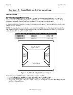
7.
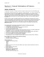
Insert the
Back Box
into the wall and carefully hold it evenly in place as to not allow it to fall into the wall.
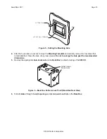
8.
Insert each
Mounting Clip
into
Slot A
while positioning the
“T”
shape of the
Mounting Clip
on the
inside
surface
of the
Back Box
as shown in
Detail A
of
Figure 7
.
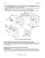
9.
Push the
clip
with your thumb in the direction of the
arrow
. The
back
of the
clip
should move down into
Slot B
.
NOTE:
If more pressure is needed, use a screw driver as shown in
Detail B
of
Figure 7.
10.
Repeat
Steps 8-9
for all
four clips
. A
rear view
of the
Back Box
with
clips installed
is shown below.
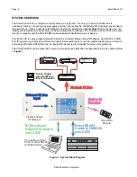
Figure 7 – Installing Back Box Mounting Clips
SPLCD POWER SUPPLY AND INPUT/OUTPUT WIRING INSTRUCTIONS
The SmartPad LCD can be interfaced in numerous fashions; Standard Xantech IR Bus, RS232, Direct Connect
to MRC88, External IR Input, and Local IR (Emitter Output). The following sections address each of these
wiring configurations.
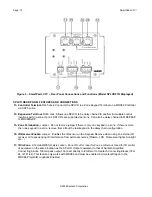
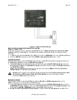
POWER SUPPLY & STANDARD XANTECH IR OUTPUT BUS WIRING
(Figure 3- Item 18)
A 4-terminal WECO connector is provided with the SPLCD for the +16VDC, GND, STATUS, and IR OUT
connections. For convenience of wiring, it is recommended that the Power Supply and IR Connecting Block be
installed at the same location, typically the system head-end, although this is not required. If installed at the


