LG 42PC5D Series, Service Manual
The LG 42PC5D Series is a high-quality television that provides a stunning visual experience. To ensure a seamless user experience, we offer a free Owner's Manual for download on our website. Explore the functionalities and settings of your LG 42PC5D Series with our comprehensive manual available for download at manualshive.com.
Share
Download


Reviews:
No comments
Related manuals for 42PC5D Series
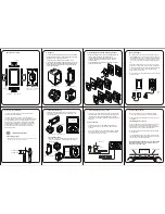
XTouch Series: XTouch50
Brand: Xilica Audio Design Pages: 2

n TPMC-12
Brand: Crestron Pages: 70

MAPPC900-ENG
Brand: B&R Industries Pages: 306

DGTCHKSK43
Brand: Displays2go Pages: 24

TLP 700TV
Brand: Extron electronics Pages: 4

KPC-1760
Brand: Quanmax Pages: 38

PDX2-057T-5A
Brand: Icop Pages: 29

7150
Brand: Samsung Pages: 65

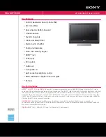
KDL-26M4000/W - Bravia M Series Lcd Television
Brand: Sony Pages: 2

KDL-26ML130 - 26" Bravia M-series Digital Lcd Television
Brand: Sony Pages: 2

KDL-26M4000/T - Bravia M Series Lcd Television
Brand: Sony Pages: 2

KDL-26M4000/R - Bravia M Series Lcd Television
Brand: Sony Pages: 2

KDL-26M4000/R - Bravia M Series Lcd Television
Brand: Sony Pages: 2

KDL-26N4000 - 26" LCD TV
Brand: Sony Pages: 6
KDL-26M3000 - 26" Bravia M-series Digital Lcd Television
Brand: Sony Pages: 2

KDL-22BX300 - Bravia Bx Series Lcd Television
Brand: Sony Pages: 2

KDL-19M4000/S - Bravia M Series Lcd Television
Brand: Sony Pages: 2

KDL-19M4000/P - Bravia M Series Lcd Television
Brand: Sony Pages: 2


