


Page: 80
SmartPad LCD
™
© 2008 Xantech Corporation
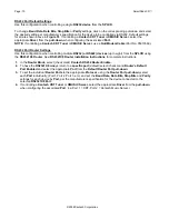
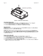
VIDEO BRACKET SUB-ASSEMBLY
MOUNTED ON LEFT SIDE (1ST OPTION)
VIDEO OUT
VIDEO IN
Figure 61 – Video Bracket Sub-Assembly
Video Bracket Sub-Assembly
1.
Attach the
Video Bracket Sub-Assembly
to the
SPLCD64V Rear Panel
as shown in
Figure 61
.
2.
Connect the
Video IN Harness
to the
Video IN
and
GND Video Terminals
.
3.
Connect the
Video OUT Harness
to the
Video OUT
and
GND Video Terminals
.
Video Connections
VIDEO IN:
Connect the zone
composite
video signal to the
Video IN
BNC Connector
on the
Video Bracket
Sub-Assembly
, attached to the
SPLCD64V Rear Panel
.
VIDEO OUT:
A buffered composite video signal can also be run
out
of the panel to a main
Video Monitor
in
the zone if desired. To do this, connect a
RG-6 quad-shield coaxial
or other
shielded video cable
, terminated
with a
BNC Connector
, to the
Video Out BNC Connector
on the
Video Bracket Sub-Assembly
, attached to
the
SPLCD64V Rear Panel
.
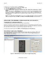
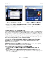
Picture-In-Picture Mode (PiP)
A PiP window can be placed on any
Page
except
the
Home Page
. To enable a PiP:
1.
In the
SPLCD System Window
,
navigate
to the
Page
on which the
PiP
is to be placed.
2.
In the
virtual SPLCD
, right click on a
blank space
(no GTL) and select
Enable PiP
from the
pop-up
.
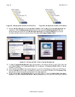
3.
Click & Drag the
PiP
to the desired location on the
GTL Page
.
4.
To
resize
the
PiP
, click on the
PiP
. In
Button Attributes
click the
’+’
next to
Size
. Double click
Width
and
Height
to change the values to resize the
PiP
.


