


SmartPad LCD
™
Page:
17
© 2008 Xantech Corporation
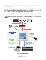
head-end, run
4-conductor 18AWG stranded, non-shielded wire
to the SPLCD. If multiple SPLCD’s are
being installed pull home-runs from each SPLCD location back to the head-end.
Power Supply Wiring
All models of
SPLCD
require a
16VDC Power Supply
.
•
Xantech
Model#
SPLCDPS1
is a 16VDC Power Supply @ 1.5A that can power for
one
SPLCD
.
•
Xantech
Model#
SPLCDPS4
is a 16V DC Power Supply @ 3.12A that can power up to
four
SPLCD’s
.
Power Supply With a Connecting Block
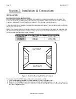
1.
Connect the
2.1mm coaxial plug
of the
power supply
into the
16V DC Input
of the
SPLCD Connecting
Block
(Model#
SPLCDCB100
).
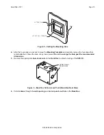
Power Supply Hard Wired to the SPLCD
1.
Cut the
2.1mm coaxial plug
off the end of the
power supply wire
. Spread the two leads and strip
approximately ¼” off the end of each lead.
2.
Using the included 4-terminal WECO connector, connect the
white stripe lead
to the
+16V In Only
Terminal
and the
black wire
to
GND
.
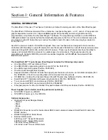
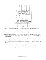
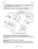
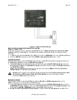
IR Wiring
Connect
4-conductor 18AWG stranded non-shielded wire
from the
IR BUS, GND, STATUS
(optional) and
+16VDC Terminals
on the
SPLCD
to the appropriate
terminals
on the
SPLCDCB100 Connecting Block
.
(
Figure 8
)
Figure 8 – Power Supply and IR Output Wiring (Model # SPLCDCB100 Shown)
Caution:
The
STATUS
Terminal
can be either an
INPUT
(5-30VDC from remote device) to
trigger
a
Macro
within the
SPLCD
or
illuminate
the
Talkback/Status LED
as indication of a unit or zone’s power
status, or it can be an
OUTPUT
(+12VDC from the SPLCD) to
activate
an
external device
. This is


