


SmartPad LCD
™
Page:
19
© 2008 Xantech Corporation
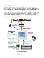
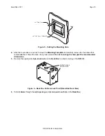
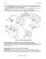
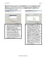
Figure 9 – External IR Input Wiring
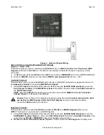
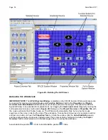
MRC CONTROLLER AND EXPANSION PORT WIRING
(Figure 3 – Items 13/14)
These RJ45 ports are used for interfacing the
SPLCD
directly to a
MRC Controller
and/or
Expansion MRC
Keypads
, (SLPCD’s or MRC88KP’s). The SPLCD can interface to the MRC Products in two ways via this
connection:
1.
Via
IR
along the dedicated
IR lines
of the
CAT5
connected to a
MRC44/88
(Pins 4 & 5) (MRC88 & MRC44)
2.
Direct to a
MRC88
processor via the internal
RS485 communication lines
(Pins 1, 2 &7)
.
Controller Terminal
This terminal is used to connect the
SPLCD
either directly to a MRC88 Controller Zone Keypad Terminal or to
the
Expansion Terminal
on an existing
MRC88 Zone Keypad
.
1.
Using
CAT5 cable
terminated at both ends with RJ45 connectors,
(EIA/TIA 568B standard)
connect the
Zone Keypad Terminal
on the
MRC88 Rear Panel
to the RJ45 connector marked
Controller Terminal
on
the
SPLCD Rear Panel
.
NOTE:
When the
SPLCD
is the
last keypad
connected in line with the
MRC88
, the
Zone Termination
Jumper
(
Figure 3 – 15)
needs to be installed.
Caution:
Power voltage for the keypad is transmitted along this cable!
Incorrect wiring on this cable
can destroy the MRC Keypad and/or the SPLCD Display!
Be sure to test cable for proper
connections
before
making connections.
Expansion Terminal
This terminal is used to connect the
SPLCD
to additional
SPLCD’s
or
MRC88 Keypads
within a zone.
NOTE:
This feature is only functional in a MRC88 System.
1.
Using
CAT5 cable
terminated at both ends with RJ45 connectors,
(EIA/TIA 568B standard)
connect the
EXPANSION Terminal
(
Figure 3 – 14)
on the
SPLCD Rear Panel
to the RJ45
Controller Terminal
on the
rear of the next
SPLCD
or
MRC88KP
in line. (Four keypads max per zone.)
2. Remove
the
Zone Termination Jumper
(
Figure 3 – 15)
from all
but the
last keypad
in the daisy chain.


