


Page: 52
SmartPad LCD
™
© 2008 Xantech Corporation
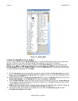
TESTING RS232 COMMAND STRINGS
There are two methods of testing RS232 Command Strings directly from the Palette Editor: One is directly out
of the PC’s Com Port and the second method is through the SPLCD’s RS232
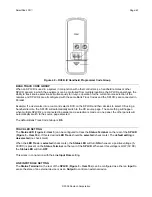
Serial Port (Figure 3 Item 20)
.
Using either method, you can control the component or device directly for confirmation of the command string
programming or send the command to an RS232 Utility Program to verify proper output (this is good for
troubleshooting purposes or for testing the command without the component or device present).
Using PC Test
1.
Connect the
Com Port
of the
PC
running
Universal Dragon
to the corresponding component or device of
the commands to be tested.
NOTE:
A
Null Modem cable
may be necessary for communicating with the Component or Device. Check
the manufacturer’s specification to see if this is required.
2.
In the
Palette Editor
click
Test.
It will highlight
dark blue
.
3.
In the
Palette Editor Tool Bar
, click
RS232 Settings
(
) to be sure the
RS232 Port Settings
are
properly set appropriate for the connected device. (Refer to the mfg’s Instruction Manual of the component
or device being tested for the proper communication settings.)
4.
In
Palette Editor
, select the appropriate
Brand/Component
and then select
RS232
from the
Component
sub-directory
.
5.
In the
Function List
, click on the
command string
to be tested.
NOTE:
Only commands with the
icon will be able to be tested.
6.
The connected component or device should respond appropriately for the command sent. If not, check the
command string
entered and
port settings
in the
RS232 Settings Window
. If device still doesn’t
respond, see the
Troubleshooting Section
to verify RS232 communication.
7.
Repeat
Steps 1-6
for all
RS232 Commands
prior to programming the
SPLCD
.
Using SPLCD Test
NOTE: The PC running Universal Dragon needs to connected to the Programming Port of the SPLCD
and communication verified (Base Unit “Who Am I”) before continuing.
1.
Connect the
Serial Port
on the
SPLCD Rear Panel
(Figure 3 Item 20)
to a Xantech
RS232422 Converter
(not included). Connect the
RS232 Port
on the
RS232422
to the appropriate port on the component or
device of the commands to be tested.
NOTE:
A
Null Modem cable
may be necessary for communicating with the Component or Device. Check
the manufacturer’s specification to see if this is required.
2.
In the
Palette Editor
click
Test.
It will highlight
dark blue
.
3.
In the
Palette Editor Tool Bar
, click
RS232 Settings
(
) to be sure the
RS232 Port Settings
are
properly set appropriate for the connected device. (Refer to the mfg’s Instruction Manual of the component
or device being tested for the proper communication settings.)
4.
In
Palette Editor
, select the appropriate
Brand/Component
and then select
RS232
from the
Component
sub-directory
.
5.
In the
Function List
, click on the
command string
to be tested.
NOTE:
Only commands with the
icon will be able to be tested.
6.
The connected component or device should respond appropriately for the command sent. If not, check the
command string
entered and
port settings
in the
RS232 Settings Window
. If device still doesn’t
respond, see the
Troubleshooting Section
to verify RS232 communication.
7.
Repeat
Steps 1-6
for all
RS232 Commands
prior to programming the
SPLCD
.
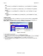
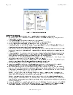
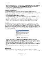
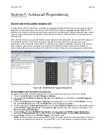
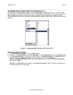
RS232 COMMAND GROUPS
Unlike previous versions of Dragon Drop-IR, it is not necessary to create RS232 Command Palettes from
programmed commands. Universal Dragon does this automatically. Programmed RS232 Commands are
placed into
Command Groups
that can be accessed by clicking
Show IR Library
in the
Palette Editor
. The
Command Groups will appear in the
Brand/Component List
just as the IR and Hex Command Palettes do.
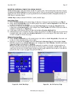
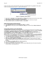
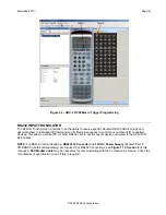
The programmed commands will be listed as
RS232
in the
Code Type sub-directory
, and programmed
commands will be included in the same
Group
as RS232 Commands from the Library. RS232 Commands are
indicated by the
RS232 Command Symbol
next to each
Function
in the
Function List
.


