background image

SmartPad LCD


Page: 

47 


© 2008 Xantech Corporation 

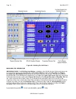
EDITING FUNCTION NAMES IN THE PALETTE EDITOR


If a function on the 

Source Remote

 is not displayed in the 

Function List

, you can either 

Rename

 an 

existing 

function

 or 

Add

 a 

new function

 to the 

List

. Editing 

Function Names

 in the 

Palette Editor

 will only affect the 

specific 

Brand/Component Palette File

 you are currently saving to. (i.e. Making a change to a function under 

DENON DVD will only appear in DENON DVD). 
 

To Rename an Existing Function 

1. 

Right-click on the 

function

 to be 

renamed

2. 

Select 

Rename

 from the 

pop-up

3. 

Edit the text as desired and press 

Enter

 on your keyboard. 

4. 

The 

Rename Window

 will appear with a 

Warning Message

. Click 

YES

 to 

Save


To Add a New Function 

1. 

Scroll down to the bottom of the 

Function List

 on the right side window of the 

Palette Editor

2. 

Right click on a 

blank area

 of the 

List

 and select 

New Command

 from the 

pop-up

3. 

Enter the 

name

 of the 

new function

 as you would like it to appear in the 

List

 and press 

Enter

 on your 

keyboard to 

Save


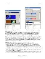
TESTING IR COMMANDS IN THE PALETTE EDITOR 

Before programming any SPLCD Buttons with learned commands, they should be tested to assure that the 
learned commands are the correct commands and that they are functional. The wrong command or a non-
functioning command in a power or source select sequence will cause system control errors. It is much easier 
to find these types of errors by testing newly learned commands, than to try to isolate the problem later. 

NOTE: 

To test learned commands, the 

PC

 running 

Universal Dragon

 must be connected to the 

SPLCD

 via 

the 

RS232

 or 

USB Programming Port.

 The 

IR output

 of the 

SPLCD

 should be connected to a 

Connecting 

Block

 as shown in 

Figure 8, Page 17

. Connect an 

IR Emitter

 to the connecting block and attach it to the 

component being tested, over the 

IR Eye

.  

1. 

With the 

PC

 connected to the 

SPLCD Programming Port

, select

 Test

 in the

 Palette Editor Window

. The 

TEST Button

 should now be highlighted. 

2. 

Click on each of the command names one-by-one that need to be tested. The SPLCD screen will display a 
test screen for a second or two. 

3. 

The controlled component should respond to each command sent. (i.e. “Power” turns the source ON or 
OFF, “PLAY” plays the content etc.) 

NOTE:

 Only functions with a 

XIR1

 (

) or 

XIR2 Symbol

 (

 ) will execute. 

IR Commands

 from the 

IR 

Library

 will not appear in 

Edit 

Test Mode

. To test 

IR Commands

 from the 

IR Library

, change the 

Palette 

Editor Mode

 to 

Palette

4. 

If a component does not respond to a command, re-learn and re-test the IR command until the component 
responds. 

5. 

Repeat 

Steps 1-6

 for all commands to be tested. 


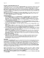
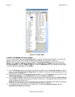
IR COMMAND GROUPS 

Unlike previous versions of Dragon Drop-IR, it is not necessary to create IR Palettes from learned commands. 
Universal Dragon does this automatically. Learned IR Commands are placed into 

Command Groups

 that can 

be accessed by clicking 

Show IR Library

 in the 

Palette Editor

. The 

Learned Commands

 will appear in the 

Brand/Component List

 just as the 

Library Commands

 do. The 

Learned Commands

 will be listed 

numerically

 in the 

sub-directory

, but will 

not

 have an associated 

numeric code group suffix

 in parenthesis. 

(

Figure 30

Learned Commands

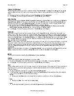
 can also be differentiated from 

Library Commands

 by the 

IR Code Symbol


next to each 

Function

. An 

IR Library Command

 will have a 


Symbol 

and a 

Learned IR Command

 will 

have a 

XIR1


 or 

XIR2 

 Symbol

 just to the left of the 

Function Name

 in the 

Function List

NOTE:

 The XIR1 Symbol features a red ‘1’ and the XIR2 Symbol features a red ‘2’. 


Summary of Contents for SPLCD64G

Page 1: ...INSTALLATION PROGRAMMING MANUAL SMARTPAD LCD TOUCH SCREEN PANEL CONTROLLER Models SPLCD39G SPLCD64G SPLCD64V SPLCD39G SPLCD64V ...

Page 2: ...on For example the appliance should not be situated on a bed sofa rug or similar surface that may block the ventilation openings or placed in a built in installation such as a bookcase or cabinet that may impede the flow of air through the ventilation openings 9 Heat The appliance should be situated away from heat sources such as radiators heat registers stoves or other appliances including amplif...

Page 3: ...Controller Terminal 19 Expansion Terminal 19 Serial RS422 232 Port Wiring 20 IR In Zone 21 Installing THE SPLCD INto THE Back Box 22 Viewing Angle 22 SECTION 3 MAINTENANCE CALIBRATION 23 CALIBRATION 23 TOUCH SENSE CALIBRATION 23 MAINTENANCE 23 Cleaning 23 SECTION 4 PROGRAMMING THE SMARTPAD LCD 24 INSTALLING AND CONFIGURING THE UNIVERSAL DRAGON SOFTWARE 24 UNIVERSAL DRAGON MINIMUM REQUIREMENTS 24 I...

Page 4: ...OR A SINGLE SOURCE 41 Insert a New Page 41 Return to Previous Page 41 IMPORTING AND EXPORTING SPLCD PAGES 42 Exporting SPLCD Pages 42 Importing SPLCD Pages 42 LEARNING IR COMMANDS CREATING PALETTE FILES 43 Built In IR Code Library 43 TESTING IR COMMANDS IN THE IR LIBRARY 44 IMPORTING XANTECH LEGACY IR PALETTE FILES 45 Learning IR Commands XIR2 45 Finding the Optimal Positioning of the Teaching Rem...

Page 5: ...8 Triggered Sequences 59 Teaching RC68 Trigger Commands to a Universal Remote 60 Programming the URC 2B P for Use With SPLCD RC68 Triggered Sequences 60 RS232 INPUT TRANSLATOR 61 Programming IR Commands and Sequences 62 Selecting IR Command Groups from the IR Code Library 62 Associating RS232 Commands with IR Commands 62 Testing Commands in the RS2322 Input Translator 63 SENSE TRIGGER MACROS 63 Pr...

Page 6: ...r 75 Creating Transparent GTL s over a Volume Bar 75 Assigning the Proper RC68 IR Codes to the Transparent GTL s 76 Programming SPLCD for use with MRC44 Zone Control 77 SPLCD 64V VIDEO CONNECTIONS PROGRAMMING 79 Checking Firmware Version 79 Video Bracket Sub Assembly 80 Video Connections 80 Picture In Picture Mode PiP 80 Enabling Full Screen Video Mode 81 Return to PiP Mode 81 TRANSPARENT BUTTON O...

Page 7: ...h Xantech s MRC88 products for seamless integration with the Whole house Audio Video Entertainment system The SmartPad LCD Touch Screen Panel Keypad includes the following components One SmartPad LCD Touch Screen Panel One DB9 RS232 programming cable to connect Part No 05913778 One USB programming cable Part No 05913660 One front panel designer Bezel white Keypad Installation Kit which includes th...

Page 8: ...ia a RS232 or USB Port Programming cables and software included Universal Dragon is used to graphically design your screens and assign IR and or RS232 Macros An internal IR Library is also included for ease of programming The SmartPad LCD can be wired into numerous simultaneous application configurations such as outlined below in Figure 1 VCR Satellite Receiver AV Receiver Xantech IR Bus IR Connec...

Page 9: ...alk Back Status LED LED indicates presence of IR and or programmable STATUS indication of Zone or other user defined power on off indicator RC68 IR Trigger Sequencer Trigger IR and or RS232 Macros via RC68 IR command received at the built in IR Receiver Status Input Trigger IR and or RS232 Macros with a voltage between 5 30V DC 100mA Status Output Send an output voltage to trigger the on off state...

Page 10: ...ARTPAD LCD PANEL AND FEATURE DESCRIPTIONS 12 4 2 6 5 7 8 10 9 11 1 3 Figure 2a SmartPad LCD Model SPLCD39G Front Panel Features and Functions 5 6 3 2 4 12 9 8 7 10 11 1 Figure 2b SmartPad LCD Model SPLCD64G SPLCD64V Front Panel Features and Functions ...

Page 11: ...ensitivity if positioned as shown in Figures 2a 2b Lower Viewing Angle with the IR Receiver positioned on the left side or counterclockwise if installed in the reverse position Upper Viewing Angle with the IR Receiver positioned on the right side 5 IR Learning Eye The IR Learning Eye allows teaching IR Codes to Universal Dragon via the SPLCD when connected to a PC Com Port Serial or USB 6 IR Learn...

Page 12: ...one keypad in a zone If there is more then one keypad in a zone remove from all but the last keypad in the daisy chain configuration 16 IR Receiver Enable Jumper Enables the IR sensor on the Keypad Remove when using an external IR receiver or if experiencing IR interference from external sources Plasma LCD Fluorescent lights Sunlight etc 17 IR In Zone 2 Terminal WECO style socket Zone IR out for l...

Page 13: ...89 44 791 44 CB60 etc Can drive a single emitter up to 2000 on 18AWG 19 External IR Input 4 Terminal WECO style socket Allows connection of other Xantech IR Receivers and or Keypads to be used in conjunction with the SPLCD RC68 commands received here can trigger internal IR and or RS232 Macros to be output on the IR BUS Terminal and or Serial RJ45 Terminal 20 SERIAL Bi directional RS422 Serial Por...

Page 14: ... a 0 00 inch tolerance for this cutout It is imperative that the provided mounting template be used to assure proper hole size Check the table below to be sure you are using the proper Mounting Wall Cutout Template SPLCD Model Mounting Template Part No Cutout Dimensions SPLCD39G 08187158 5 50 X 6 50 SPLCD64G 08187157 7 63 X 9 49 SPLCD64V 08187157 7 63 X 9 49 CUT OUT CUT OUT CUT OUT CUT OUT Figure ...

Page 15: ...ully remove the four areas that remain attached Clean the area of any loose pieces Do not to enlarge the hole past the recommended dimensions 5 Remove the appropriate hole knockouts on the Back Box to allow for wiring of the SPLCD Cable Access Punch Outs Figure 6 Back Box Cable Access Point Back Box Rear View 6 Pull all cables through the wall opening and desired punch out hole in the Back Box ...

Page 16: ... rear view of the Back Box with clips installed is shown below Figure 7 Installing Back Box Mounting Clips SPLCD POWER SUPPLY AND INPUT OUTPUT WIRING INSTRUCTIONS The SmartPad LCD can be interfaced in numerous fashions Standard Xantech IR Bus RS232 Direct Connect to MRC88 External IR Input and Local IR Emitter Output The following sections address each of these wiring configurations POWER SUPPLY S...

Page 17: ...red to the SPLCD 1 Cut the 2 1mm coaxial plug off the end of the power supply wire Spread the two leads and strip approximately off the end of each lead 2 Using the included 4 terminal WECO connector connect the white stripe lead to the 16V In Only Terminal and the black wire to GND IR Wiring Connect 4 conductor 18AWG stranded non shielded wire from the IR BUS GND STATUS optional and 16VDC Termina...

Page 18: ... unit from the 16VDC supply voltage Use this output to power the external IR Receiver The 12VDC output can power a load of up to 100mA maximum 80mA effective load Caution This is a 12VDC OUTPUT only Do not connect a 12V power source to this point This is only an OUTPUT to power an external IR Receiver GND Both GND Terminals are internally connected to the same point and represent chassis ground of...

Page 19: ... the Zone Keypad Terminal on the MRC88 Rear Panel to the RJ45 connector marked Controller Terminal on the SPLCD Rear Panel NOTE When the SPLCD is the last keypad connected in line with the MRC88 the Zone Termination Jumper Figure 3 15 needs to be installed Caution Power voltage for the keypad is transmitted along this cable Incorrect wiring on this cable can destroy the MRC Keypad and or the SPLCD...

Page 20: ... Serial Port on the SPLCD Rear Panel to the Serial Port on a Xantech RS422232 Figure 10 NOTE 1 The RS422232 Converter sold separately and a 12VDC Power Supply Xantech model 781ERGPS should be located within 30ft of the RS232 device to be controlled NOTE 2 A Null Modem Adaptor may be necessary for proper communication Please consult manufacturer s specification of device being controlled DB9 Pin Ou...

Page 21: ...he SPLCD Rear Panel to the white stripe wire on the emitter wire and connect the GND Terminal to the black wire on the emitter cable using the included 2 conductor screw type Removable Connector 3 To control multiple components in the same area connect these same terminals to an Amplified Connecting Block Xantech Model 791 44 using 18 20AWG 2 conductor cable NOTE IR In Zone is a MRC88 feature and ...

Page 22: ...ck Box leaving slack for strain relief and connection to appropriate terminals on the SPLCD Rear Panel 2 Insert the SPLCD into the Back Box oriented according to desired viewing angle so that the unit is flush within the Back Box 3 Secure with four 6 32x screws Part No 103497 NOTE Do not completely tighten screws 4 Make sure the SPLCD is level within the box and finish tightening screws Be sure no...

Page 23: ...ears 5 Release the screen The black dot should appear on the same side as the built in IR Receiver 6 With the stylus touch the center of the dot and release 7 Another calibration dot will appear towards the top middle of the screen Again touch the center of the dot and release One more calibration dot will appear Repeat as above There a total of three calibration points After touching the third ca...

Page 24: ...ORT on your PC USB Programming Part No 05913660 Connects the SPLCD USB Programming Port Figures 2a 2b Item 9 to the PC s USB port CONNECTING THE SMARTPAD LCD TO THE PC To program the SmartPad LCD the unit must be connected to a PC running Universal Dragon Drop IR Programming Software DB9 Serial Connection 1 Connect the supplied DB9 Programming Cable Part No 03972440 to your PC Serial Port and the ...

Page 25: ...al Dragon Drop IR onto your hard drive as follows 1 Insert the disc into your computer s CD ROM drive If your drive has been set for auto run a Xantech Welcome Menu will appear If not access your CD ROM with Windows Explorer and double click the file setup exe 2 On the Welcome menu click NEXT 3 Follow the on screen instructions as the program installs Installation time will vary depending on the s...

Page 26: ...firm the firmware version of the SPLCD This will serve two purposes One it will confirm the connection between the PC and the SPLCD that will be required for all programming and two it will assure that the SPLCD is up to date with all of the latest features and fixes Figure 14 Who Am I SPLCD Figure 15 Firmware Page Link 1 Connect the included DB9 Programming Cable Xantech P N 05913778 to a Serial ...

Page 27: ...the SPLCD SmartPad LCD Current Firmware Version Box The most recent SPLCD firmware update file will be featured here Click the link to download the most current Firmware Update For older versions click on Archived Firmware Versions and scroll to the desired version entries are sorted with the newest entries at the top of the list and the oldest at the bottom Click on the desired filename link to b...

Page 28: ... Serial Port is connected from the PC to the SPLCD 2 Set Universal Dragon up for a firmware upgrade Step 2 above 3 Before you double click the firmware file in Universal Dragon Step 3 above press and release the Reset Button on the SPLCD 4 Within 5 seconds of pressing the Reset Button double click the firmware file in Universal Dragon Step 3 above 5 The download should begin 6 If the download does...

Page 29: ... keypad and all tabs are visible Figure 19 6 If not selected click the Graphics Palette and Properties Tabs 7 Proceed to Section Creating the Graphical User Interface Default Project MRC88 To open pre configured a SPLCD Project Template for use with an existing MRC88 System click Default Project in Step 4 above Each SPLCD Model features an eight source layout that has been configured for use with ...

Page 30: ...utton for AutoBuild Wizard Click OK Proceed as follows 4 The AutoBuild Wizard Start Up Screen will appear Click Next 5 The Manufacturer Brand Select Window will appear Select the Brand for the device being added to the SPLCD Project from the pull down Click Next 6 The Device Select Window will appear Select the Device DVD Receiver etc for the device being added to the SPLCD Project from the pull d...

Page 31: ...pear and setup is complete for this device If the device does not respond select another Command Group and repeat Test until a good Group is found If no Group works click the None of the Codes Box Click Next 9 The Learning Window will appear IR HEX IR and RS232 Commands can be learned in this window To learn an IR Command in Command Type select Learned IR Select the command in the list click Learn...

Page 32: ...functions that are not required functions that need to be added or additional programming that is required Macro Sequences Trigger Commands etc see the Table of Contents in this Manual for reference to the sections that will guide you through those steps If you are satisfied with the results of the AutoBuild Wizard as is proceed to Sections Testing Commands Placed on the Virtual SPLCD and Transfer...

Page 33: ... easily create stylish and intuitive screens in multiple pages for controlling any IR and or RS232 Device Once a project is created and a setup environment chosen you are automatically placed in Graphics mode and are now ready to create your GUI Graphical User Interface screen Figure 19 SPLCD Graphic Page Edit Screen Populated ...

Page 34: ...nally making the button placement process much easier Figure 20 Rolling over the Project Overview or Properties Tab with the mouse will cause the Window to pop up The Window will automatically hide by moving the mouse anywhere on the screen clearing the view of the workspace To keep the window open for example to add or edit text on a button roll over the Properties Tab to un hide the window click...

Page 35: ...ures as Custom Backgrounds and Transparent Button Overlay Features Programming for additional information Page 83 Backgrounds Any Background from any Style can be used on a New SPLCD Project To choose a style 1 Select the Graphics Tab in the SPLCD System Window The Graphics Window should now be displayed in the work environment Selecting the Graphics Tab will also open the Graphics Palette 2 In th...

Page 36: ... on the Grid the GTL can be placed anywhere on the screen To move the GTL either click and drag to the proper placement or simply select the GTL with the mouse and then use the arrow keys on the PC Keyboard to move the GTL to the proper placement NOTE GTL X Y Coordinates are displayed in the Information Bar at the bottom of the Universal Dragon Screen The Snap to Grid will align same size same sha...

Page 37: ...roup of buttons This is useful for Volume and Channel Up Down controls See Section Creating Labels for additional information 5 Repeat Steps 3 4 for all desired Function Buttons for each Source EDITING GTL PROPERTIES The Properties of a GTL button can be edited for Text Font and Color This allows dragging a blank GTL Button onto the any page and editing it as needed This is useful when a button is...

Page 38: ...tons are already named but can be re named not recommended and blank buttons can be named for reference This setting does not change the appearance of the Button It only changes the Button Name in the Attributes 1 Double click to activate the text field 2 Enter the Button Name i e Page UP 3 Click Apply To make changes permanent in the File Menu select Save Size This setting allows modifying the si...

Page 39: ...ragon will associate the commands titled Play and Stop with those buttons NOTE 1 When adding or modifying Keywords be specific If a button is to be a Volume UP button be sure the Keywords include Volume Up and not just Up Same with Menu Up This will allow Universal Dragon to fine tune the search process and better associate the proper commands A quick review of the Function Lists within the Comman...

Page 40: ...e on the GUI screen to provide a description to a GTL or a group of GTL s i e Volume UP DOWN NOTE A Label is not programmable for any function A Button Text Only has the same capabilities as a Function GTL and a Source Text Only has the same capabilities as a Source GTL Figure 24 Insert Label To insert a Label proceed as follows 1 Right click on any blank area no GTL s in the SPLCD System Window 2...

Page 41: ...ured i e Page Down 4 A new page is now inserted and may be filled with additional Function Button GTL s 5 Additional pages can be inserted in the same manner as needed If no additional pages are required for the selected source place another blank Function Button GTL on the current page This button will be used to return navigate to the previous page Return to Previous Page 6 Drag a Function Butto...

Page 42: ...r called Pages within the Projects Folder C Program Files Xantech Universal Dragon Projects is convenient for keeping Pages and Projects in one place Click Save Importing SPLCD Pages 1 In the SPLCD System Window navigate to where a Page is to be Imported i e a Source Page with no Function Buttons 2 Right click in any blank space no GTL or PiP and select Import Page in the pop up 3 The Open Window ...

Page 43: ...in IR Code Library The IR Code Library is a large database of manufacturer s IR Commands for a whole assortment of brands and components If your manufacturer s codes are in our database there might not be any need to teach IR commands into the system To check the Universal Dragon s extensive IR Code Library do the following 1 Open a SPLCD Project 2 If not already open in the View Menu select Palet...

Page 44: ...c manufacturer component list of Command Groups as outlined above click on the first Command Group listed i e 1 32 A list of all of commands associated with this component will be displayed 2 With the PC connected to the SPLCD Programming Port select the Test Button located at the top of the Palette Editor Window The Test Button should now be highlighted in dark blue 3 Click the Power ON OFF comma...

Page 45: ...lick the Command Group The IR Commands will be listed in the right side window in the Palette Editor and are ready for button programming LEARNING IR COMMANDS XIR2 An IR Learning Eye is located on the front panel of the SPLCD and is accessible when the Bezel is removed Figures 2a 2b Item 5 NOTE Commands learned through the SPLCD s front panel learning eye XIR2 method are NOT backwards compatible t...

Page 46: ...ed NOTE Before performing Step 9 read Steps 9 12 as the RECORD process is a timed function You will have 5 seconds to perform the process before the system times out 9 Place the Teaching source remote in the optimal position as found above 10 Select the command to be learned in the Function List i e Power Play Stop etc The Learn IR Window will appear You will have approximately 5 seconds to learn ...

Page 47: ...CD should be connected to a Connecting Block as shown in Figure 8 Page 17 Connect an IR Emitter to the connecting block and attach it to the component being tested over the IR Eye 1 With the PC connected to the SPLCD Programming Port select Test in the Palette Editor Window The TEST Button should now be highlighted 2 Click on each of the command names one by one that need to be tested The SPLCD sc...

Page 48: ... least one Component and one Function have been programmed To find a New Brand that does not have any commands programmed in Palette Editor change Mode to Edit and scroll the list to the New Brand Adding Components and Functions 1 If not already selected in the Palette Editor click Mode and select Edit 2 In the Brands List select the Brand to which the New Component is to be added 3 Click the Add ...

Page 49: ...Program Files Xantech Universal Dragon vX X Palettes Click Save 8 In Universal Dragon in the Palette Editor click the Import Icon The Open Window will appear 9 Navigate to where the Command Group File was saved in Step 7 Using the Files of Type pull down select Legacy Palette Files pal rsl The saved file and all other rsl files should appear 10 Click the File to be imported The Import Palette Wind...

Page 50: ...ste from the pop up or press CNTRL V on your keyboard to paste the code to the window Click OK 14 A will now be displayed to the left of the function indicating the code has been successfully imported 15 Repeat Steps 8 13 for all commands to be imported from Remote Central Figure 36 Record Hex Data Figure 37 Pasted Hex Data ENTERING RS232 COMMANDS Creating RS232 Command Palette Files The SPLCD can...

Page 51: ...programmed with an RS232 Command i e Power Play Stop etc and select Record from the pop up The RS232 Command String Editor Window will appear The window will indicate the selected command in the Title Bar to assist in programming the proper command string to the proper function 5 Click in the ASCII or HEX row depending upon the type of data to be entered The selected row will change to dark blue 6...

Page 52: ...Programming Port of the SPLCD and communication verified Base Unit Who Am I before continuing 1 Connect the Serial Port on the SPLCD Rear Panel Figure 3 Item 20 to a Xantech RS232422 Converter not included Connect the RS232 Port on the RS232422 to the appropriate port on the component or device of the commands to be tested NOTE A Null Modem cable may be necessary for communicating with the Compone...

Page 53: ...Sequence NOTE At this point the SPLCD Source and Function GTL s should already be configured on the Virtual SPLCD in the SPLCD System Window If this has not been done return to Section Creating the Graphical User Interface GUI With the SPLCD Project open resize and configure the windows as shown in Figure 40 NOTE In the SPLCD System Window click the Macros Tab This will open the Command List Windo...

Page 54: ...d Play and Stop with those buttons To Auto Fill an SPLCD Page 1 Open a Source Page that has been configured with all required Source and Function GTL s 2 In the Palette Editor Window select the appropriate Brand and Component from the IR Library 3 Click and Drag the appropriate IR Command Group onto a blank space on the SPLCD Page in the System Window A Message Window indicating the number of IR C...

Page 55: ...command Timed Delays Timed Delays can be placed between commands in a Macro Sequence This is sometimes necessary in sequences when a delay is needed between two commands to allow a device to respond completely to the previous command i e After a POWER ON command is issued a delay is usually necessary before the next command will be recognized and should be added so the source components don t star...

Page 56: ...agon must be connected to the SPLCD via the RS232 or USB Programming Port The IR output of the SPLCD should be connected to a Connecting Block as shown in Figure 8 Page 17 Connect IR Emitters to the appropriate outputs on the connecting block and attach them over the IR eyes on the components being tested NOTE If RS232 Commands have been placed under any GTL s the SPLCD must be connected to the RS...

Page 57: ... select Save Project or in the Tool Bar click the Save Project Icon 2 The Save As Window will appear for a new unsaved project No window will appear when saving new work on a previously saved project 3 The default Folder for Universal Dragon Projects is C Program Files Xantech Universal Dragon vX X Projects Navigate to this location if the Projects Folder does not appear in the Save In Box 4 Enter...

Page 58: ...ding the project 3 At this point you should be able to do a Project Transfer from Universal Dragon to load your project into the SPLCD 4 If the download does not start check the PC s Port Settings to make sure the appropriate Port is selected 5 Please also note in an installed environment power fluctuations may also cause the Abort Project Load message to appear In this scenario don t abort projec...

Page 59: ...iggered in this fashion Figure 42 RC68 IR Code Triggered Sequencer PROGRAMMING RC68 TRIGGERED SEQUENCES Programming the RC68 Triggered Sequencers is similar to programming macros under GTL buttons 1 Click on the RC68 Tab in the SPLCD System Window 2 Open all the IR and RS232 Command Groups for the devices to be controlled in the RC68 Triggered sequence 3 Select the RC68 Sequence Trigger Command to...

Page 60: ...8 Trigger Command and locate the properly numbered RC68 Button on the RC68 Hand Held Programmer i e Button 80 4 Teach the RC68 Command to the Universal Remote per the remote s instructions 5 Repeat Steps 2 4 for all RC68 Trigger Commands to be used PROGRAMMING THE URC 2B P FOR USE WITH SPLCD RC68 TRIGGERED SEQUENCES Programming a Xantech Model URC 2B P Black or Platinum Universal Remote to trigger...

Page 61: ...rol any number of IR controlled devices This allows a central PC or other RS232 unit to control any IR device connected to the SPLCD IR Bus Output NOTE For RS232 Communication a RS422232 Converter and 12V DC Power Supply Xantech Part 781ERGPS both sold separately are required For RS232 Connections see Figure 11 in Section 2 of this manual A Null Modem cable may be necessary for communicating with ...

Page 62: ...sub directory of component types will open 4 In the Component sub directory click the appropriate Component Type i e VCR TV etc A sub directory of Command Groups will open 5 Select the proper Command Group Be sure to select an IR Command Group The RS232 Input Translator only outputs IR commands 6 Repeat Steps 3 5 for all components commands being used in the macro As multiple Command Groups are se...

Page 63: ...e so it is highlighted dark blue 2 In the System Window select an ASCII Command String with associated IR codes to be tested i e Command MC000 The command string should now be highlighted dark blue 3 The IR Commands listed under the Macro Command List for that selected ASCII Command should now be executed in order of appearance out of the IR Bus on the SPLCD Rear Panel 4 Verify that all components...

Page 64: ...nsing the power state of an external device to prevent unwanted power commands from being issued when not desired If the sensed device has a Status Output or a switched or sensed AC outlet with a DC Power Supply or 12V output when a Source GTL is pressed if the Status Line is Low Status 0V the Power ON Command will be initiated If the Status Line is High STATUS 5 to 30V DC the Power ON Command wil...

Page 65: ... Source selection Figure 47 Assigning Bank Track Codes to Source GTL s Programming Bank Track Codes 1 In the SPLCD System Window select the Macros Tab 2 Right click on a Source Button and select Properties or in the Palette Editor select the Properties Tab 3 In the Properties Window at the bottom of the window in the Button Attributes click Bank Track and select the appropriate Bank Track Code for...

Page 66: ...8 Code Group setting refers to the group of IR codes that will be used to trigger RC68 Sequences as discussed in Section 5 The number associated with this Code Group refers to the dial setting on the rear of a RC68 X Handheld Programmer Figure 49 The SPLCD Default Code Group is C9 This setting only needs to be changed if multiple SPLCD s are connected in parallel and have different control functio...

Page 67: ...ppen when multiple SPLCD s are connected in parallel and a selection is made on one panel the other panels will automatically switch to the source page selected The default Bank Track Code Group is D8 TRACK LED SETTING The Status LED Figure 2 Item 3 can be configured to track the Status Terminal on the rear of the SPLCD Figure 3 Item 19c If this is desired LED Track should be selected check mark T...

Page 68: ...an external device via a 12V trigger when an appropriately configured GTL is pressed i e Control a Projection Screen a Lift Drapes or an amplifier with a 12V DC Control Input Note The Status Output is rated at 15mA maximum BACKLIGHT SETTINGS This sets the LCD Backlight to stay ON for a specified amount of time after the display is last touched The Backlight can be set to stay ON from 1 30 seconds ...

Page 69: ...on the Project Options Icon and in the Options Window select the RS232 Tab This will display all of the configurable RS232 settings for the Serial Port Figure 51 NOTE The Serial Port on the SPLCD Rear Panel is a RS422 Port Use of this Port requires a Xantech RS422232 Converter or a RS2321X8 Router and a 781ERGPS Power Supply to communicate with RS232 controlled devices Figure 51 RS232 Port Default...

Page 70: ...iple RS232 or RS422 devices up to eight from the SPLCD using the RS2321X8 Router See RS2321X8 Router Installation Instructions for complete instructions 1 In the Router Block select check mark Xantech RS232 Router Enable 2 To have the RS2321X8 always return to a specific port default select check mark Router s Default Port Enabled and select the appropriate Port from the Default Router Port pull d...

Page 71: ...anel and the other end to the Controller Terminal on the SPLCD Rear Panel 2 Connect a 16V DC Power Xantech Part SPLCDPS1 directly to the IR Bus 16V DC and GND Terminals on the SPLCD Rear Panel NOTE The SPLCD cannot be powered directly from the MRC88 Controller 3 If using multiple keypads in a single zone the last keypad in line must have the Zone Termination Jumper installed NOTE SPLCD comes with ...

Page 72: ...ndow click the Internal Commands Tab 4 In the Internal Command Window select MRC88 Button Emulation from the pull down NOTE The MRC88 Internal Commands are pointers to button locations within the MRC88 Controller The SPLCD can now initiate whatever Macros are programmed within the MRC88 under these buttons 5 Scroll through the list and associate the SPLCD Button to the appropriate MRC88 Internal C...

Page 73: ...n a MRC88KP 10 If more button control is needed from the SPLCD additional Function Button GTL s can be placed and programmed with IR Commands to pass IR through the CAT5 to the MRC88 Controller as you would in a standard project for additional control functionality of external devices NOTE To trigger Macro Sequences setup RC68 IR Triggered Macros in the MRC88 Project By doing so the SPLCD only nee...

Page 74: ... values under Size The Status and Informational Displays cannot be resized MRC88 OBJECT PROGRAMMING ADDING VOLUME BAR STATUS BAR ETC TRANSPARENT GTL S AND MRC88 EMULATION Combining these two features allows for unique programming possibilities Below is an example for creating Interactive Volume Bars so the user can press different areas of the Volume Bar and have the Zone Volume Level jump immedia...

Page 75: ...the 48 Button and the discrete Set Volume Level 50 Command under the 10 Button on the Virtual RC68 SPLCD MRC88 PRESET VOLUME LEVEL PROGRAMMING The following Steps will be performed in the SPLCD Project for the system being configured Figure 56 Configuring MRC88 Volume Preset Triggers Placing the Volume Bar 1 Right click on a blank area of the Background no GTL or PiP and select Insert MRC88 Object...

Page 76: ...8 Palette and choose MRC88 from the Xantech Model drop down 3 Click the RC68 Remote Tab on the Virtual RC68 4 In the SPLCD System Window select the Transparent GTL placed on the lower 1 3 of the Volume Bar 5 Click the 80 Button on the Virtual RC68 In the Macro Command List Window you should see the command C A8 10 Xantech MRC88 6 Repeat Steps 4 5 with the RC68 48 Command associated with the middle...

Page 77: ... Place a Source GTL for OFF if desired Some Source GTL Style Groups have OFF Buttons already made Some will require adding a Caption in the Button Properties Attributes Window after the Blank Source GTL has been placed a With the OFF GTL selected on the RC68 Palette select OFF button 68 and verify the proper command is shown in the Macro Command List Window 12 On the Home Page place Function GTL s...

Page 78: ...OFF Source GTL will have the RC68 80 Command in the 48 Code Group placed under it as an IR Command that will be output to the MRC The RC68 80 Command in the 48 Code Group will be configured in the MRC as a RC68 Trigger so when the 80 Command is received by the MRC it will execute the Zone Toggle Power Command Figure 59 Figure 58 SPLCD MRC44 Zone Toggle Power Programming Figure 59 MRC44 Toggle Powe...

Page 79: ...gon Drop IR SPLCD Version 1 2 0 or higher but downloading Universal Dragon from www xantech com is highly recommended for programming this device Figure 60 Who Am I Window Checking Firmware Version To check the SPLCD64V for proper firmware version connect the PC running Universal Dragon to either the Com Port or USB Port on the SPLCD Front Panel using the appropriate included cable In the Menu Bar...

Page 80: ...d composite video signal can also be run out of the panel to a main Video Monitor in the zone if desired To do this connect a RG 6 quad shield coaxial or other shielded video cable terminated with a BNC Connector to the Video Out BNC Connector on the Video Bracket Sub Assembly attached to the SPLCD64V Rear Panel Picture In Picture Mode PiP A PiP window can be placed on any Page except the Home Pag...

Page 81: ...olume UP DOWN or Channel UP DOWN Buttons while maintaining functionality even when in Full Screen Video mode Placing Transparent Button GTL s in Full Screen Video Mode 1 Right click on the Pip Screen and select Navigate from the pop up NOTE A Full Page Screen will appear with a Transparent Button Object displayed in the middle This object is the Return To PiP Button and cannot be removed This butt...

Page 82: ...yboard to position the Button to the matching X Y values Repeat for Volume DOWN and any other Transparent GTL s as appropriate Some users may prefer to have the transparent Volume UP DOWN and Channel UP DOWN buttons in the four corners of the screen in Full Video Mode Transparent Button GTL and Music Server Integration To interface to a Music Server Video Menu Screen or any other product s Video M...

Page 83: ...trol system NOTE Scanned images and photographs can easily be converted to BMP or PNG Files using My Pictures on your PC by selecting an image and performing a Save As and selecting BMP or PNG as the file type Third Party software applications such as Adobe Photoshop can also be used The example below illustrates how Transparent GTL Buttons can be placed over areas of the Custom Background image o...

Page 84: ...s Over a Custom Background 5 To place a Transparent Button GTL right click anywhere on the blank not a GTL area of the screen and select Insert Object then Transparent Button from the pop up A Transparent Button GTL will appear outlined on the screen 6 Click and drag the button to the desired location i e over the Video Display A V Receiver DVD Player 7 Re size the Button to the shape of the devic...

Page 85: ...lation and Programming Manual SmartPad LCD 2008 Xantech Corporation Document 08901480 Rev C This document is copyright protected No part of this manual may be copied or reproduced in any form without prior written consent from Xantech Corporation Xantech Corporation shall not be liable for operational technical or editorial errors omissions made in this document ...

Reviews: