


Page: 18
SmartPad LCD
™
© 2008 Xantech Corporation
important to note before
STATUS
wiring is made between the
SPLCD
and the
other device
.
DO NOT
CONNECT AN OUTPUT TO ANOTHER DEVICE’S OUTPUT!
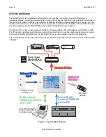
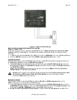
External IR Input Wiring
(Figure 3 – Item 19)
A 4-terminal WECO connector is provided for convenient wiring of external IR Receivers (780, 291, 480, 490
Series) to the SPLCD display. IR commands received here will be rebroadcast and passed out via the Xantech
IR Bus of the SPLCD (
Figure 3 – Item 18
). RC68 commands received here (of the proper Code Group, C9 set
as default) can trigger internal IR or RS232 Macros programmed into the SPLCD.
•
+12VDC Output:
This is a voltage reg12VDC output signal derived internal to the SPLCD unit from
the 16VDC supply voltage. Use this output to power the external IR Receiver. The 12VDC output can
power a load of up to 100mA maximum (80mA effective load).
Caution: This is a 12VDC OUTPUT only. Do not connect a 12V power source to this point. This is
only an OUTPUT to power an external IR Receiver.
•
GND:
Both
GND Terminals
are internally connected to the same point and represent chassis ground
of the
unit. Connect
either terminal
to the
GND
of the
external IR Receiver
.
•
IR Input:
Connect to the
IR Output
of an
IR Receiver
such as Xantech 780, 291, 480, 490 Series or other
compatible device.
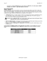
Pull
3-conductor 18-24AWG stranded non-shielded wire
(
4-Conductor
if using the
Status
line) from the
SPLCD
location to the
IR Receiver
location. (
Figure 9)
Wire gauge varies by wire run distance, see table
below:
Length of IR Receiver Wire
Gauge of Wire
200’ (61m)
24AWG
600’ (183m)
22AWG
2000’ (610m)
20AWG
5000’ (1524m)
18AWG