background image

Effective February 2011

Quick Start Guide 

MN0480001E

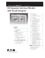
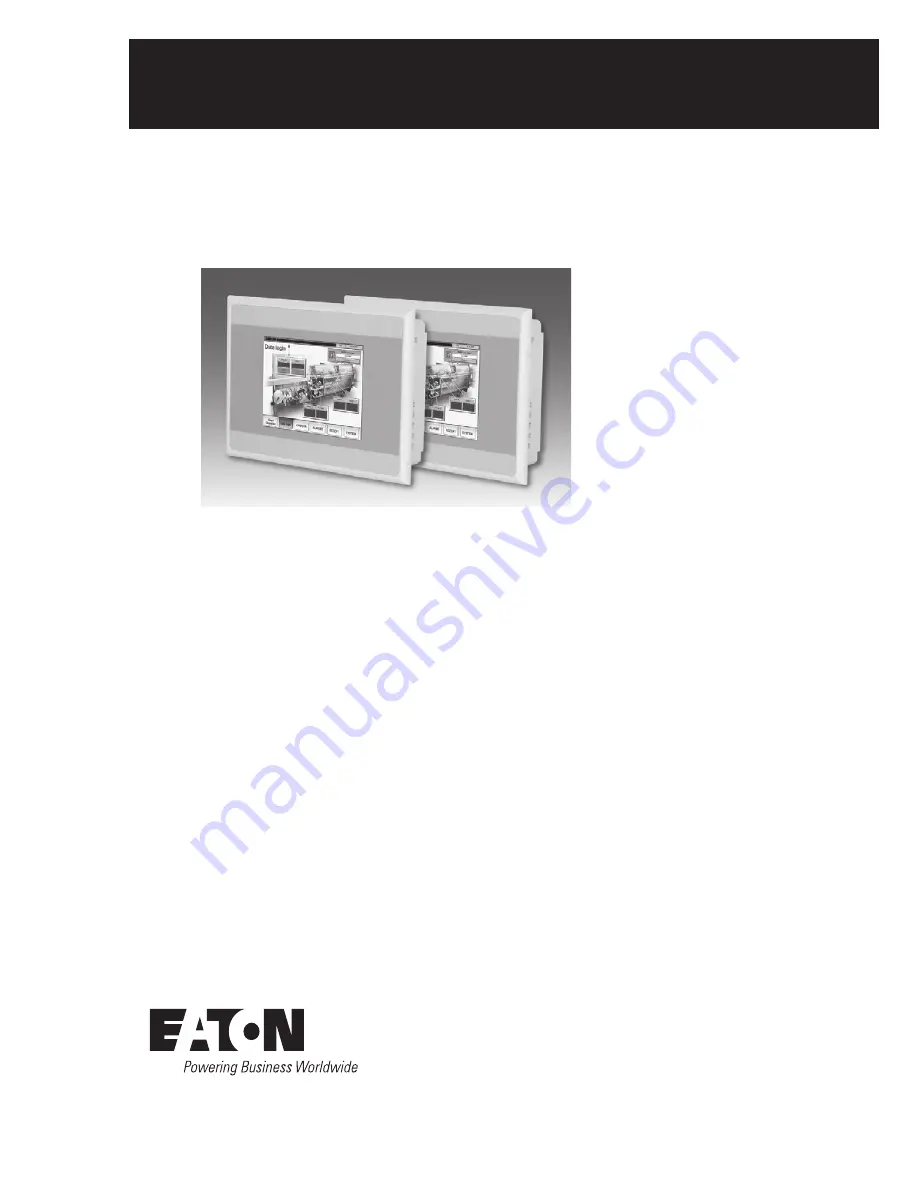
XV Operator Interface Models  

with Visual Designer

Contents

1.  General ............................................................. 2

1.1  Document Index  . . . . . . . . . . . . . . . . . . . . 2
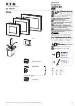
1.2  Scope of Supply . . . . . . . . . . . . . . . . . . . . . 2

2.  Installation ....................................................... 2

2.1  General Remarks to Wiring . . . . . . . . . . . . 2
2.2  Starting the device . . . . . . . . . . . . . . . . . . . 2
2.3  Switching off the device . . . . . . . . . . . . . . . 2
2.4  Calibrating the Touchscreen . . . . . . . . . . . . 2
2.5  Ethernet . . . . . . . . . . . . . . . . . . . . . . . . . . . 2

2.5.1  Examining and Adjusting the  


IP-Address of the Unit . . . . . . . . . . . . 3

2.5.2  Wiring . . . . . . . . . . . . . . . . . . . . . . . . . 3
2.5.3  Test the Ethernet Connection  . . . . . . 3

3.  The first VISUAL DESIGNER Project ............. 3

3.1  Creating a new Project . . . . . . . . . . . . . . . . 4
3.2  Select a Display Resolution . . . . . . . . . . . . 4
3.3  Saving Your Project . . . . . . . . . . . . . . . . . . . 4

3.4  Tags - Overview . . . . . . . . . . . . . . . . . . . . . 4

3.4.1  Tag Categories . . . . . . . . . . . . . . . . . . 5
3.4.2  Tag Nomenclature  . . . . . . . . . . . . . . . 5
3.4.3  Visual Designer tag data types  . . . . . 5
3.4.4  Tag Scope. . . . . . . . . . . . . . . . . . . . . . 5
3.4.5  Declaring Tags  . . . . . . . . . . . . . . . . . . 5
3.4.6  Visual Designer tag arrays . . . . . . . . . 6
3.4.7  Visual Designer Class Tags . . . . . . . . . 6
3.4.8  Defining Tag Parameters  . . . . . . . . . . 7
3.4.9  Accessing tag parameters  


during development . . . . . . . . . . . . . . 7

3.4.10  Accessing tag fields  


during runtime . . . . . . . . . . . . . . . . . . 8

3.4.11  Add a tag to your Project . . . . . . . . . . 8

3.5  Application Screens . . . . . . . . . . . . . . . . . . 8

3.5.1  Creating a Standard Screen . . . . . . . . 8
3.5.2  Saving the Screen . . . . . . . . . . . . . . . 9
3.5.3  Selecting the Application  


Startup Screen . . . . . . . . . . . . . . . . . . 9

3.5.4  Visual Designer Toolbars for  


Screen Objects  . . . . . . . . . . . . . . . . . 9

3.5.5  The Text I/O Object  . . . . . . . . . . . . . 10
3.5.6  The Pushbutton Object  . . . . . . . . . . 11
3.5.7  The Button Object with Colors  


and Command Properties  . . . . . . . . 11

3.5.8  Selecting the Startup Screen . . . . . . 12
3.5.9  Testing the Application . . . . . . . . . . . 12
3.5.10  Configuring a Communications  


Driver and Linking Tags  . . . . . . . . . . 13

3.5.11  Verifying the Application and  


Creating the Runtime Web Pages . . 14

3.5.12  Connecting to the XV Unit  


with Ethernet . . . . . . . . . . . . . . . . . . 14

3.5.13  Downloading Visual Designer  


Runtime Files . . . . . . . . . . . . . . . . . . 15

3.5.14  Downloading Visual Designer  


Project Files . . . . . . . . . . . . . . . . . . . 15

4.  Operation from the Internal Flash or  

  SD-Card .......................................................... 15

4.1  Switch between Booting from the  


Internal Flash or SD-Card . . . . . . . . . . . . . 15

4.2  Version Change of the  


Operating System  . . . . . . . . . . . . . . . . . . 15

Summary of Contents for XV-102 Series

Page 1: ...fining Tag Parameters 7 3 4 9 Accessing tag parameters during development 7 3 4 10 Accessing tag fields during runtime 8 3 4 11 Add a tag to your Project 8 3 5 Application Screens 8 3 5 1 Creating a S...

Page 2: ...boot If the device does not boot up and or if an error message appears while starting booting the device see Chapter Troubleshooting and fault rectification manual Operating Instructions XV102 152 1 T...

Page 3: ...does not reply and instead returns Request timed out then contact your network administrator for troubleshooting assistance Further information Hardware manual XV 102 152 system 1 2 Further informatio...

Page 4: ...screen you have the option of defining the resolu tion of an individual Screen If you are creating a Screen Group for a Multiple Document Interface MDI interface i e a collection of smaller Screens t...

Page 5: ...g False or True Integer Four bytes Signed integer number positive negative or zero Equivalent to the C type signed long integer with a range of 2147483647 to 2147483647 Real Floating point eight bytes...

Page 6: ...the same data type have the same name and use an index to uniquely identify a tag that is an element member of the array The use of array tags can simplify the method used to access multiple data item...

Page 7: ...curs These values can be changed during runtime Quality Indicates whether an improper evaluation occurred e g divide by 0 or if there was a bad read from a communication driver e g read or write error...

Page 8: ...m or Trend Worksheet those values will be written into the fields shown here 3 4 10 Accessing tag fields during runtime Accessing Tag Fields Parameters during runtime is straightforward and is done th...

Page 9: ...r Save As when the Screen has not been previously been saved or if you select Save As with an existing Screen All screen files are automatically saved in the Screen subfolder in the Note N application...

Page 10: ...appear Text icon Text Data Link icon You may modify the properties for alignment colors fonts and even the text caption from this property dialog To add the Text Data Link property to this object clic...

Page 11: ...n as shown below and hit OK Make sure to select copy the same hmiPB1 tag in the Indicator property Note that properties which have no ellipsis button to open the Object Finder dialog can still open th...

Page 12: ...s properties that have been added you can click on the property you want to remove with the object selected with or without the dialog displayed and it will toggle the properties off With the Button o...

Page 13: ...ver you want to add click on the driver and then click the Select but ton Then click OK For purposes of this manual we will use the Eaton protocol labelled MODBUS EATON Protocol RTU ASCII CE v1 1 This...

Page 14: ...pace and cleans up the application prior to downloading Then click on Verify When verify is complete the following dialog will be displayed Click OK then Close on the Verify Project dialog Next to cre...

Page 15: ...om internal flash or from the SD card Operation from the SD card The OS that is stored on the SD card is loaded The runtime for Visual Designer and PLC are started from the SD card The Visual Designer...

Page 16: ...e stored in this directory To perform a version change of the operating system the operat ing system image file XV102 BIN must be copied to the directory InternalStorage OS on the XV After this the ch...

Reviews: