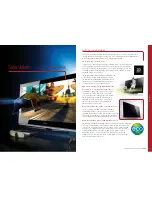
Pioneer PDP-50MXE1, User Manual
The Pioneer PDP-50MXE1 User Manual is readily available for download, completely free of charge, at our website. This comprehensive manual ensures that you can easily set up and navigate through the features of your Pioneer PDP-50MXE1 television, providing an optimal viewing experience. Get your free manual today at manualshive.com.
Share
Download


Reviews:
No comments
Related manuals for PDP-50MXE1

CPL10
Brand: Q-NEX Pages: 2

PCD7.D412DTPF
Brand: Saia Burgess Controls Pages: 73

LCD3215 - MultiSync - 32" LCD Flat Panel Display
Brand: NEC Pages: 37

LCD4215 - MultiSync - 42" LCD Flat Panel Display
Brand: NEC Pages: 10

LCD3215 - MultiSync - 32" LCD Flat Panel Display
Brand: NEC Pages: 2

LCD4215 - MultiSync - 42" LCD Flat Panel Display
Brand: NEC Pages: 2

LCD3215 - MultiSync - 32" LCD Flat Panel Display
Brand: NEC Pages: 2

LCD3215 - MultiSync - 32" LCD Flat Panel Display
Brand: NEC Pages: 9

MultiSync V462-TM
Brand: NEC Pages: 2
BRAVIA KDL26BX300
Brand: Sony Pages: 7

BRAVIA KDL-V32XBR1
Brand: Sony Pages: 2

BRAVIA KDL-60NX800
Brand: Sony Pages: 2

BRAVIA KDL26BX300
Brand: Sony Pages: 24

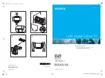
Bravia KLV-22BX300
Brand: Sony Pages: 32
Bravia KLV-S19A10U
Brand: Sony Pages: 38

Bravia KLV-32BX300
Brand: Sony Pages: 39

BRAVIA KDL-S40A11E
Brand: Sony Pages: 32
Bravia KDL-W40A12U
Brand: Sony Pages: 43


