background image

10

CleanFire Owners Manual

2016

Choosing Location

When installing your WoodMaster, keep in 

mind the direction of the winds during heating 

months. Try to place the boiler in an area where 

exhaust will not be a problem for yourself or 

any surrounding neighbors. For either indoor or 

outdoor installation.

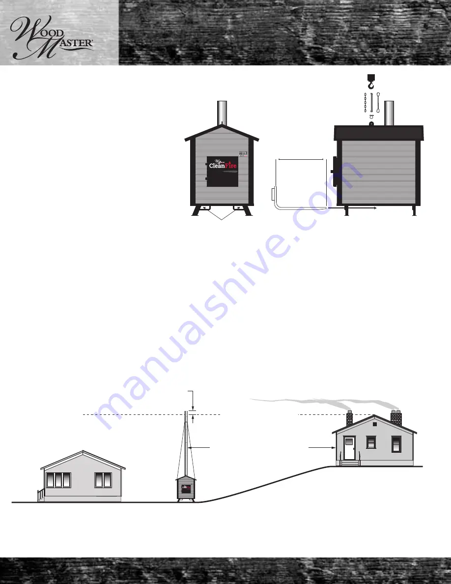
Only lift the CleanFire by the overhead hanger, 

or with a fork lift from below, placing the forks 

inside of the loops on the legs. NEVER LIFT THE 

CLEANFIRE BY THE THROAT/FIRE CHAMBER. 

THIS WILL DAMAGE THE UNIT. 

Clearances

There must be a minimum clearnace from combustibe materials when the boiler is installed. There must be 6” 

from either side, 48” from the front, 36” from the rear and 18” from the chimney connector. More room should be 

allowed to make cleaning and maintenance easier. Keep the space underneath the boiler open. Keep the area in 

front of the door clear. This space must be at least 16” in the front and 8” on either side. 

For Outdoor Installation

LOCATION: It is recommended that the unit be located with due consideration to the prevailing wind direction. 


•  When using more that 4 feet of chimney extension external support is needed.


•  Should be located greater than 100 feet from any residence not served.


•  If located between 100 and 300 feet to any residence not served, it is recommended that the 


  stack be at least 100% of the height of the peak of the residence, plus an additional 2 feet.


•  Should be located 10 feet from any combustible materials.

Always remember to comply with all applicable state and local codes.

For Indoor Installation

LOCATION: It is recommended that the unit be located with due consideration to the prevailing wind direction. 


•  When using more that 4 feet of chimney extension external support is needed.

Installation

Forklift

Overhead Lifting

Forks

Residence not

served by furnace

2 feet 

Residence

served by furnace

Minimum of 100 feet

Chimney height

should be 2 feet above roof line

Summary of Contents for CleanFire 400

Page 1: ...oor Wood Fired Hydronic HEater CleanFire 400 OWNERS MANUAL Retain this manual Northwest Manufacturing Inc 600 Polk Ave SW Red Lake Falls MN 56750 www woodmaster com 800 932 3629 Manual PN 7994 505 Rev 2 1 4 ...

Page 2: ...s manual for as long as you own your CleanFire All installation and operations must follow STATE and LOCAL CODES for wiring and firing of this unit These CODES may differ from this manual Installation must be performed by a qualified installer Follow the manual carefully Follow the recommended cleaning and maintenance The WoodMaster CleanFire is designed to be operated in a pressurized system Make...

Page 3: ...uring the operation Temperatures at other points for example chimney tube access box door water lines can be very high The WoodMaster CleanFire must be operated exclusively according to the guidelines for planning assembly regulations statutes and product related instructions The manufacturer is not liable for damages and their results if they occurred due to improper assembly operation applicatio...

Page 4: ...or preventing or adequate water capacity within the boiler to prevent damage to the boiler from loss of circulation due to electrical power failure 6 Be capable of being installed without changing the function of the controls or rewiring of the original boiler A wiring interconnection may be used The electrical system of both boilers shall be powered from a single branch circuit Warning Always dis...

Page 5: ...burnwise index html for information on wood fuel fired appli ances as well as a list of approved appliances Legal name of original manufacturer Northwest Manufacturing Inc 600 Polk Ave SW Red Lake Falls MN 56750 800 932 3629 www woodmaster com US ENVIRONMENTAL PROTECTION AGENCY Certified to comply with 2020 particulate emission standards using cord wood Date Code _____________________ CleanFire 40...

Page 6: ...acity _______ Mfg Serial No ____________ Year built_______ 30 psi 250 20XX XXXXXX 100 LB HR 31 Certified by Northwest Manufacturing Inc MAWP Water _________ Maximum Water Temp _________ Heating Surface _________boiler Heating Surface _________Sq Ft water wall Heating Surface _________extended Ext HS generating cap _______ Minimum relief valve capacity _______ Mfg Serial No ____________ Year built__...

Page 7: ...n garbage gasoline fuel oils or other flammable liquids or materials DO NOT use chemicals or fluids to start unit firing DO NOT store fuel or other combustible materials within marked installation clearances DO NOT connect this unit to a chimney or flue serving another appliance Inspect and clean flues and chimney regularly For safety leave fuel door and ash removal doors tightly closed during ope...

Page 8: ...ced parallel to the fire chamber wall The pieces of wood should be stacked as tightly as possible whereby the face of the wood should NOT touch the fire chamber wall This ensures proper air flow DO NOT burn any large round pieces of wood DO NOT burn any green wood or any wood that is above the 25 moisture limit Water Content The maximum permitted water content is 25 Bark Content The maximum permit...

Page 9: ... corrosion and no need for ceramics Pre heated combustion air Made from 8 gauge steel Very long lasting due to no creosote Extremely easy maintenance can be cleaned in a few minutes COMBUSTION PROCESS Primary and secondary air ducts equipped with 2 dampers to allow for optimal burn The remaining gasses leaving the combustion chamber are mixed with oxygen in the injection tube ensuring a complete c...

Page 10: ...door clear This space must be at least 16 in the front and 8 on either side For Outdoor Installation LOCATION It is recommended that the unit be located with due consideration to the prevailing wind direction When using more that 4 feet of chimney extension external support is needed Should be located greater than 100 feet from any residence not served If located between 100 and 300 feet to any re...

Page 11: ... cannot be reduced or enlarged A draft controller may be used to allow proper flow The draft controller must be installed as close to the boiler as possible The chimney draw must be no greater than 05 inches of water Measure the draft at the bottom of the chimney just above the flue connector by drilling a hole in the c himeny that is sized for your measuring device Properly plug the hole when com...

Page 12: ...se only water line approved by North west Manufacturing through your Woodmaster Dealer Oxygen barrier line is recommended NOTE If lines travel under a driveway or where heavy equipment travels the line should be buried two to three feet deep If lines travel through a low or wet area they should be insulated and installed in a water tight piping PVC Note Leave a minimum of three feet of water line ...

Page 13: ...rom the factory An air bleeder or pressure relief valve must be installed on the water tank A pressure gauge may be in stalled on the boiler It is recommened to install the pump inside the building that the boiler is serving WARNING Do Not install close off valves on the boiler closing of the loop while in operation can create danger ous conditions Follow all state and local codes for installing a...

Page 14: ...iler are accessed by removing the side panel on the bottom left side of the boiler Make sure the boiler is off and cool and the water pump is off and the pressure has be relieved from the sytem before attempting to service any part of the plumbing on the boiler Pressure Relief Valves Pressure Relief Valves Hot Supply Hot Supply Cold Return Cold Return Drains Drains LWCO Location LWCO Location ...

Page 15: ...tting of the heat exchanger and exits the top fitting which returns to the boiler If the plenum is too large or too small it must be altered to fit the heat exchanger properly Note The water to air heat exchanger must be in stalled below any existing off peak electric coils already in the plenum After the installation of the WoodMaster add on water to air exchanger the air flow may need to be incr...

Page 16: ...eturn WoodMaster Water to Water Heat Transfer Unit Circulating Pump for Existing Hot Water Heating System Existing Hot Water Boiler Cold Water Return from Heat Exchanger Domestic Water Supply for filling boiler Cold Water Return to WoodMaster Filling With Water Connect a garden hose between a domestic water supply and the boiler fill valve 0020 325 which was installed in the cold water return line...

Page 17: ... Do not use your fingernails or sharp objects to press the buttons as this will cause damage to the membrane Switching the Boiler On Once the boiler is properly plumbed and water has been added to the system it can be switched on and fired Press and hold the Button to start the boiler Once started See the Firing section for igniting the fire Controller Navigation Press and hold the button to acces...

Page 18: ...tomer service representative may ask for these values to diagnose a failed thermocouple Do not attempt to calibrate the Thermocouple as a jumper must be installed for calibrating DO NOT ATTEMPT TO CREATE A JUMPER THIS WILL CAUSE DAMAGE TO THE BOARD AND VOID YOUR WARRANTY This screen will allow you to view the boiler water pressure No changes can be made on this screen Select Exit to return to the ...

Page 19: ...d news paper to fire your boiler Caution Load your boiler carefully and avoid any hard contact between the fuel and the fire chamber the fire chamber throat and the fire chamber door NEVER use fluids or chemicals to start the fire Then take the dry small sized and easily combustible material and arrange it parallel to the fire chamber side making sure to fully cover the bottom of the fire chamber ...

Page 20: ...alyst has reached 750 on the display the boiler should enter burn mode more fuel can be added at this time Make sure all fuel used meets the guidelines in this man ual and is loaded parallel to the sides of the fire chamber 125 lbs of seasoned hardwood such as oak or maple will give an 8 hour burn at max draw Other hardwood and softwood species can be used but may result in shorter burn times as t...

Page 21: ... the fire at all times At certain points in the burn the fire may chase oxygen out of the door when it is opened The WoodMaster CleanFire is equipped with a two stage latch that will prevent burn back when used properly It may be necessarry to rake and level the coal bed druing the burn cycle under heavy loads to maintain output When raking bring any large unburnt pieces of wood to the center of t...

Page 22: ...manual Level the coal bed if needed Load the fire chamber with cut split and seasoned wood laying it parallel to the fire chamber sides Close the door completely and activate the reload function on the controller This will purge any excess oxygen from the boiler Once the oxygen has been purged and the catalyst is at or above a set value the boiler will automatically enter burn mode On lower heat l...

Page 23: ...sed container of ashes should be placed on a noncombustible floor or on the ground well away from all combustible materials pending final disposal If the ashes are disposed of by burial in soil or otherwise locally dispersed they should be retained in the closed container until all cinders have thoroughly cooled Maintenance Removing the Ash From the Fire chamber daily or as needed Open the fire ch...

Page 24: ...the fire chamber separating the coals from the ash Note the hot coals can be removed and temporarily place in a metal container Once all of the ash is re moved place the hot coals back in the fire chamber Shovel the ash out of the front of the fire chamber Take care as to not damage the primary air channels when removing the ash Pull the coals from the back of the fire chamber to the front Shovel ...

Page 25: ...the boiler is cool and power is discon nected remove the chimney coupling on the top of the heat exchanger top access box Maintenance This wood heater contains a catalytic combustor which needs periodic inspection and replacement for proper oper ation It is against federal regulations to operate this wood heater in a manner inconsistent with operation instruc tions in this manual or if the catalyt...

Page 26: ... sensors on the side of the box Vacuum all ash from the tube box including the door and any remaining ash in the heat transfer tubes Make sure the turbulators are in place and close the top door when cleaning is complete Reconnect the draft fan wires and the chimney coupling Lift the lid off and back taking care not to damage the draft fan wires Set the lid aside where it will not be dam aged Main...

Page 27: ...the two knobs Vacuum or sweep the ash from the ash box Replace the cover when finished Monitor the pressure of the water in the boiler daily If the pressure is low add water There is no need to drain and flush the boiler when proper boiler treatment is used Maintenance ...

Page 28: ...umulated it should be removed to reduce the risk of a chimney fire Since the CleanFire has a fire chamber that is surrounded by air the metal surface of the chamber is allowed to heat up with the fire and will prevent creosote from building up during normal opertaion with seasoned wood Due to the use of a catalytic converter the smoke in the exhaust that would potentially create creosote buildup i...

Page 29: ...he catalyst cannot reach and maintain a temperature above 700o F and if the boiler is not maintaining normal heat ouput the catalyst may be failed and in need of replacement To access the catalyst remove the heat exchang er top lid as described previously in this manual See the warranty section to determine if your catalyst is covered under warranty Do not attempt to burn the CleanFire without a w...

Page 30: ...elow the catalyst Replace if damaged Install the new seal as shown Maintenance Place a new clean catalyst in the housing as shown Small gaps in the seal are acceptable as the seal will expand the first time the boiler is fired Do not allow any debris to sit on the catalyst as this can create hot spots and will reduce the life of the catalyst Replace all insulation and the catalyst cover Make sure ...

Page 31: ...art the new rope in the same location as the old one and press the rope into the channel on the door Clean the sealing surface on the boiler before closing door Door Seal Daily Yearly The front door as well as the rear access doors must seal properly to ensure proper combustion The front door seals should be inspected for damage or fatigue each time the boiler is loaded The heat exchanger access d...

Page 32: ...ide a portion of the new rope under the plate making sure to leave enough of the rope exposed to ensure a good seal Once the rope is in place secure the two nuts to 8 ft lbs The heat exchanger doors should seal tightly with no vis ible signs of air leakage If a leak is detected or if the rope becomes hard and is no longer flexible the seal should be replaced The same process is used for the upper ...

Page 33: ...y old caulking and clean any debris from the channel once the rope is removed Start the new rope in the same location as the old one and press the rope into the channel on the door Clean the sealing surface on the heat exchanger before replac ing the door Once the debris is cleaned lay a small bead of silicone in the corner of the dorr as shown the Silicone must remain behind the rope so use the s...

Page 34: ...ntrol will allow for operation To test during normal operation press the test button on the side of the LWCO The light should turn red and the boiler operation should stop Release the button to restart normal operation The LWCO should be tested once a year or any time the boiler is fired after an extended down period Low Water Cutoff Cleaning The LWCO should be cleaned every 5 years or if indi cat...

Page 35: ...t 10X10 Junction Grn Wht Blk 5A Master Solenoid Damper 0 Primary L1 N Earth Inducer Fan Secondary Primary Damper 1 Secondary LED Light LED Light Air Box 0 50 PSI OLED Front Display 3210 TC Wht Catalyst Thermocouple Return RTD Supply RTD Red Yel Blu Red Blk O2 1 0 RTD Grn Gry Gry 200ºF Snap Disc Low Water Cutoff N H Wht Blk Grn Brn Brn Brn Brn 8 15 16 Red Yel 3210 Side View Front TC All wiring shou...

Page 36: ... may be added 9 Check the catalyst temperature If the catalyst is not able to maintain a temperature of 700o F or higher then the catalyst may be plugged or failed If Boiler Pressure Valve Releases 1 Check fire chamber door Be sure door was not left open 2 Check fire chamber door seal Make sure the door has a tight seal 3 Check the draft fan and air dampers Make sure they are operating properly 4 ...

Page 37: ...d restart the unit according to this manual In the Event of Lock Out 1 Wait for the unit to come out of lockout mode 2 Before proceeding check the boiler for damage 3 Check the display for errors 4 If no errors are present check the fire chamber and inspect the door seals 5 If no damge is present restart the unit according to this manual NOTE If boiler boiled water out and air entered lines this c...

Page 38: ...onnect the power and check the Thermocouple connections If this does not work Replace the Thermocouple Catalytic Convertor thermocouple Reads same as board temperature 1 F for 5 consecutive minutes Snap Error Snap disc triggered or low water cutoff has triggered Wait for boiler too cool thus allowing the snap disc to reset If the boiler does not reset replace the snap disc Check the door seals for...

Page 39: ...r will give you a 10 discount on the purchase of a new WoodMaster Boiler Boiler only Years Twenty One through Twenty Five 21 25 WoodMaster will give you a 5 discount on the purchase of a new Wood Master furnace Once a defect is determined repair or replacement of the Pressure Vessel in a whole or part will be at the sole discretion of Northwest Manufacturing Inc LIMITED ONE 1 YEAR WARRANTY ON THE ...

Page 40: ... contact with the flame will not be covered under this warranty WARRANTY TERMS The Warranty shall also be subject to the following terms and conditions I The Boiler must have been installed by a Certified Contractor II The Boiler must have been properly maintained cleaned and serviced during the Warranty Periods in accordance to the manual III This Warranty is non transferable and only covers the ...

Page 41: ...Northwest Manufacturing Inc 600 Polk Ave SW Red Lake Falls MN 56750 Northwest Manufacturing Inc 600 Polk Ave SW Red Lake Falls MN 56750 PLACE POSTAGE HERE Cut here and mail registration card ...

Page 42: ...ame Address City State Zip Phone Serial Number Located on UL Sticker How did you learn about our product Radio Newspaper Internet TV Print Other Would you like information on other products from Northwest Manufacturing Inc Yes No I have read the owners manual and understand the proper usage of my WoodMaster CleanFire Signature Printed Name Fold Fold Fold Fold Fold Fold Fold Fold Fold Fold Fold Fol...

Page 43: ...Power Output 102 400 BTU 30 kw Weight 2885 Pounds 1180 kg Boiler Height 84 213 4 cm Boiler Width 56 142 2 cm Boiler Depth 74 5 189 cm Water Jacket Capacity 55 Gallons 227 3 L Fire chamber Opening 16 5 x19 42x48 3 cm Fire chamber Volume 12 5 cubic feet 354 L Model Number CleanFire 400 All specifications are approximate and may change without notice Specifications ...

Page 44: ...Northwest Manufacturing Inc 600 Polk Ave SW Red Lake Falls MN 56750 www woodmaster com 800 932 3629 Manual PN 7994 505 ...

Reviews: