background image

57

Model Ci User Manual

4. Operating Procedures

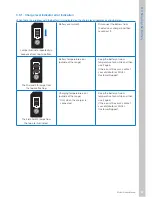
When the power turns on, first the WHILL logo appears 
on the display,  and next the current speed setting is 
displayed. After some time, the display changes to the 
battery charge level indicator.
To check the speed setting again, either turn the power 
off and back on, or else press the speed select buttons 
and adjust the speed.

WHILL logo

Speed setting

Battery charge 

level

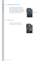
4.4.1.  Checking the battery charge level

The battery charge level is shown on the 
display as a number in the range of 0 - 100, 
changing in increments of 1.
When fully charged, the charge level is shown 
as “100”.

Summary of Contents for Ci

Page 1: ...WHILL Model Ci User Manual ...

Page 2: ......

Page 3: ...his manual in a location where it can be referred to whenever needed This manual contains information that is protected by patent rights and copyrights It may not be reproduced in part or in whole without explicit written permission from WHILL Inc The contents of this manual may be changed in the future without notice Use of this device in ways not consistent with the contents of this manual may r...

Page 4: ...ions which if not observed may result in minor or moderate injury or in property damage Symbol mark indications Symbol Description Indicates a prohibited act Indicates that disassembly of the device may result in electric shock or other injury Indicates a required act Indicates a risk of electric shock Indicates a risk of rupture Other indications Symbol Description Indicates precautions or refere...

Page 5: ...ssories 36 3 Charging the Battery 37 3 1 Battery Components 39 3 2 Charging Procedure 40 3 2 1 Charging with the battery installed in the base 42 3 2 2 Charging with the battery removed 43 3 2 3 Power charge indicator indications 46 3 3 Checking the Charge Level of the Removed Battery 46 3 3 1 Charge level indicator error indication 47 3 4 Battery Inspection and Replacement 48 4 Operating Procedur...

Page 6: ...asket 67 4 8 Locking the Device 69 4 8 1 Locking 69 4 8 2 Unlocking 70 4 9 Using the USB port 71 5 Assembly Adjustment and Disassembly 73 5 1 Component List 73 5 2 Assembly Procedures 75 5 2 1 Assembling the Front drive base and Rear drive base 76 5 2 2 Installing the storage basket 77 5 2 3 Installing the seat assembly 78 5 2 4 Installing the battery 81 5 3 Adjustment Procedures 82 5 3 1 Adjustin...

Page 7: ...hold each component 103 7 Downloading the Smartphone App 105 8 Maintenance and Inspection 107 8 1 User Maintenance 107 8 2 Replacing the Smart Key Battery 108 8 3 Reinstalling the Controller Knob 109 8 4 Inspection 110 8 5 Repairs Maintenance and Parts Replacement Performed by the Manufacturer or Distributor 110 8 6 Disposal 111 9 Troubleshooting 113 10 Specifications and Test Results 115 10 1 Spe...

Page 8: ...6 ...

Page 9: ...ave an implanted pacemaker implanted defibrillator or other electrical medical device on their bodies must stay a minimum of 8 inches 20 cm away from the magnetic connectors The magnetic connectors are located at the connection between the seat assembly and rear drive base and the connection between the battery and rear drive base The charge of the magnetic connectors may have an adverse effect on...

Page 10: ... the device If the brakes are released there is a risk that the device may start moving and tip over If your body is not stable in the seat be sure to use the lap belt if purchased There is a risk of falling out of the device If the device you are using does not have a lap belt contact your distributor When operating the device while wearing gloves be careful that the gloves do not become caught T...

Page 11: ... on a downhill slope release the controller knob early and make sure that you stop with a sufficient margin of extra space The brake stopping distance is longer when on a downhill slope There is a risk that you may be unable to stop in the intended position causing an unexpected accident Be sure to turn Off the power before releasing the brakes There is a risk that the device may start moving caus...

Page 12: ... in the bottom of the back support or the connection There is a risk of injury When assembling or disassembling the front drive base and rear drive base be sure to grasp the handle A There is a risk of injury caused if fingers are caught Perform assembly and disassembly in a flat level location There is a risk of unexpected accident Be sure to replace the anti tip bar if it gets deformed There is ...

Page 13: ...risk that these components may not be visible resulting in incorrect operation and unexpected accident Do not touch the battery connectors allow them to become wet or bring any metal or other foreign objects close to them There is a risk of injury and of damage to the device or its components Do not remove the motor controller connectors and caps There is a risk that a short circuit may occur by i...

Page 14: ...or other moving component There is a risk that clothing may be caught in these components preventing you from controlling the device Do not sit on the controller knob place the removed seat assembly upside down or apply an excessive load to the controller knob There is a risk that the controller knob may be damaged rendering the device inoperable Do not press the buttons with strong force or using...

Page 15: ...stments or repair that is not explained in this manual If the customer performs such acts him herself there is a risk of a serious effect on safety Consult with your distributor when adjusting the seat length or arm position Do not disassemble adjust or repair the device or lift the device up while it s in use There is a risk of damage to the device causing an unexpected accident Do not use the de...

Page 16: ...or other substance charging will not be possible When using your own cushion for safety be sure to use a cushion that has passed a fire resistance test If the power does not turn on check the magnetic connectors The magnetic connectors are located at the connection between the seat assembly and rear drive base and the connection between the battery and rear drive base Pay attention to the followin...

Page 17: ...s a risk of injury caused when a hand gets caught in the device When assembling check that the magnetic connectors are not dirty If a magnetic connector is dirty electricity may not flow through it and the power may not turn on The magnetic connectors are located at the connection between the seat assembly and rear drive base and the connection between the battery and rear drive base Pay attention...

Page 18: ...f a component gets worn or requires replacement contact your distributor or manufacturer There is a risk of damage to the device that renders it inoperable When disposing of the device and its components be sure to follow the rules of the local municipality If there is anything that is unclear consult your distributor or WHILL Customer Support Device battery should be charged in a well ventilated ...

Page 19: ...ace a load on the directional controller assembly or scratch it with a sharp object There is a risk that the directional controller assembly may become damaged rendering the device inoperable Do not throw step on or otherwise subject the removed control assemblies to strong impact and or immerse them in water There is a risk that the switch or directional controller assembly may become damaged ren...

Page 20: ...a cable inside the seat post Pulling forcefully on the seat post may break the cable inside it Do not press a sharp object against or apply a load to the seatback cables located on the bottom of the seat There is a risk of breaking the cables Do not store the device for long periods in a location where there is much dust or sand near the ocean or in a hot spring area There is a risk of foreign sub...

Page 21: ...ssemblies Doing so may cause malfunction of the control assemblies Do not remove the labels The labels contain important information Do not attempt to grease the moving components or connectors of the Device There is a risk that the stickiness of such substances may cause sand or other foreign substance to enter the device causing device malfunction Do not drive the device at speeds of 5 mph or hi...

Page 22: ... injury or electric shock Doing so will also invalidate the device warranty Do not use an extension cord with the charger There is a risk of electric shock short circuit and fire Do not pull the connector cord with excessive force There is a risk of electric shock short circuit and fire Charge the device using a household power supply There is a risk of electric shock short circuit and fire Charge...

Page 23: ... If it is left uncharged there is a risk that the battery may get excessively depleted Do not charge the battery while the brakes are released There is a risk that the device may move causing an unexpected accident Do not store the device for extended periods with the battery removed There is a risk of battery deterioration If it is unavoidably necessary to store the without the battery be sure to...

Page 24: ...ely affect the operation of electronic devices This phenomenon is known as electromagneticic interference EMI or radio frequency interference RFI Radio waves may interfere with the control functions of this device If the device moves or stops when the device controller is not operated or if the device operates in a way different than intended take the following actions Write down the controller op...

Page 25: ...r distances to the transmitting antenna This electromagneticic field can cause problems for users of electric equipment What kind of movements should I expect if a personal electric vehicle is affected by EMI or RFI EMI and RFI undergo extremely large dynamic changes and may affect a powered device depending on conditions such as the following Radio wave frequency and strength Structure of the pow...

Page 26: ... Magnetic connectors are located at the device connection between the seat assembly and rear drive base and the connection between the battery and rear drive base The magnetic field of the magnetic connectors may have an adverse effect on electrical medical devices Persons who have an implanted pacemaker implanted defibrillator or other electrical medical device on their bodies must stay a minimum...

Page 27: ... release lever lock position and unlock position Check that the base release lever is locked before driving F Indicates precautions Be sure to read the User Manual before use Check that the brakes are locked before use Do not leave this device with the brakes released Do not use the device as a seat in an automobile or other vehicle G The maximum storage basket load is 13 lbs 6 kg If a larger load...

Page 28: ...onnecting the connectors from the directional controller assembly and control pad K Indicates the battery removal key lock position and unlock position L 3 4 5 Indicates the device disassembly procedure M Indicates the seat assembly insertion position when installing the seat assembly onto the rear drive base N Indicates the procedure for adjusting the back support angle 90 95 or 100 O Indicates t...

Page 29: ...27 Model Ci User Manual 1 Safety Precautions A B H D C D 1 3 2 Label application locations The position where each label is applied is as shown in the figure below Device ...

Page 30: ...28 Model Ci User Manual 1 Safety Precautions J I D K E F L M N Seat assembly top view ...

Page 31: ...29 Model Ci User Manual 1 Safety Precautions Storage basket D D O P Parts with seat cushion removed G ...

Page 32: ...30 Model Ci User Manual 1 Safety Precautions 1 4 Location of Serial Number The location of the serial number is shown in the figure below Connection with battery removed Serial number ...

Page 33: ... or damaged components If any component is missing or if the device is damaged contact the distributor or WHILL Customer Support WHILL Model Ci including battery and storage basket Charger Smart key if included User Manual this manual Quick Start Guide Be careful not to scratch the exterior when opening the package 2 2 Names and Functions of Parts External view A C B D E F H I J K G L M N O P ...

Page 34: ... The directional controller assembly c and control pad e are installed on the end C Directional controller assembly This is the round unit where the directional controller assembly is installed It controls the movement forward backward left and right The degree of controller knob inclination can also control acceleration and deceleration D Arm rest This is the device arm rest Controller Knob ...

Page 35: ...following functions 1 Speaker 2 Display 3 Speed increase button 4 Speed decrease button decelerate 5 Horn 6 Power button F Seat assembly release lever This lever is used to separate the seat assembly from the rear drive base G Storage basket This basket is used to carry storage items It is installed onto the front drive base H Rear wheel This is the device rear wheel 3 4 5 6 2 1 ...

Page 36: ...e release levers This lever is located near each of the rear wheels below the seat There are two such levers in total K Foot rest This platform supports the user s feet when the user is sitiing on the device L USB port This is the port for connecting the USB cable M Rear tail light This is a red vertical LED light located on the battery ...

Page 37: ...ion battery supplied with the device O Base release lever This lever is used to separate the rear drive base from the front drive base P Anti tip bar This bar prevents the device from tipping over to the rear Charger This is used to charge the battery Smart key if purchased This is used to lock the device ...

Page 38: ... About this Product 2 3 Accessories Be sure to use only genuine accessories For the accessories that can be installed onto this device contact your distributor or WHILL Customer Support Or visit the WHILL Website http whill us ...

Page 39: ...y charge the battery before use Reduce the weight of the storage items as much as possible Plan your route to avoid hills and obstacles Maintain constant speed and avoid sudden stops and frequent stops WARNING Carefully read the explanations in this manual regarding the battery and charger and follow the instructions If used incorrectly there is a risk of injury or damage to the battery or charger...

Page 40: ... insufficient charge level from occurring Charge in a well ventilated space that is free of flammable gases and that is at least twice the size of the device There is a risk of explosion or other accident if the space is filled with flammable gas or if ventilation is insufficient Do not leave the device for a long time with the battery removed There is a risk of battery deterioration If it is unav...

Page 41: ...y Components Battery This device uses a lithium ion battery with a voltage rating of 25 2 V Battery charging port with cap Handle Rear tail light Charge level indicator Battery charge level button Power charge indicator AC receptacle DC connector cord Charger ...

Page 42: ...ll outlet for a long period of time In an emergency the device can be driven when charging has not been completed WARNING Do not while your body is in contact with the battery or charger There is a risk of low temperature burns Do not touch the battery connectors allow them to become wet or bring any metal or other foreign objects close to them There is a risk of injury and of damage to the device...

Page 43: ...f the device is not being used for a long period be sure to charge it at least once every 3 months If it is left uncharged there is a risk that the battery may get excessively depleted Use only the charger and AC connector cord that were provided with the device Using a charger or AC connector cord other than the designated parts may result in electric shock or in burns caused by overheating of th...

Page 44: ...o the wall outlet The power charge indicator illuminates red 5 Remove the battery charging port cap check the orientation of the DC connector and connect the DC connector cord to the battery charging port The power charge indicator begins flashing green and charging starts 6 Charging is completed when the power charge indicator stops flashing and turns solid green 7 Disconnect the plug from the wa...

Page 45: ...into the keyhole at the top of the battery and turn the key to unlock the battery 3 Grasp the handle and pull it towards you to remove the battery The battery weighs 6 2 lbs 2 8 kg Be careful not to drop it when removing it There is a risk of injury and of damage to the battery 4 Connect the charger and AC connector cord Keyhole Projections ...

Page 46: ...r cord and connect the DC connector cord to the battery charging port When charging starts the following lamps begin flashing Battery Charge level indicator begins flashing Charger Power charge indicator begins flashing green If the power charge indicator is not flashing green the connector is not properly connected In this case disconnect and reconnect again 7 Charging is completed when the charg...

Page 47: ...battery onto the device 1 Grasp the battery handle and align the battery with the projections on the bottom of the mounting area The battery weighs 6 2 lbs 2 8 kg Be careful not to drop it when handling it There is a risk of injury and of damage to the battery 2 Press the top of the battery in to install it 11 Turn the key counter clockwise to lock the battery and then remove the key Projec tions ...

Page 48: ...sconnect the plug from the wall outlet Then after the power charge indicator turns off connect the plug again If the problem is still not solved contact your distributor or WHILL Customer Support 3 3 Checking the Charge Level of the Removed Battery The battery charge level can be checked even when the battery is removed from the device Press the charge level button The battery charge level is indi...

Page 49: ...econnect it The 2nd and 5th lamps from the top are flashing Battery temperature error outside of the range Keep the battery at room temperature for a while and then use it again If the error still occurs contact your distributor or WHILL Customer Support The 3rd and 5th lamps from the top are illuminated Charging temperature error outside of the range Only when the charger is connected Keep the ba...

Page 50: ...ustomer Support All indicator lamps are off Insufficient charge level Charge the battery If the indicator does not appear even after charging contact your distributor or WHILL Customer Support 3 4 Battery Inspection and Replacement If the usable time after charging has become abnormally short and the battery must be replaced contact your distributor or WHILL Customer Support ...

Page 51: ...connected rendering the device inoperable When using the device for the first time be sure to check the device for damage before using it If the device is damaged there is a risk of an unexpected accident CAUTION Do not place a load on the directional controller assembly or scratch it with a sharp object There is a risk that the directional controller assembly may be damaged rendering the device i...

Page 52: ... controller knob moves smoothly Check that there is no cracking or wear of the front omni wheels Check that there is no cracking or wear of the rear wheels Check that the prural brakes can be released and the device can be pushed manually Check that when the prural brakes are locked the wheel chair does not move when pushed Check that the anti tip bar is lowered Check that the release levers are l...

Page 53: ... it is not possible to lock the release levers immediately discontinue use and contact your distributor Before use check that all components are properly assembled and that there are no missing or broken parts If there is a component which is missing or broken it may cause an accident or malfunction during use CAUTION Check that the arm is locked before beginning operation There is a risk that the...

Page 54: ...ng into and out of the device There is a risk of unexpected movement of the device caused by accidental contact with the controller knob Lock the brakes before getting into the device If the brakes are released there is a risk that the device may start moving and tip over If your body is not stable in the seat assembly be sure to use the lap belt if purchased There is a risk of falling out of the ...

Page 55: ...t assembly Be careful that your hands do not contact the control pad or the controller knob Since the back support can be folded forward do not pull it toward you or apply force to it in the forward direction There is a risk that the back support may tilt forward causing an unexpected accident 3 Lower the foot rest Foot rest ...

Page 56: ...Rotate the arm backwards 1 2 2 Sit in the seat assembly Be careful that your hands do not contact the control pad or the controller knob Because the back support can be folded forward do not pull it toward you or apply force to it in the forward direction There is a risk that the back support may tilt forward causing an unexpected accident 3 Rotate the arm forward Check that the arm is locked ...

Page 57: ...Lap Belt If purchased If the device you are using is equipped with a lap belt fasten itduring usage To fasten the lap belt connect the two buckles until a click sound is heard After fastening the belt and adjust its length so that your body is held securely in place ...

Page 58: ...evice inoperable Lock the brakes before turning on the power If the brakes are released there is a risk that the device may start moving and tip over CAUTION If the power does not turn on check the magnetic connectors The magnetic connectors are located at the connection between the seat assembly and rear drive base and the connection between the battery and rear drive base Press the power button ...

Page 59: ...attery charge level indicator To check the speed setting again either turn the power off and back on or else press the speed select buttons and adjust the speed WHILL logo Speed setting Battery charge level 4 4 1 Checking the battery charge level The battery charge level is shown on the display as a number in the range of 0 100 changing in increments of 1 When fully charged the charge level is sho...

Page 60: ...f movement of the controller knob The setting for the speed when the controller knob is tilted all the way maximum speed can be changed in 4 stages from 1 slow to 4 fast by operating the speed select buttons Speed select buttons 4 4 3 Using the horn To provide notice to the people in the surrounding area press the horn button Horn ...

Page 61: ...lly check the surroundings and road conditions before driving Do not drive the device onto escalators or stairs Do not attempt to ascend or descend steps that are more than 2 inches 50 mm high When driving at night or in places with poor visibility check that the rear tail light is visible to other persons before using Be sure to drive carefully at low speed in cases when particular caution is nec...

Page 62: ...bility request help from people around you in order to stabilize the device body Avoid operating the device when wearing clothing or other items that can easily be caught in the rotating part of the arm wheels or other moving part There is a risk that clothing may be caught in these parts preventing you from controlling the device Do not take your feet off of the foot rest while driving There is a...

Page 63: ... When crossing roads check that the drivers can see you and exercise sufficient caution while crossing When driving on uneven roads drive carefully at low speed There is a risk of accidentally causing unexpected operation If the battery temperature drops significantly during driving battery low temperature mode may be engaged restricting operating speed and lowering the speed of the device When at...

Page 64: ... the device forward and backward to move the device backward 4 5 2 Moving in a diagonal direction To move in a diagonal direction first turn the device so that it faces the direction you want to go Then move the controller knob straight forward or backward to move forward or backward in the diagonal direction 2 1 2 1 2 2 ...

Page 65: ...r Manual 4 Operating Procedures 4 5 3 Turning To turn in place move and hold the controller knob to the left or right 4 5 4 Stopping Releasing the controller knob automatically applies the brakes and stops the device ...

Page 66: ... angle decreases the speed The speed can be controlled in a continuous scale High speed large angle Low speed small angle When beginning driving move the controller knob only by the necessary amount and start moving slowly The maximum speed when the controller knob is moved all the way varies depending on the speed that was set with the speed select buttons For the procedure used to set the maximu...

Page 67: ...ty under a wide range of conditions However it cannot be driven under the following road conditions Steps higher than 2 inches 50 mm More than 2 inches 5mm Slopes with gradients of 10 or more 10 or more 17 Soft road surfaces such as sand and mud and snowy roads and frozen roads Driving on gravel light snow and grass is possible ...

Page 68: ...e is a risk of unexpected accident Never release the brakes when on a slope Be sure to release the brakes only when in a flat location There is a risk that the device may start moving causing an unexpected accident Do not drive the device at speeds of 5 mph or higher including when the brakes are released There is a risk of device malfunction CAUTION When moving the device after releasing the brak...

Page 69: ...fore putting any objects into or taking it out of the basket When removing any objects check that the hook has been disconnected from the accessory bar Connect and disconnect the hook by hand Before driving check that the storage basket hook is connected to the accessory bar There is a risk of stored items falling out during driving Do not use paint thinner benzene or other organic solvents for cl...

Page 70: ... accessory bar maximum load is 11 lbs 5 kg Back support When adjusting a backpack to the back support hang the shoulder straps onto the hooks on the back support The back support maximum load is 11 lbs 5 kg Be careful that the shoulder strap or other part is not dragging on the ground When driving at night attach the backpack so that the rear tail light is visible Accessory bar Hook Storage basket...

Page 71: ...the device For the instructions to change the smart key battery refer to 8 2 Replacing the smart key battery 4 8 1 Locking Press the smart key lock button The smart key LED illuminates and the icon indicating the locked status appears on the display The device is now locked When it locks the rear tail light on the device flashes once If you attempt to turn the power on when the device is locked th...

Page 72: ...rt key LED illuminates and the icon indicating unlock appears on the display The rear tail light flashes twice and then the power turns off After checking that the device is unlocked the power can be turned on and the device can be used Unlock button Display LED illumi nation Rear tail light flashes once ...

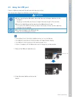
Page 73: ...cap when the USB port is not in use If corrosion of the USB terminal occurs due to the intrusion of water or other substance charging will not be possible Do not pull strongly on the USB port cap There is a risk of damage to the cap This USB port is only for USB compatible devices such as smartphones The USB port is rated for 5V 500mA and does not support rapid charging The USB port is only functi...

Page 74: ...72 Model Ci User Manual 4 Operating Procedures 3 Connect the USB cable to the USB port 4 When finished disconnect the USB cable and insert the protective cap back into the USB port Power button ...

Page 75: ...t There is a risk of bodily injury and or device damage Do not perform any disassembly adjustment or repair that are not explained in this manual If the customer performs such acts him herself there is the serious safety risk Consult with your distributor when adjusting the seat length or arm position Only a trained service technician can provide maintenance on the device Do not disassemble adjust...

Page 76: ...74 Model Ci User Manual 5 Assembly Adjustment and Disassembly Rear drive base Battery Storage basket ...

Page 77: ...a risk of unexpected accident CAUTION When assembling the device grasp only the handle parts that are explained in this manual and do not hold the device by any other areas There is a risk of injury caused when a hand become caught in the device When assembling check that the magnetic connectors are not dirty If a magnetic connector is dirty current may not flow through it and the power may not tu...

Page 78: ...ive base 2 Slowly tilt the rear drive base forward and connect thef front drive base and rear drive base When the two components are correctly connected a click sound is heard when the two components are currently connected 3 Check that the anti tip bar is lowered 5 2 2 Installing the storage basket Handle A Handle B Anti tip bar ...

Page 79: ...basket with the rear drive base 2 Rotate the storage basket and place the basket onto the front drive base 3 Fasten the velcro on the bottom of the storage basket to the front drive base Velcro fastener Front drive base Bottom of storage basket 5 2 3 Installing the seat assembly Hook ...

Page 80: ... rear drive base and the connection between the battery and rear drive base The magneticism of the magnetic connectors may have an adverse effect on electrical medical devices Do not touch the battery connectors allow them to become wet or bring any metal or other foreign objects close to them There is a risk of injury and of damage to the device or its parts CAUTION Do not press a sharp object ag...

Page 81: ...he seat cushion from the seat assembly 2 Grasp the arm rest and lift up the seat assembly 3 Fit the seat assembly straight into position while checking the seat post position from the view hole in the seat assembly Seat cushion Arm support View hole Photo viewing from above ...

Page 82: ...tment and Disassembly 4 Install the seat cushion onto the seat assembly 5 Lower the seat release lever The seat is fastened onto the seat post 6 Hang the storage basket hook onto the accessory bar Seat cushion Seat release lever Accessory bar ...

Page 83: ... Grasp the battery handle and align the battery with the s on the bottom of the mounting area The battery weighs 6 2 lbs 2 8 kg Be careful not to drop it when handling it There is a risk of injury or damage caused by the battery dropping 2 Press the top of the battery in to install it If the battery cannot not be installed even when pressing on it with some force check whether the battery lock is ...

Page 84: ...njury When moving the foot rest up and down be careful that your fingers do not become caught in the connection There is a risk of injury When moving the back support up or down in order to adjust the back support height or for other reason be careful that your fingers do not become caught in the bottom of the back support or the connection There is a risk of injury CAUTION When adjusting the devi...

Page 85: ...o remove it 2 While pulling on the arm length adjustment tab slide the arm up or down to adjust it to the desired length Release the arm length adjustment tab at one of the four labelled positions to lock the arm in place and a click sound is heard The arm length can be adjusted in 4 stages After adjustment is completed try to slide the arm up and down to confirm that it is locked in place and doe...

Page 86: ...stment There is a risk of electric shock and unexpected device operation Do not place a load on the directional controller assembly or scratch it with a sharp object There is a risk that the directional controller assembly may be damaged rendering the device inoperable Do not throw step on or otherwise subject the removed control pad or directional controller assembly to strong impact and do not i...

Page 87: ...act your distributor There is a risk of damage to the device that renders it inoperable 1 Remove the battery For the removal procedure refer to 5 4 1 Removing the battery 2 Remove the arm cover For the removal procedure refer to Step 1 in 5 3 1 Adjusting the arm length 3 Rotate the inside cover counterclockwise and remove it ...

Page 88: ...ving the control assemblies from the arm do not pull forcefully on it There is a risk of breaking the cable that is connected to it 5 Disconnect the connector 1 Rotate the connector base lock counterclockwise to loosen it The lock is released 2 Pull out the connector When disconnecting the connector do not pull forcefully on control assemblies There is a risk of breaking the cables 6 Rotate the ou...

Page 89: ...over on the opposite side box in the same way 9 Switch the location of control assemblies Insert the connector and rotate the base lock clockwise to lock it Rotate the lock until a click sound is heard 10 Install the control assemblies onto the arms 1 Slide the control assemblies onto the arm 2 Slide control assemblies downward When a click sound is heard and the white lever rises the box is faste...

Page 90: ...t in the cover 13 Install the battery and check that the rear tail light illuminates for several seconds For the installation procedure refer to 5 2 4 Installing the battery If the rear tail light flashes there may be a problem with the battery connectors Check the connectors again 14 Turn on the power and check that the device moves forward backward left and right without problems If an error app...

Page 91: ...arts Be sure to remove the battery before performing adjustment There is a risk of electric shock and unexpected device operation CAUTION When adjusting the seat height do not pull forcefully on the seat post There is a cable inside the seat post Pulling forcefully on the seat post may break the cable inside it Do not press a sharp object against or apply a load to the seatback cables located on t...

Page 92: ...r to 5 4 2 Removing the seat assembly 3 Use a hex wrench 8 and remove the seat post bolt 4 Move the seat post up or down and align with the hole that you want to adjust it to The seat height can be adjusted in 5 stages There is a cable inside the seat post Pulling forcefully on the seat post may pull and break the cable inside it Be careful not to forcefully pull on the seat post Bolt Seat post Ca...

Page 93: ...to the hole at the desired height and tighten it securely Tightening torque 25 Nm The seat post is fastened in place 6 Install the seat assembly For the installation procedure refer to 5 2 3 Installing the seat assembly 7 Install the battery For the installation procedure refer to 5 2 4 Installing the battery ...

Page 94: ... rear 2 Use a hex wrench 4 and loosen the 4 bolts It is not necessary to remove the bolts all the way 3 Move the back support up or down to adjust it 4 When it is at the desired height tighten the loosened bolts Tightening torque 10 Nm The back support is fastened in place 5 Install the back cushion Return the back cushion to its original position and fasten it with the velcro fastener ...

Page 95: ...le 1 Remove the seat cushion 2 Tilt the back support forward slightly 3 Lift up the adjustment block while turning it and adjust to the correct angle The back support can be adjusted in 3 stages 90 95 100 Adjust the left and right blocks to the same angle 4 Install the seat cushion Adjustment block ...

Page 96: ...Do not touch the battery conectors allow them to become wet or bring any metal or other foreign objects close to them There is a risk of injury and of damage to the device or its parts Be sure to remove the battery before performing disassembly There is a risk of electric shock and unexpected device operation In addition if the device is disassembled without the battery removed there is a risk tha...

Page 97: ... battery and turn the key to unlock the battery 3 Grasp the handle and pull it toward you to remove the battery Pull the handle toward you and lift up the battery to disconnect it from the projections at the bottom The battery weighs 6 2 lbs 2 8 kg Be careful not to drop it when removing it There is a risk of injury or damage caused by the battery dropping Keyhole Projections ...

Page 98: ...ly and rear drive base and the connection between the battery and rear drive base The magneticism of the magnetic connectors may have an adverse effect on electrical medical devices Do not sit on the controller knob place the removed seat upside down or apply an excessive load to the controller knob There is a risk that the controller knob may be damaged rendering the device inoperable CAUTION Do ...

Page 99: ... seat assembly toward you Use caution because if you place a knee on the foot rest or otherwise apply weight to it the device may tip over 3 Grasp the arm rests and lift the seat assembly straight up to remove it from the Rear drive base Lift up the seat assembly slowly so that it does not contact other parts 4 Set the removed seat assembly on the floor with the cushion side facing up Seat release...

Page 100: ...e storage basket 1 Remove all items that are in the storage basket 2 Lift up the storage basket and disconnect the velcro fastener that is on the bottom of the front drive base 3 Lift up the storage basket while rotating it toward you to disengage it from the rear drive base hook ...

Page 101: ...k between the front drive base and rear drive base 2 Grasp handle A and disengage handle B from the hook of the rear drive base Support the rear drive base with a hand while disconnecting so that the rear drive base does not fall over 3 Place the disassembled front drive base and rear drive base as shown in the photo at right Base release lever Handle A ...

Page 102: ...100 Model Ci User Manual 5 Assembly Adjustment and Disassembly ...

Page 103: ...ere is a risk of device malfunction Do not store the device or storage basket outdoors in a location exposed to direct sunlight or rain There is a risk that rain may cause a short circuit and that direct sunlight may cause deformation or deterioration of the device or storage basket Store them indoors or in another location under a roof When storing for a long period of time When storing for a lon...

Page 104: ... device as a seat in an automobile or other vehicle There is a risk of damage to the device causing an unexpected accident Do not lift up the device when there is a person on the device There is a risk of damage to the device causing an unexpected accident CAUTION When boarding an airplane notify the airline company in advance that you will be using a personal electric vehicle receive an explanati...

Page 105: ...nnectors are located at the connection between the seat assembly and rear drive base and the connection between the battery and rear drive base The magneticism of the magnetic connectors may have an adverse effect on electrical medical devices Do not touch the battery connectors allow them to become wet or bring any metal or other foreign objects close to them There is a risk of injury and of dama...

Page 106: ... on the end of the foot rest and the handle A Rear drive base WARNING Do not touch the battery connectors allow them to become wet or bring any metal or other foreign objects close to them There is a risk of injury and of damage to the device or its parts Carry by holding the handle on top of the main body and the anti tip bar Arm rest Handle A Foot rest handle Handle on top of main body Anti tip ...

Page 107: ...nfigure the device settings from the app The app s remote control functions also makes it possible to move the wheelchair aside after use or to move it to a narrow storage space The following is an explanation of how to download and install this app Downloading the app may incur data charges 1 From the home screen tap App Store The App Store appears 2 Tap Search The search window appears ...

Page 108: ...button changes to INSTALL 5 Tap INSTALL and enter your password Downloading begins When the display changes to OPEN the app can be opened and used For the app login ID and password refer to the last page of this manual Procedure for reissue of app password Reissue of the app password can be requested through WHILL Customer Support ...

Page 109: ...ng to keep the device clean If there is significant dirt on the exterior or wheels either wipe it away with a wet towel or wash it with water If the dirt is stubborn use a neutral detergent Avoid the use of petroleum based detergents Do not use a high pressure washer CAUTION Do not use paint thinner benzene or other organic solvents for cleaning and do not use a high pressure washer Doing so may r...

Page 110: ...on battery For the messages shown on the display refer to 9 Troubleshooting 1 Insert a flathead screwdriver into the hole in the case and remove the case Hole 2 Pull back the terminal and remove the old battery from the battery case 3 Pull back the terminal and install a new battery under the rib in the battery case 4 Install the case 1 Insert the tab into the hole 2 Press the opposite side of the...

Page 111: ...lling the Controller Knob If the controller knob comes off of the directional controller assembly follow the procedure below to reinstall it 1 Fit the controller knob in place 90 relative to the direction of forward travel 2 Rotate the controller knob clockwise by 90 ...

Page 112: ...t of the foot rest angle Adjustment of the seat length Adjustment of the arm position Replacement of the back support Installation of a lap belt The following components can be removed from the device and repaired individually Seat assembly Rear drive base Front drive base Charger provided device For details please contact your distributor or WHILL Customer Support WARNING Be sure to replace the a...

Page 113: ...ecycled in accordance with European Directive 2012 19 EC WEEE Directive In order to protect the environment when the device lifetime is reached have the device collected by the local recycling center Because the WEEE Directive does not apply to all countries in Europe follow the regulations in that country when disposing of the device 8 6 Disposal CAUTION When disposing of the device and its parts...

Page 114: ...112 Model Ci User Manual 8 Maintenance and Inspection ...

Page 115: ...roller was not in neutral position when the power was turned on Power back ON without touching the directional controler 03 Raise the red lever on the side of the device and turn the power on again The brakes was released Lock the brakes The charger was connected while the power was on or the device was turned on while charging Disconnect the charger The display shown at right appears Low battery ...

Page 116: ... to a location where the inclination angle is 10 or less This notification disappears after a certain length of time 5 minutes or more Drive slowly while being careful to avoid steep slopes Replace the smart key battery The smart key battery level is low Replace the smart key battery The error message number shown in the display appears together with a red vertical line If an error not in the abov...

Page 117: ...0 Cruising distance Maximum 10 miles 16 km Maximum load 253 lbs 115 kg Rear tail light LED lamp red Charging time 5 hours Service environment 15 to 40 C 5 to 104 F Pivot width 30 inches 760 mm Estimated service lifetime 5 years Noise produced by the device and level thereof Below 65dBA except audible warning device Battery Item Spec Battery type Lithium ion battery Nominal voltage 25 2 V Rated cap...

Page 118: ...thium ion battery Rated capacity of charged battery 5 hour rate 10040 mAh Environmental protection grade IPX4 Connector pin allocation Pin1 Pin2 Pin3 Detection Pin4 Non connected Type reference of the battery charger Off board battery charger Rated current of any user accessible protective fuses There are no user accessible fuses Name and address of the battery charger manufacturer WHILL Inc 285 O...

Page 119: ...driving 2 inches 50 mm Maximum forward speed 5 mph 6 km h Seat angle 6 Effective seat length 14 8 inches 375 mm 16 7 inches 425 mm 3 stages Effective seat width 16 inches 400 mm 18 inches 460 mm Ground height of seat front edge 17 5 inches 445 mm 20 7 inches 525 mm Back support angle 90 100 3 stages Back support height 29 1 inches 740 mm 37 inches 940 mm stepless Height from foot rest to seat asse...

Page 120: ...118 Model Ci User Manual 10 Specifications and Test Results ...

Page 121: ...l 83 Boarding 44 Brakes 55 Brake release levers 28 55 C Charge level 38 49 Charge level indicator 32 38 Charger 29 32 96 Charging 60 Charging procedures 33 Contact information 106 Control pad 27 72 D Dimensions 102 Directional controller assembly 26 53 Switching the left and right sides 72 Disassembly procedures 82 Storage basket 85 Battery 83 Display 27 98 Disposal 97 Driving 50 E Electromagnetic...

Page 122: ... brakes 55 RFI 16 S Safety precautions 6 Seat assembly 62 66 83 89 96 Adjusting the height 77 Seatback cables 66 Seat post 78 Seat release lever 27 68 Serial number 24 Smart key 29 58 Replacing the battery 94 Smartphone 60 91 Smartphone app 91 Speaker 27 Specifications 100 Speed select buttons 27 49 Stopping 53 Storage 87 Storage basket 27 57 63 65 85 T Test results 100 Transport 88 Troubleshootin...

Page 123: ...121 Model Ci User Manual About the Warranty About the Warranty Get warranty information from WHILL US Sales ...

Page 124: ...e distributor where this device was purchased will handle requests for repair maintenance and parts replacement To determine whether or not a loaner device is provided during servicing contact the distributor Distributor Manufacturer App login ID and password WHILL Inc ...

Reviews: