background image

5-7

Valco Cincinnati, Inc.

Section 5 - Operation

MC091 - VCX OT-120 FlexosealPro 2 - Corrugated

3.

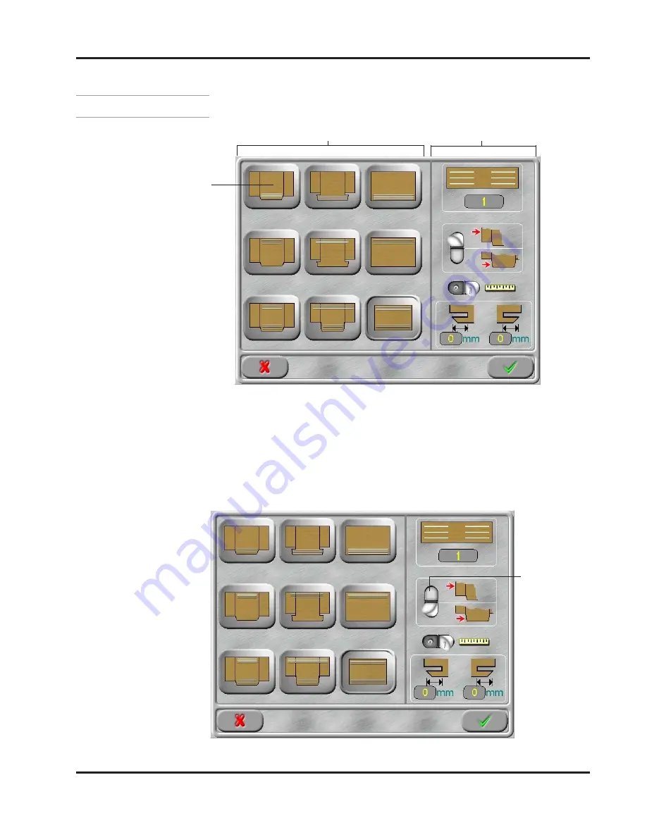
The additional option buttons on the Glue Mode Selection
Screen will be enabled or disabled depending on the mode
selected. For example, in the Glue Station 1 Standard Tab Mode,
all buttons except the Extended Tab Start/End Values can be
selected and changed.

2.

Choose a glue pattern. For example, choose Glue Station 1
Standard Tab.

Selecting a Glue Mode - Continued

Figure 5-10. Glue Mode Selection Screen

Edge Trigger
(scan) selected

Figure 5-9. Glue Mode Selection Screen

Glue Station 1-

Standard Tab

Additional Options

Glue Modes

Summary of Contents for VCX OT-120 FlexosealPro 2-Corrugated

Page 1: ...120 VCX OT 120 VCX OT 120 VCX OT 120 FlexosealPro 2 Corrugated FlexosealPro 2 Corrugated FlexosealPro 2 Corrugated FlexosealPro 2 Corrugated FlexosealPro 2 Corrugated Manual Number MC091 Release Date 3 2018 Version C008 ...

Page 2: ...Suite 490 Cincinnati OH 45246 Tel 513 874 6550 Fax 513 874 3612 Email sales valcomelton com Web http www valcocincinnatiinc com Valco Cincinnati Limited Valco Cincinnati Limited Valco Cincinnati Limited Valco Cincinnati Limited Valco Cincinnati Limited Hortonwood 32 Telford TFI 7YN England Tel 44 1952 677911 Fax 44 1952 677945 Email sales valco co uk Web http www valco co uk Valco Cincinnati GmbH ...

Page 3: ...following standards Safety Risk EMC Emissions EMC Immunity Place and Date Signature Valco Melton A division of Valco Cincinnati Incorporated 411 Circle Freeway Drive Cincinnati OH 45246 USA Valco Cincinnati Ltd Unit 7 8 Hortonwood 32 Telford TF1 7YN England VCX OT 120 Flexoseal 2 Corrugated 2006 42 EC 2006 95 EC 2004 108 EC EN60204 1 2006 EN13849 1 EN14121 1 2007 EN61000 6 4 2007 EN61000 4 2 EN610...

Page 4: ...upply Module 3 2 Terminal Port 3 4 Control Link Port 3 5 Encoder Connections Male Output 3 6 Encoder Connections Female Input 3 7 Pump Connection 3 7 Beacon Alarm Connection 3 8 Relay Feed Stop Connection 3 9 Relay Machine Stop Connection 3 9 Inspection Control Module ICM 3 10 RS 232 Port 3 13 Marking Valve Connection 3 13 Scanner Connection 3 14 Sensors 1 2 J Box Connections 3 15 Sensors 3 4 J Bo...

Page 5: ...for Preconfiguration 4 10 OT Configuration Setup 4 12 Glue Stations 4 16 List of Glue Stations Parameter 3100 0E 4 16 Machine Communication 4 16 Initialization Files Definitions 4 17 Section 5 Operation 5 1 Power Up Sequence 5 1 The Main Menu Screen 5 2 Entering a PIN 5 4 Selecting a Glue Mode 5 5 Multiple Pattern Gluing 5 9 Enter Tab and Glue Lengths 5 10 Configure the Glue Valves 5 11 Jog Stitch...

Page 6: ...otten Passwords 6 33 Lockout Configuration Access 6 37 Tipsealer Air Cylinder Timing Values 6 39 Upgrade Procedure 6 42 Part Number 6 47 Replacing the SD Memory Card in the OT 120 6 48 Backup Dialog 6 49 Restore Dialog 6 50 Section 7 part number list 7 1 How to Order Parts 7 1 VCX 4 Control Base 074xx042 7 2 PCM 4 Module w EPC VCX Control 074xx054 7 4 Standard OT 120 138xx018 7 6 Mounting Assembly...

Page 7: ...20 FlexosealPro 2 Corrugated Appendix A Monitor Commands A 1 PCM4 Monitor Commands A 1 ICM4 Monitor Commands A 2 Appendix B Diagnostics B 1 Encoder Diagnostics B 1 Scanner Diagnostics B 2 Appendix C Electrical Diagram C 1 Electric Wiring for VCX w Tipsealer C 1 ...

Page 8: ... used with 3 Valve Boardrunner systems is a modular integrated system for gluing control and quality assurance This manual provides the information necessary to setup maintain and troubleshoot the VCX Control system A parts list with options is also included Valco Cincinnati Inc recommends reading this manual before beginning to use the VCX Control system ...

Page 9: ...rnings draw special attention to anything that could injure or kill the reader Both Cautions and Warnings are placed before the step they apply to This symbol represents a Hot Surface Hot Surface Hot Surface Hot Surface Hot Surface This symbol represents a Puncture Risk Puncture Risk Puncture Risk Puncture Risk Puncture Risk It is usually used in regard to nozzle cleaning appliances and other shar...

Page 10: ...ect All Power Unplug Disconnect All Power Sources Sources Sources Sources Sources and to let them de energize before attempting any type of work or maintenance Remember that there can still be energy in equipment cords and wires even when unplugged disconnected This symbol indicates the need to Lock Out All Power Sources Lock Out All Power Sources Lock Out All Power Sources Lock Out All Power Sour...

Page 11: ...re there are regular inspections of equipment and safety devices Have regular safety drills and inspections supervised by the proper authorities Provide all required safety items first aid equipment and training The owner of the equipment is under obligation to make certain that all personnel who will handle install maintain operate fix and work around the equipment are qualified trained and up to...

Page 12: ...nt fuses and other power supplies Replace worn cords hoses etc immediately FAILURE TO OBSERVE WARNING MAY RESULT IN DEATH PERSONAL INJURY AND OR EQUIPMENT DAMAGE Warning Warning Warning Warning Warning Poor ventilation smoking and open flames can cause overheated hot melt to ignite Adequate ventilation must be provided Smoking should be prohibited in the immediate vicinity of the molten adhesive O...

Page 13: ...ay still be energized even if unplugged When making adjustments or performing checkout procedures stay clear of any moving mechanical parts and do not touch exposed electrical equipment or electrical connectors OTHERWISE DEATH OR PERSONAL INJURY COULD OCCUR Warning Warning Warning Warning Warning Disconnect disable all mechanical and or electrical devices that send activation signals to the gun s ...

Page 14: ...eviously mentioned this is not intended to be an exhaustive list follow all instructions and safety precautions for the specific type of equipment involved Warning Warning Warning Warning Warning Keep pump cover and electrical enclosures closed except during setup service and checkout procedures OTHERWISE DEATH OR PERSONAL INJURY COULD OCCUR Warning Warning Warning Warning Warning People with resp...

Page 15: ...t a source of clean cold water be provided near the hot melt work area 2 Cover the affected area with a clean wet compress and call the emergency medical response system such as 911 immediately 3 Watch for and treat the subject for signs of shock while waiting for professional help to arrive What to Do if Contact with Hot Adhesive Occurs If adhesive fumes are inhaled immediately follow these steps...

Page 16: ...process the surface of the adhesive will be exposed to air The mixture of polymer fumes and air can catch fire if the hot melt is overheated Warning Warning Warning Warning Warning Poor ventilation smoking and open flames can cause overheated hot melt to ignite Adequate ventilation must be provided Smoking should be prohibited in the immediate vicinity of the molten adhesive Open flames must be ke...

Page 17: ... Do not Do not Do not allow kinks or indentations in the hoses Do Do Do Do Do use a minimum bend radius of 10 inches for a 20 inch diameter coil hose Do not Do not Do not Do not Do not use unapproved hooks to hang hoses Do not Do not Do not Do not Do not wrap hoses over or around objects Do Do Do Do Do use a hose hanging kit P N 781xx827 Do not Do not Do not Do not Do not use the one handed one wr...

Page 18: ...ct with sharp edges or points Do Do Do Do Do wrap the hoses in approved padding P N 795xx549 if the hoses must be installed where they will come into contact with objects Do not Do not Do not Do not Do not use worn damaged or bent hoses Do Do Do Do Do inspect all hoses regularly for damage and or wear and replace damaged or worn hoses immediately Hose Safety Information Continued ...

Page 19: ...available in the base assembly for addidtional modules Inspection Control Modules ICM Figure 3 1 illustrates the VCX Control base with the Power Supply Module and Pattern Control Module PCM Notice that the Power Supply Module is always on the left side of the control Additional modules are added from left to right Always place the Tracking Control Module s if used in the slot s on the right Figure...

Page 20: ...lco Cincinnati Inc Section 3 Basic Features MC091 VCX OT 120 FlexosealPro 2 Corrugated Power Supply Module 16 17 N 230 115 VAC L1 F2 F1 F5 F4 F3 Out In 1 2 1 2 7 8 9 10 11 12 13 14 15 5 1 2 3 6a 4 6b 6c 18 19 ...

Page 21: ...s Switches Number Name 7 Terminal Port 8 Control Link Port 9 Encoder Out Connections 1 2 10 Encoder In Connections 1 2 11 Pump Connection 12 Beacon Alarm Connection 13 Relay Feed Stop Connection 14 Relay Machine Stop Connection 15 Grounding Stud 16 Power Cord Entry 17 Power On Off Switch 18 CAN Switch Power Supply Module Features Fuses Number Fuse Type Part No 5 Main Fuse F1 F2 6 3A 085xx221 6a Fu...

Page 22: ...erminal Port Terminal Port Terminal Port Terminal Port Terminal Port Power Supply Module Connector Pinouts Connector 7 Terminal Port Pin Description 1 CAN Low 2 CAN High 3 P Button 4 P Button 5 Remote Out 6 24V 7 24V 8 24V 9 OV 10 OV 11 OV 12 OV 13 OV 14 N C 15 N C Pinout Drawing for Connector 7 ...

Page 23: ...lexosealPro 2 Corrugated Control Link Port Control Link Port Control Link Port Control Link Port Control Link Port Connector 8 Control Link Port Pin Description 1 N C 2 CAN Low 3 CAN Ground 4 OV 5 N C 6 N C 7 CAN High 8 Remote Out 9 CAN 5V Pinout Drawing for Connector 8 ...

Page 24: ...ncoder Connections Encoder Connections Encoder Connections Male Output Male Output Male Output Male Output Male Output Connector 9 Encoder Connections Pin Description Color 1 Ground Black 2 A Signal Orange 3 24V 12V Red 4 B Signal Yellow 5 Z Signal Brown 6 Z Signal Violet 7 B Signal Blue 8 A Signal Green Pinout Drawing for Connector 9 ...

Page 25: ...nput Pump Connection Pump Connection Pump Connection Pump Connection Pump Connection Connector 10 Encoder Connections Pin Description Color 1 Ground Black 2 A Signal Orange 3 24V 12V Red 4 B Signal Yellow 5 Z Signal Brown 6 Z Signal Violet 7 B Signal Blue 8 A Signal Green Pinout Drawing for Connector 10 Connector 11 Pump Connection Pin Description Color 1 24VDC Brown 2 N C White 3 24VDC Blue 4 N C...

Page 26: ...con Alarm Connection Beacon Alarm Connection Beacon Alarm Connection Beacon Alarm Connection Beacon Alarm Connection Connector 12 Beacon Alarm Connection Pin Description Color 1 Ground Brown 2 Light Glue White 3 Light Jam Blue 4 Buzzer Black 5 Light LLD Shield Gray Pinout Drawing for Connector 12 ...

Page 27: ...onnection Relay Machine Stop Relay Machine Stop Relay Machine Stop Relay Machine Stop Relay Machine Stop Connection Connection Connection Connection Connection Connector 13 Relay Feed Stop Connection Pin Description Color 1 COM Brown 2 N C White 3 N O Blue Pinout Drawing for Connector 13 Connector 14 Relay Machine Stop Connection Pin Description Color 1 COM Brown 2 N C White 3 N O Blue Pinout Draw...

Page 28: ...3 10 Valco Cincinnati Inc Section 3 Basic Features MC091 VCX OT 120 FlexosealPro 2 Corrugated Inspection Control Module ICM X 1 3 2 4 5 9 6 7 8 Modules 1 4 10 11 12 15a 15b 10 12 13 14 ...

Page 29: ...or use in the Inspection Control Module These modules slide in as shown below The modules available are The modules available are The modules available are The modules available are The modules available are AS 601 151xx501 AS 301 151xx512 AS CGS 151xx460 Digital 151xx539 Microwave 151xx507 Sensor 4 Sensor 3 Sensor 2 Sensor 1 Inspection Control Module ICM Continued ...

Page 30: ...t a signal is not being received at the present time 3 CAN E Illuminates green when there is an error with communication 4 Good Product Detected 1 4 5 Bad Product Detected 1 4 6 Glue Level Sensor 1 4 7 Trigger 1 4 8 Marking Valve 1 2 9 Encoder 1 2 Inspection Control Module Features Connectors Number Name 10 RS 232 Port 11 Sensor Connection 1 4 12 Marking Valve Connection 13 Sensor Connection 1 2 1...

Page 31: ...ve Connection Marking Valve Connection Marking Valve Connection Marking Valve Connection Marking Valve Connection 1 5 6 9 Connector 10 RS 232 Port Pin Description 1 N C 2 RXD 3 TXD 4 N C 5 GND 6 N C 7 N C 8 N C 9 N C Pinout Drawing for Connector 10 Connector 12 Marking Valve Connection Pin Description Color 1 Coil Brown 2 Coil White 3 Purge Blue 4 Purge Black 5 PE Shield Grey Pinout Drawing for Co...

Page 32: ...V AN Signal 0 20mA AN Signal IN 1 NPN PNP 10V AN Signal White 2 Int Scanner NPN Int Scanner NPN Int Scanner PNP IN 3 NPN PNP N C Brown 3 12V 12V ST LED OUT 1 NPN PNP 12V Green 4 N C AN GND AN GND IN 2 NPN PNP N C Yellow 5 12V 24V 24V 24V 12V Grey 6 12V 12V N C OUT 2 NPN PNP 12V Pink 7 ERR ERR ERR IN 4 NPN PNP ERR Blue 8 GND GND GND GND GND Red Pinout Drawing for Connector 11 Type Sensor Adapter Mo...

Page 33: ...ignal description reference table Connector 11 Connector 13 Sensor Connections 1 2 Pin Description 1 Sensor 1 1 2 Sensor 1 2 3 Sensor 1 3 4 Sensor 1 4 5 Sensor 1 5 6 Sensor 1 8 7 N C 8 Sensor 2 1 9 Sensor 2 2 10 Sensor 2 3 11 Sensor 2 4 12 Sensor 2 5 13 Sensor 2 8 14 Sensor 1 1 15 Sensor 1 3 16 Sensor 1 6 17 Sensor 1 7 18 Sensor 1 8 19 N C 20 N C 21 Sensor 2 1 22 Sensor 2 3 23 Sensor 2 6 24 Sensor...

Page 34: ...ignal description reference table Connector 11 Connector 14 Sensor Connections 3 4 Pin Description 1 Sensor 3 1 2 Sensor 3 2 3 Sensor 3 3 4 Sensor 3 4 5 Sensor 3 5 6 Sensor 3 8 7 N C 8 Sensor 4 1 9 Sensor 4 2 10 Sensor 4 3 11 Sensor 4 4 12 Sensor 4 5 13 Sensor 4 8 14 Sensor 3 1 15 Sensor 3 3 16 Sensor 3 6 17 Sensor 3 7 18 Sensor 3 8 19 N C 20 N C 21 Sensor 4 1 22 Sensor 4 3 23 Sensor 4 6 24 Sensor...

Page 35: ...atures MC091 VCX OT 120 FlexosealPro 2 Corrugated Pattern Control Module PCM Tri Valve Version 074xx054 2 3 4 1 2 1 2 80V PCM 4 Exhaust Out In 2 24V S E 1 2 3 4 CAN 1 2 3 4 1 2 3 4 1 1a 1b 1c 1d 1f Fuse 10 11 12 13 14 2 4 3 5 6 7 8 9 1e 15 FUSES ...

Page 36: ...unication 4 Valve Power Supply LEDs 1 4 5 Valve Activation LEDs 1 4 6 Trigger Status LEDs 1 4 7 Input Status LEDs 1 4 1 Scanner 2 Ext Purge 3 Auto Manual 4 Feed Enable 8 EPC Status LEDs 1 2 9 Encoder Status LEDs 1 2 Connectors Number Name 10 Valve Connections 1 4 11 Manifold Connections 12 EPC 2 Connection 13 EPC 1 In Out Connections 14 Feed Enable Connection 15 Valve Connection Fuses Number Fuse ...

Page 37: ... Enable Connection Feed Enable Connection Feed Enable Connection Connector 12 EPC Connection Pin Description Color 1 24V Brown 2 OV Signal White 3 Ground Blue 4 0 20 mA Black 5 Shield Shield Gray Pinout Drawing for Connector 12 Can be switched to 0 10V via software Connector 14 Feed Enable Connection Pin Description Color 1 24V Brown 2 PNP White 3 Ground Blue 4 NPN Black 5 Shield Shield Gray Pinou...

Page 38: ...Pink 8 Valve 4 2 Red 9 Purge 1 Black 10 Purge 2 Orange 11 PE Tan 12 Valve 2 2 Violet Pinout Drawing for Connector 10 Valve Connection Valve Connection Valve Connection Valve Connection Valve Connection Connector 15 Valve Connections Pin Description Color 1 Coil Brown 2 Coil White 3 Purge Blue 4 Purge Black 5 PE Shield Green Yellow Pinout Drawing for Connector 10 Valve Connections 1 4 Valve Connect...

Page 39: ...lor 1 24V White 2 Scanner1 PNP Brown 3 Ground Green 4 Scanner1 NPN Yellow 5 Ext Purge Gray 6 Auto Man Pink 7 Valve 1 Blue 8 Valve Ground Red 9 Valve 2 Orange 10 Valve Ground Tan 11 Valve 3 4 Black 12 Valve Ground Violet Pinout Drawing for Connector 11 Manifold Connections Manifold Connections Manifold Connections Manifold Connections Manifold Connections ...

Page 40: ...T 120 FlexosealPro 2 Corrugated Pattern Control Module PCM Standard 074xx043 10 11 12 13 13 12 14 15 The bottom of the module may vary depending on the options and the style of the module Two examples are illustrated at right 16a 16b 16c 16d 16e 7 1 2 4 3 5 6 8 9 ...

Page 41: ...4 Valve Power Supply LEDs 1 4 5 Valve Activation LEDs 1 4 6 Trigger Status LEDs 1 4 7 Scanner Status LEDs 1 4 8 EPC Status LEDs 1 2 9 Encoder Status LEDs 1 2 Pattern Control Module Features Connectors Number Name 1 Diagnostic Port 10 Valve Connections 1 4 11 Scanner Connections 1 4 12 EPC 2 Connection 13 EPC 1 In Out Connections 14 Scanner Junction Box E Box Port 15 Valve Junction Box E Box Port P...

Page 42: ...canner Connections Scanner Connections Scanner Connections Scanner Connections Scanner Connections Connector 10 Valve Connections Pin Description Color 1 Coil Brown 2 Coil White 3 Purge Blue 4 Purge Black 5 PE Shield Green Yellow Pinout Drawing for Connector 10 Connector 11 Trigger Scanner Connections Pin Description Color 1 24V Brown 2 PNP White 3 Ground Blue 4 NPN Black 5 Shield Shield Grey Pino...

Page 43: ...xosealPro 2 Corrugated EPC 2 Connection EPC 2 Connection EPC 2 Connection EPC 2 Connection EPC 2 Connection Connector 12 EPC 2 Connection Pin Description Color 1 24V Brown 2 OV Signal White 3 Ground Blue 4 0 20 mA Black 5 Shield Shield Grey Pinout Drawing for Connector 12 ...

Page 44: ...x E Scanner Junction Box E Scanner Junction Box E Box Port Box Port Box Port Box Port Box Port Connector 14 Scanner Junction Box Port Pin Description 1 24V 2 Scanner 1 PNP 3 Scanner 1 NPN 4 Scanner 2 PNP 5 Scanner 2 NPN 6 Scanner 3 PNP 7 Scanner 3 NPN 8 Scanner 4 PNP 9 Scanner 4 NPN 10 N C 11 N C 12 N C 13 N C 14 N C 15 Ground Pinout Drawing for Connector 14 ...

Page 45: ...scription 1 Valve 1 Coil 2 N C 3 N C 4 Valve 1 Coil 5 Valve 2 Coil 6 Valve 2 Purge 7 Valve 2 Purge 8 Valve 2 Coil 9 Valve 4 Coil 10 N C 11 N C 12 Valve 4 Coil 13 Valve 3 Coil 14 Valve 3 Purge 15 Valve 3 Purge 16 Valve 3 Coil 17 N C 18 N C 19 N C 20 Valve 1 Coil 21 Valve 1 Purge 22 Valve 1 Purge 23 Valve 1 Coil 24 Valve 2 Coil 25 Valve 2 Coil 26 N C 27 N C 28 Valve 4 Coil 29 Valve 4 Purge 30 Valve ...

Page 46: ...3 28 Valco Cincinnati Inc Section 3 Basic Features MC091 VCX OT 120 FlexosealPro 2 Corrugated Pinout Drawing for Connector 15 ValveJunction Box E Box Port Continued ...

Page 47: ...3 29 Valco Cincinnati Inc Section 3 Basic Features MC091 VCX OT 120 FlexosealPro 2 Corrugated OT 120 Touchscreen 1 2 3 4 7 8 9 10 ...

Page 48: ...s LEDs Number Name 1 Consecutive Faults LED Illuminates when the programmed maximum number of consecutive faults is reached 3 Power On LED Buttons Number Name 2 Clear Faults Button 4 Power On Off Button Clear Faults Button is available in MCU Mode Connectors Number Name 7 COM Port 8 CAN Port 9 Power Control Port 10 Machine Communication ...

Page 49: ... VCX OT 120 FlexosealPro 2 Corrugated Top Switch Function Label OT Cable OT Cable 2m OT Cable 2m OT Cable 2m OT Cable 2m OT Cable 2m 029xx331 UNIT MCU VCX CAN 2 120 OHM OFF ON CAN 1 120 OHM OFF ON BACKL AUTO ON BRIGHTN AUTO FULL OT 120 Touchscreen Continued ...

Page 50: ...Cincinnati Inc Section 3 Basic Features MC091 VCX OT 120 FlexosealPro 2 Corrugated Mounting Bracket for OT 120 Control The mounting bracket for the OT 120 allows the operator to swivel the control for best viewing ...

Page 51: ...ce the cover Figure 4 1 Remove the VCX Control Cover Latch Latch Cover Cup Handle The Power Supply Module is always on the left side of the VCX Control Additional modules are added from left to right Always place the Tracking Control Module s in the slot s on the right Module choices include Pattern Control Modules PCM Inspection Control Modules ICM Tracking Control Modules with Ejector TCM E and ...

Page 52: ...t apply excessive force and do not use tools to seat the module Damage to the equipment may result 3 Slide the module into the VCX Control base as shown in Figure 4 2 Make sure the module slides in easily Pay attention to the connector and make sure the locator pin matches up with the mating connector Add Modules 4 Secure the module to the base rails with the screws located on both sides of the mo...

Page 53: ...e module 3 Loosen the screws that secure the module to the base rails of the VCX Control base see Figure 4 2 4 Slide the module out of the VCX Control base see Figure 4 2 5 Replace the cover on the VCX Control as described in this section 6 Reconnect the power cord and follow the powering up sequence VCX Specifications DIMENSIONS AND WEIGHT SIZE Width 19 482 6mm Height 12 304 8mm Depth 9 5 241 3mm...

Page 54: ...ayout 3 Valve Non Contact Boardrunner w VCX Exhaust Out In Out I n 1 2 1 2 V a l c o C i n c i n n a t i I n c 4 1 1 C i r c l e F r e e w a y D r i v e C i n c i n n a t i O H 4 5 2 4 6 5 1 3 8 7 4 6 5 5 0 155XX304 REV __ _ VD D 1 000 OT 120 138XX007 Figure 4 3a System Layout 1 3 8 X X 0 1 8 ...

Page 55: ...1 VCX OT 120 FlexosealPro 2 Corrugated System Layout 3 Valve Contact Boardrunner w VCX O u t In 1 2 1 2 I OI OI 1 2 3 4 2 Ex h aust Out In 1 2 3 4 Exhau s t In 2 Exhau s t 1 2 3 4 1 5 5 X X 3 0 4 R E V _ _ _ V D D 1 0 0 0 Figure 4 3b System Layout ...

Page 56: ...4 6 Valco Cincinnati Inc Section 4 Setup MC091 VCX OT 120 FlexosealPro 2 Corrugated Bracket Mounting Pattern VCX Control Mounting pattern is enlarged to show detail Figure 4 4 VCX Control ...

Page 57: ...4 7 Valco Cincinnati Inc Section 4 Setup MC091 VCX OT 120 FlexosealPro 2 Corrugated Pump Bracket Balancing Regulator Figure 4 5 Pump Bracket Figure 4 6 Balancing Regulator ...

Page 58: ...URY AND OR EQUIPMENT DAMAGE 1 Disconnect all power to all units controls 2 Determine the control that will be called VCX 1 3 Remove the covers from both VCX Controls see Figure 4 1 4 Verify that the Control Selector Switch on VCX 1 is set to 1 see Figure 4 7 CAREFULLY reach under the cover plate to reach the switch with your fingers see Figure 4 3 Figure 4 7 Control Selector Switch on the VCX Cont...

Page 59: ...both VCX Controls see Figure 4 1 7 Connect the cables on the VCX 1 the VCX 2 and the OT 120 Unit as shown in Figure 4 8 8 Reconnect the power 9 Perform the power up sequence Linking Two VCX Controls Continued Figure 4 8 Connecting the Cables The encoders can be linked together as shown above Out In 1 Out In VCX 1 VCX 2 Control Link Cable CAN Resistor Off CAN Resistor On ...

Page 60: ...nt application is needed click the locked Configuration Button located in the bottom left hand corner of the terminal screen A numeric keypad will appear Figure 4 11 Figure 4 9 OT 120 Application Select Figure 4 10 OT 120 Flexoseal Pro 2 Example The Screen may appear different depending on your application Scroll List of Available Options The Screen should start up with this image unless it has be...

Page 61: ...e is needed Figure 4 11 Keypad 3 After entering the password the Configuration Button will be unlocked Figure 4 12 Configuration Button Unlocked 4 Click the power button in the lower right corner 5 After the application closes click on the VLaunch shortcut 6 From the VLaunch screen Figure 4 13 scroll to and select the appropriate application from the list and make sure Do not show this message aga...

Page 62: ...ro 2 Corrugated Checking for Preconfiguration Continued Figure 4 13 OT 120 Application Selection OT Configuration Setup 1 After the application loads completely click the locked Configuration Button A numeric keypad will appear Figure 4 14 OT 120 Flexoseal Pro 2 Example ...

Page 63: ... FlexosealPro 2 Corrugated OT Configuration Setup Continued 2 On the keypad Figure 7 enter the pin 123 and press the Confirmation Button Figure 4 15 Keypad 3 In the Settings Menu Figure 4 16 click on the Restore Button Figure 4 16 Settings Menu Restore Button ...

Page 64: ...om the configuration menu Figure 4 18 select the appropriate configuration Figure 4 18 Configurations Menu 6 After selecting the configuration and clicking the Confirmation Button the terminal will shut down On boot up the terminal should automatically start up in the correct application This is the preferred method for setting the overall configurations An older method is expalined below for comp...

Page 65: ...ons Menu 1 From the General Settings Menu click on the Access Configuration Files Button A Configuration Files menu will open Access Configuration Files Button 2 In the Configuration Files menu change the Machine Communication codes as needed Refer to the lists under Machine Communication below for the code descriptions Figure 4 19 Configurations Files menu ...

Page 66: ...Runner FLP 4 8 Separated Valve NC Machine Communication In section MIF Parameter set the parameter Mode to the following 0 No external interface 1 Martin interface TCP IP 5 EMBA interface 9600 8 N 1 6 ASCII interface 9600 8 N 1 8 Extended ASCII interface 9600 8 N 1 9 MWU interface 9600 8 N 1 10 Martin interface inch mode TCP IP 11 MHI interface 9600 8 N 1 12 MHI V2 Interface 9600 8 N 1 13 MHI V2 I...

Page 67: ... Copied Valve Defaults VAR U16 RW 0 Valve Default Parameters will be copied on next power on 1 No action 0 0 1 A Pulse Purge Activation VAR U16 RW Number of Pulses at beginning of purge cycle 0 0 50 B TipSealer Status VAR U16 RO TipSealer Status 0 0 255 C Tipsealer Output Manual VAR U16 RW This output is active when the control is in the MANUAL mode 0 No Output 1 Glue Fault Light Blue 2 Jam Fault ...

Page 68: ...evision of software that is installed on the OT 120 The power up sequence is as follows 1 Press the Power On Button on the bottom left of the OT 120 see Figure 5 1 Power Up Sequence 2 Plug in the VCX 3 Flip the power switch on the back of the VCX Power Supply Module to the On position see Figure 5 2 Figure 5 1 OT 120 Touchscreen Figure 5 2 VCX Power Supply Module Power Switch Power Supply Module S...

Page 69: ...The Main Menu Screen Figure 5 4 Main Menu Screen Machine Speed Products Hour Machine Speed Meters or Feet minute Encoder Setup Button Pressure Setup Button Current Glue Mode picture Current Faults Current Pressure Valve Setup Button Exit Button General Setup Button Valve Number Current Time and Date Carton Score to Score Length Jam Detection Setup Button Good Products Job Bad Products Job Delay Be...

Page 70: ...mation Displays the current glue valve selected as a number value under the picture of the valve Valve Number Displays current glue valve selected General Setup Button Setup systemparameters Password protected levels define access permissions Inspection Sensor Setup Button Setup inspection tolerances such as glue volume and glue position Encoder Setup Button Setup the encoder pulse information and...

Page 71: ... enter a PIN do the following 1 Press the Locked General Setup Button with the stylus A keypad will appear asking for your PIN 3 PIN Entered PIN Level Figure 5 6 PIN level on the General Setup Button Locked Icon Unlocked Icon Caution Caution Caution Caution Caution Always use the stylus to press and select buttons on the OT 120 Touchscreen Otherwise damage to the unit can occur 2 Enter your PIN on...

Page 72: ... in the picture with the stylus The Glue Mode Selection Screen appears Selecting a Glue Mode Figure 5 8 Glue Mode Selection Screen Figure 5 7 Main Menu Screen Glue Station 1 Standard Tab Glue Station 2 No Tab Glue Stations 1 2 No Tab Edge Trigger scan Auto Glue ON OFF Extended Tab Start End Confirmation Button Cancel Button Tab Trigger scan Number of Patterns Press here Press here ...

Page 73: ...tab pattern Number of Patterns Number of Patterns up to four Edge Trigger Tab Trigger Either the edge or the tab will trigger the sensor depending on the setting Auto Glue ON OFF Switch between Auto Glue ON setting and Manual Glue OFF setting Extended Tab Start End Adjust the length of the start tab and the end tab for extended tab settings Confirmation Button Press to enter the new settings No se...

Page 74: ...selected For example in the Glue Station 1 Standard Tab Mode all buttons except the Extended Tab Start End Values can be selected and changed 2 Choose a glue pattern For example choose Glue Station 1 Standard Tab Selecting a Glue Mode Continued Figure 5 10 Glue Mode Selection Screen Edge Trigger scan selected Figure 5 9 Glue Mode Selection Screen Glue Station 1 Standard Tab Additional Options Glue...

Page 75: ...tion Button Selecting a Glue Mode Continued 5 After a Mode Change the Main Menu Screen may have different features and look slightly different The example above shows the Leading Edge to Tab Measurement that is not shown when the mode is set on Tab Trigger Scan Figure 5 11 Main Menu Screen After Mode Change Distance from Leading Edge to Tab Edge Trigger Scan On ...

Page 76: ...ated Multiple Pattern Gluing The machine may be set for multiple pattern gluing 1 On the Glue Mode Selection Screen press the Glue Station 2 button Pressing this button automatically sets the gluing mode to three 3 patterns Figure 5 12 Glue Mode Selection Screen Glue Station 2 button ...

Page 77: ...pear Enter the desired value and confirm Continue until all values are set for the job Some values are automatically calculated by the unit Enter Tab and Glue Lengths Delay Before Gluing Length Value Glue Line Length Value Figure 5 13 Main Menu Screen Figure 5 14 Numeric Keypad Increase value by 10 Decrease value by 10 Increase value by 1 Decrease value by 1 Cancel Confirm Backspace Delay After Gl...

Page 78: ...n Setup Button The Valve Configuration Screen will appear Configure the Glue Valves Figure 5 15 Main Menu Screen Figure 5 16 Valve Configuration Screen Valve Setup Button Confirmation Button Valve Purge Button Valve Number Purge All Button Valve On Off Incremental Glue Line Length Adjustment affects all lines Jog Stitch Configuration Button Top Down Bottom Up Switch Glue Station Setup Button ...

Page 79: ...lve Setup Button on the Valve Configuration Screen The Valve Setup Screen appears Configure the Glue Valves Continued Figure 5 17 Valve Setup Screen Minimum Activation Time Tmin Valve Type Distance from Valve to Scanner mm or inches Confirmation Button Cancel Button Minimum Speed Threshold Vmin Off Compensation Time Toff On Compensation Time Ton Correction Factor CF Scanner Number Valve Number Scr...

Page 80: ...ted and it begins to apply glue Correction Factor For right angle machines or 2 machines running at different speeds The correction factor allows for synchronization Confirmation Button Press to enter the new settings No settings or values are entered until this is pressed Cancel Button Cancel the new settings and return to the previous settings Use before pressing the Confirmation Button CAUTION ...

Page 81: ...pense glue Length between glue dot patterns A length that will be unglued between dot patterns of adhesive Length of glue dot patterns The length of the glue dot patterns Minimum Machine Speed for jogging This is the minimum machine speed at which the adhesive will be applied in a jogging pattern Confirmation Button Press to enter the new settings No settings or values are entered until this is pr...

Page 82: ...al application of long lines of glue It allows different input possibility of bead length and gap length Intermittent gluing is also possible The control will then take into account that each pattern ends with applied glue not with a gap It can cause the gap to deviate slightly from the entered value Jogging Mode Jogging Mode Jogging Mode Jogging Mode Jogging Mode Jogging mode is used for extremel...

Page 83: ...e Pressure Curve Display shows the pressure status To use the Pressure Menu Button do the following 1 Press the Pressure Menu Button on the Main Menu Screen The Pressure Menu opens Figure 5 20 Pressure Menu Screen Pressure Curve Decrease Current Pressure Current Valve Pressure Machine Stop Idle Pressure Pressure Transducer Configuration Button Increase Current Pressure Figure 5 19 Main Menu Screen...

Page 84: ...set to this pressure Use to keep adhesive ready to apply but not dispensing during machine stops Press for numerical keypad to edit Pressure Transducer Setup Dialog Pressing a Pressure Transducer Configuration Button on the Pressure Menu Screen opens the Pressure Transducer Setup Dialog for the selected pressure transducer In this dialog the number of points on the pressure curve can be adjusted T...

Page 85: ...tion of the pressure curve for the transducer Current Pressure Displays the current pressure Number of Points on the Pressure Curve Displays the number of points in the pressure curve Press for a numerical keypad to edit Machine Stop Idle Pressure When the machine stops the valve will automatically be set to this pressure Use this feature to keep adhesive ready to apply but not dispensing during m...

Page 86: ...tup Screen appears Encoder Setup 2 On the Encoder Setup Screen press the Repeat Length Value and or the Encoder Pulse Value to change a value When the keypad appears enter the desired value and press the Confirmation Button on the keypad Figure 5 22 Main Menu Screen Confirmation Button Cancellation Button Encoder Pulse Value Repeat Length Value Figure 5 23 Encoder Setup Screen Encoder Setup Button...

Page 87: ...he control to determine the speed of the parent machine You can use either a wheel driven VDD encoder and a measuring wheel or a hollow shaft encoder For optimal results use a VDD 1000 encoder for one of the following resolutions a 10 inch wheel 100 pulses inch a 250mm wheel 4 pulses mm Confirmation Button Press to enter the new settings No settings or values are entered until this is pressed Canc...

Page 88: ...tion Menu Dialog Figure 5 25 Jam Detection Menu Figure 5 24 Jam Detection Menu Button Dimension Length Individual Scanner Length Settings Fault Description Summary Bar Products per Hour Machine Speed Date and Time Repeat Dimension Length Apply Button Auto Stop Machine On Off Jam Detection Relay Jam Detection Speed Threshold Setting Alarm On Off Scanner On Off Switch Jam Detection Menu Button ...

Page 89: ...he machine stop signal will remain active after an active scanner detects a jam and the machine is stopped NOTE This feature will only work if the Auto Stop Machine On Off Switch is On Jam Detection Speed Threshold Setting The active scanners will not scan for jams until the machine is running at or above this speed The speed is measured in meters per minute or feet per minute Scanner On Off Switc...

Page 90: ...t tolerances Press the tolerance you want to change and a keypad will appear Enter the desired tolerance and press the Confirmation Button on the keypad to return to the Inspection Sensor Configuration Screen Figure 5 27 Inspection Sensor Configuration Screen Figure 5 26 Main Menu Screen Measured Glue Position Tolerance Modes Inspection Enable Target Glue Position Setup Menu Diagnostics Tolerance ...

Page 91: ...sured glue position Volume Enable On Off Switch Turns the Glue Volume Inspection on or off The sensor will not inspect the glue volume if this switch is off Volume Tolerance The inspection tolerance for the amount of glue on the product not available if the Glue Volume Inspection Switch is off Changes with the tolerance level Inspection Enable On Off Switch Switches the inspection sensor off and o...

Page 92: ...our job Make sure the correct scanner is selected assigned scanner or an internal scanner Press the Confirmation Button to save your settings The Inspection Sensor Configuration Screen appears Figure 5 29 Sensor Setup Screen Figure 5 28 Inspection Sensor Configuration Screen Trigger currently non selectable Scan Sensor Distance Glue Fault Buzzer Enable Glue Fault Light Enable Consecutive Faults Nu...

Page 93: ...s a later end and a negative number forces an earlier end Min Glue Length The minimum length of glue the sensor will be allowed to detect Min Gap Length The minimum gap without glue the sensor will be allowed to detect Gaps smaller than this will appear as glue Threshold Used to influence the inspection to look for glue at percentage levels of the sensors output signal A higher threshold percentag...

Page 94: ... the Main Menu Screen press the Exit Button A Confirmation Screen will appear 2 On the Confirmation Screen press the Cancel Button to cancel the exit and go back to the previous screen or press the Confirmation Button to exit the FlexosealPRO program Figure 5 30 Main Menu Screen Figure 5 31 Exit FlexosealPRO Confirmation Screen Cancel Button Confirmation Button Exit Button ...

Page 95: ...he VCX Power Supply Module to the Off position see Figure 5 29 Exit and Shutdown Continued 3 After the screen goes blank press the red On Off Button on the OT 120 see Figure 5 32 Figure 5 32 OT 120 Touchscreen Figure 5 33 VCX Power Supply Module Power Switch Power Supply Module Slots for Modules Power On Off Switch ON OFF Button ...

Page 96: ...ings for the selected sensor do the following 1 On the Main Menu Screen press the Inspection Sensor Setup Button The Inspection Sensor Configuration Screen appears Sensor Diagnostics Figure 6 2 Inspection Sensor Configuration Screen Figure 6 1 Main Menu Screen Diagnostic Button Inspection Sensor Button 2 On the Inspection Sensor Configuration Screen press the Diagnostic Button The Diagnostic Scree...

Page 97: ...lected sensor as follows 4 When you are done press the Confirmation Button on the Sensor Diagnostics Screen shown above The Inspection Sensor Configuration Screen appears Press the Confirmation Button on the Inspection Sensor Configuration Screen to return to the Main Menu Screen Figure 6 3 Sensor Diagnostics Screen Sensor Number Current Sensor Readout Readout for board without glue Confirmation B...

Page 98: ...o the following 1 On the Main Menu Screen press the Inspection Sensor Setup Button The Inspection Sensor Configuration Screen appears 2 On the Inspection Sensor Configuration Screen press the Tolerance Setup Button The Tolerance Setup Screen is displayed Figure 6 4 Main Menu Screen Figure 6 5 Inspection Sensor Configuration Screen Tolerance Setup Button Inspection Sensor Button ...

Page 99: ...e line start the glue line end the gaps between the glue lines and the volume Just press on a tolerance value and a keypad will appear 4 When the keypad appears enter the desired value and press the keypad Confirmation Button Continue this same process with each value until all changes are made Confirmation Button Cancel Button Confirmation Button Start Tolerance End Tolerance Gap Tolerance Tolera...

Page 100: ...onfirmation Button Then set the inspection sensor to use the small medium or large tolerances Press the corresponding tolerance picture and the values automatically change to the programmed values Press the Confirmation button to return to the Main Menu Screen Figure 6 8 Inspection Sensor Configuration Screen Tolerance Level Large Tolerance Level Small Tolerance Level Medium Confirmation Button ...

Page 101: ...he Inspection Sensor Setup Button The Inspection Sensor Configuration Screen appears 2 On the Inspection Sensor Configuration Screen make sure the Volume Inspection switch is ON and the Inspection Sensor Switch is ON Figure 6 9 Main Menu Screen The recommended default setting for the Volume Inspector Switch is OFF Turn it ON only when performing the system Learn Glue Volume procedure Figure 6 10 I...

Page 102: ...olume Button The Learn Volume Screen is displayed 4 When the Learn Volume Screen appears follow the directions on the screen Learn Volume Procedure Continued Figure 6 11 Inspection Sensor Configuration Screen Figure 6 12 Learn Volume Screen Learn Volume Button Start Learning Button Start machine with gluing Make sure glue volume is sufficient Press the START button ...

Page 103: ...rocessing the FlexosealPRO System will display one of the following messages To cancel the request press the Cancel button Message Displayed Information Learn Impossible The system cannot learn the machine may not be running or the Volume Inspection switch may be off Learn in Process The system is processing the glue volume information please wait Learn Successful The system has successfully learn...

Page 104: ...tware applications a Device Status Information Screen is available To access this feature do the following 1 On the Main Menu Screen press the General Setup Button The General Setup Screen appears 2 On the General Setup Screen press the Access Parameters Button The CAN Device Configuration Screen appears Figure 6 14 Main Menu Screen Figure 6 15 General Setup Screen General Setup Button Access Para...

Page 105: ...guration Screen This screen is explained in detail later in this section under Access Parameters 4 The Device Status Information Screen will appear 5 When done press the Confirmation Button on each screen until the Main Menu Screen appears Figure 6 16 CAN Device Configuration Screen Figure 6 17 Device Status Information Screen Confirmation Button Version Information MCP 12 Device Status Informatio...

Page 106: ... FlexosealPro 2 Corrugated Configure the Language To change the language of operation do the following 1 From the Main Menu Screen press the General Setup Button The General Setup Screen appears Figure 6 18 Main Menu Screen Figure 6 19 General Setup Screen General Setup Button ...

Page 107: ...ne of two methods Method 1 On the General Setup Screen scroll through the languages with the up and down arrow keys until the desired language is highlighted and then press the Home Button to return to the Main Screen Configure the Language Continued Figure 6 20 General Setup Screen Scroll with arrows Home Button ...

Page 108: ...n choose by pressing your selection and then press the Home Button to return to the Main Screen Configure the Language Continued 3 After finishing press the Home Button on the General Configuration Screen to return to the Main Menu Screen Figure 6 22 List of Languages Screen Figure 6 21 General Setup Screen Confirmation Button Press selection to highlight Scroll Buttons Home Button Press on the la...

Page 109: ...e To configure the time zone do the following 1 From the Main Menu Screen press the General Setup Button The General Setup Screen appears 2 On the General Setup Screen press the time zone A list of time zones will appear Figure 6 23 Main Menu Screen Figure 6 24 General Setup Screen General Setup Button Press on the time zone ...

Page 110: ...ht it Then press the Confirmation Button to return to the General Setup Screen 5 After finishing press the Home Button on the General Configuration Screen to return to the Main Menu Screen 4 Press the Set Button This must be done or your changes will not take effect Figure 6 25 List of Time Zones Screen Figure 6 26 General Setup Screen Confirmation Button Scroll Buttons Press on the desired time z...

Page 111: ...d format the date and time do the following 1 From the Main Menu Screen press the General Setup Button The General Setup Screen appears 2 On the General Setup Screen press the time and date value you wish to change A keypad will appear Figure 6 27 Main Menu Screen Figure 6 28 General Setup Screen General Setup Button Press on the values to change ...

Page 112: ...alue and press the keypad Confirmation Button Continue this same process with each value until all changes are made Change and Format the Time Date Continued 4 Press the Set Button This must be done or your changes will not take effect Figure 6 30 General Setup Screen Figure 6 29 Keypad Confirmation Button Up Down by One Up Down by Ten Set Button ...

Page 113: ...OT 120 FlexosealPro 2 Corrugated 5 When done choose the format of the display with the Date Format Switch Then press the Home Button to return to the Main Menu Screen Change and Format the Time Date Continued Figure 6 31 General Setup Screen HomeButton Date Format Switch ...

Page 114: ...meters do the following 1 From the Main Menu Screen press the General Setup Button The General Setup Screen appears 2 On the General Setup Screen press the Access Parameters Button The CAN Device Configuration Screen will appear Figure 6 32 Main Menu Screen Figure 6 33 General Setup Screen General Setup Button Access Parameters Button ...

Page 115: ...ccess the parameters Method 1 Enter an MCP parameter number in the Edit Field The other fields will be filled out with the applicable data to this specific parameter Access Parameters Continued Enter two new numbers in the Dual Edit Fields Method 2 Figure 6 34 CAN Device Configuration Screen Parameter Number Edit Field Figure 6 35 CAN Device Configuration Screen Dual Edit Fields ...

Page 116: ... Parameter Values To print capture the parameter values do the following 1 Connect a computer or a printer to the COM port on the MCP 12 Unit Each module has its own COM port 2 On the CAN Device Configuration Screen press the COM Port Button Press the Confirmation Button to return to the Main Menu Screen Figure 6 36 Model MCP 12 4 Control Unit Connection Module PCM 4 Diagnostic Printer COM Port 24...

Page 117: ...g 1 From the Main Menu Screen press the General Setup Button The General Setup Screen appears Password access can be customized See the topic Access General Configuration Files in this Section for more information 2 On the General Setup Screen press the Access Password Files Button Figure 6 38 Main Menu Screen Figure 6 39 General Setup Screen Access Password Files Button General Setup Button ...

Page 118: ...20 FlexosealPro 2 Corrugated 3 The Password Configuration Screen will appear Access Password Configuration Files Continued Figure 6 40 Password Configuration Setup Screen Input Panel Level 1 Password XXXXX Level 2 Password XXXXX Level 3 Password XXXXX Level 4 Password XXXXX ...

Page 119: ...ng Warning Warning Use ONLY NUMBERS for the password The system only uses passwords in all number form Figure 6 42 Input Panel Keyboard 4 Use the stylus to highlight the object you wish to change Use the Input Panel like a keyboard to enter data For example Highlight password with stylus Figure 6 41 Password Configuration Setup Screen Enter Key Level 1 Password XXXXX Level 2 Password XXXXX Level 3...

Page 120: ...eneral Setup Screen appears Access Password Configuration Files Continued 6 On the General Setup Screen press the Home Button to return to the Main Menu Screen Figure 6 43 Password Configuration Setup Screen Confirmation Button Level 1 Password XXXXX Level 2 Password XXXXX Level 3 Password XXXXX Level 4 Password XXXXX Figure 6 44 General Setup Screen Home Button ...

Page 121: ...rom English to your preferred language are not what you would like you can change the translation files To change the translation files do the following 1 From the Main Menu Screen press the General Setup Button The General Setup Screen appears 2 On the General Setup Screen press the Access Language Translation Files Button Figure 6 45 Main Menu Screen Figure 6 46 General Setup Screen General Setu...

Page 122: ...ot a term you could easily remember You would prefer the Italian translation to read Tempo Sopra Therefore highlight the term Ton with the stylus Access Change Language Translation Files Continued Figure 6 47 Language Translation Files Configuration Screen Figure 6 48 Language Translation Files Configuration Screen IDC_RESETTIMESHIFT Ultimo reset IDD_MARKVALVESETUP IDC_EDITMVALVETON T on IDC_EDITM...

Page 123: ...o Sopra 6 Press the Confirmation Button The General Setup Screen appears Press the Home Button on the General Setup Screen to return to the Main Menu Screen Confirmation Button Figure 6 49 Language Translation Files Configuration Screen IDC_RESETTIMESHIFT Ultimo reset IDD_MARKVALVESETUP IDC_EDITMVALVETON Tempo Sopra IDC_EDITMVALVETOFF T off Figure 6 50 General Setup Screen Home Button ...

Page 124: ...etup Screen Access Configuration Files To access general configuration files do the following 1 From the Main Menu Screen press the General Setup Button The General Setup Screen appears 2 On the General Setup Screen press the Access Configuration Files Button The Configuration Files Screen appears General Setup Button Access Configuration Files Button ...

Page 125: ...reen use the Input Panel and stylus to make changes It is recommended that only ValcoMelton installation and service personnel make changes to the configuration 4 Press the Confirmation Button to save the changes Figure 5 53 Configuration Files Screen Confirmation Button Cancel Button Input Panel Access Configuration Files Continued ...

Page 126: ...reen press the General Setup Button The General Setup Screen appears 2 On the General Setup Screen press the Password Access Configuration Button 3 The Password Access Configuration Dialog will appear Figure 5 55 Password Access Configuration Dialog Switch off default Switch on enable editing Press to turn switch on Confirm Figure 5 54 General Setup Screen Password Access Configuration Button Pass...

Page 127: ...re Icon 7 Pressing an alternate password option selection button will change the configuration 8 When configuration is complete press Confirm to save the new configurations and close the dialog window 9 Pressing Cancel closes the window without saving the configuration changes A Options for the five password levels 0 1 2 3 include Enable Enable Enable Enable Enable Icon visible and active Disable ...

Page 128: ...system by obtaining a new Administrator password To regain access do the following 1 On the Main Menu Screen press the General Setup Button with the lock on it 2 When the keypad appears press the question mark button to retrieve a special number Be sure to write this number down Figure 6 57 Main Menu Screen Figure 6 58 Password Screen Question Mark Button Write down this number and call your Valco...

Page 129: ...Instead the old Administrator password will be changed to whatever the user is told to enter 3 Call your local Valco representative and be ready to give the special number to the service personnel You will receive a special PIN code that will allow the Administrator s password to be changed 4 Press the Confirmation Button The keypad will appear 5 Enter the PIN code given by the Valco representativ...

Page 130: ...valid If the Administrator password is lost again the procedure for obtaining a special access PIN code for change of the Administrator password needs to be repeated 6 On the Enter New PIN keypad enter a new Administrator password a password you choose and press the Confirmation Button Be sure to keep this new password in a safe place Forgotten Passwords Continued Figure 6 61 Keypad Confirmation B...

Page 131: ...Section 6 Customize the Settings MC091 VCX OT 120 FlexosealPro 2 Corrugated 8 Press the Confirmation Button to return to the Main Menu Screen Forgotten Passwords Continued Confirmation Button Figure 6 63 Password Changed Screen ...

Page 132: ...st be re entered for configuration changes do the following 1 On the Main Menu Screen press the General Setup Button The General Setup Screen appears 2 On the General Setup Screen press the Exit Level and Lock Button The Main Menu Screen will appear with a locked General Setup Button Figure 6 64 Main Menu Screen Figure 6 65 General Setup Screen General Setup Button Exit Level and Lock Button ...

Page 133: ...cinnati Inc Section 6 Customize the Settings MC091 VCX OT 120 FlexosealPro 2 Corrugated Lockout Configuration Access Continued Figure 6 66 Main Menu Screen with Locked General Setup Button General Setup Button locked ...

Page 134: ...for firing the air cylinders are accessed as follows 1 On the Main Menu Screen press the General Setup Button 2 On the General Setup Screen press the CAN Device Configuration Dialog Button Figure 6 67 Main Menu Screen Figure 6 68 General Setup Screen Only available with Non Contact Glue Station General Setup Button CAN Device Configuration Dialog Button ...

Page 135: ...g the Confirmation Button will select that item returning the user to the CAN Device Configuration Screen The screen will now display the name of the selected item in the CAN Device Field and the values for that item in the Dual Edit and Parameter Number Edit fields Figure 6 69 CAN Device Configuration Screen Figure 6 70 Tipsealer Timing Values Screen Confirmation Button Cancel Button List Field S...

Page 136: ...top Signal 0 0 1 TipSealer Pos Switch Enable Position Switch Enabled 0 0 1 Pulse Purge Activation Number of Pulses at beginning of purge cycle 0 0 50 Tipsealer Output Manual This output is active when the control is in the MANUAL mode 0 No Output 1 Glue Fault Light Blue 2 Jam Fault Light Red 3 Buzzer 4 Low Level Light Amber 5 Relay 1 6 Relay 2 0 0 6 Tipsealer Output Error This output is active whe...

Page 137: ...ive containing the upgrade ready to place on the USB port of the OT 120 This involves removing the USB access cover To upgrade the software with the USB VInstall flash drive do the following 1 Locate the USB access cover on the OT 120 see Figure 6 72 A or B as applicable Figure 6 72A USB Access Cover Removal Installation 138xx018 Access Cover USB Flash Drive M3 X 6mm Button Head Cap Screw ...

Page 138: ...er Removal Installation 138xx007 CRH1170 3 dwg Upgrade Procedure Continued 2 Remove the screws holding the USB access cover in place and keep them for later use 3 Remove the USB access cover and set it aside for later use 4 Place the upgrade USB Flash Drive into the USB slot 5 Press the Main Configuration Menu Button Figure 6 73 ...

Page 139: ... Main Configuration Menu Button On Menu Bar Locked 6 Type the Level 4 password with the keypad 7 Press the Confirmation Button to unlock the Menu 8 Press the unlocked Main Configuration Button to open the Main Configuration Menu see Figures 6 74 and 6 75 Figure 6 74 Main Configuration Button On Menu Bar Unlocked Confirmation Button Keypad Main Configuration Menu Button Main Configuration Menu Butt...

Page 140: ... Customize the Settings MC091 VCX OT 120 FlexosealPro 2 Corrugated Figure 6 75 Main Configuration Menu Upgrade Procedure Continued 9 Press the Upgrade Button to begin the upgrade see Figure 6 76 Figure 6 76 Upgrade Button Upgrade Button ...

Page 141: ... Full Install for a checkmark to appear 12 Press Install Button Figure 6 78 Click Full Install and Press Install Button Confirmation Button FlexosealPro FlexosealPro FlexosealPro FlexosealPro FlexosealPro FlexosealPro FlexosealPro FlexosealPro FlexosealPro FlexosealPro Install Button FlexosealPro exe and these files FlexosealPro exe and these files FlexosealPro exe and these files FlexosealPro exe...

Page 142: ...ade completes 14 Press the Exit Button again to return to the application 15 Remove the USB flash drive 16 Replace the USB access cover that was removed in Step 3 see Figure 6 72 A or B as applicable 17 Replace the screws for the USB access cover that were removed in Step 2 The upgrade is now complete Part Number USB Memory Drive 119XX220 138XX007 138XX008ONLY 119XX266 ...

Page 143: ... the SD Memory Card in the OT 120 To replace the SD memory card do the following 1 Turn the unit OFF 2 Remove the top cover from the OT 120 unit Figure 6 79 Top of the OT 120 Unit SD MEMORY CARD USB PORT COVER 3 Remove the SD memory card and replace it with the update card 4 Replace the cover 5 Turn the unit on ...

Page 144: ...Configuration Screen Backup Dialog From the General Configuration Screen press the Backup Button to back up your new settings Figure 6 80 A confirmation window will appear Figure 6 81 Press the Confirmation Button to backup the settings Confirmation Button Figure 6 81 Backup Confirmation Screen Restore Button Backup Button ...

Page 145: ...ll appear Figure 6 82 Click on either Local Backup or Factory Default and then click the Confirmation Button Figure 6 82 Restore System Settings Menu If selecting Local Backup a selection menu will appear from which you may select a previous configuration to which to restore the system Figure 6 83 Figure 6 83 Restore Local Backup Selection Menu Click on a listing to highlight it and then click the...

Page 146: ... Valco Cincinnati Limited Valco Cincinnati Limited Valco Cincinnati Limited Hortonwood 32 Telford TFI 7YN England Tel 44 1952 677911 Fax 44 1952 677945 Email sales valco co uk Web http www valco co uk Valco Cincinnati GmbH Valco Cincinnati GmbH Valco Cincinnati GmbH Valco Cincinnati GmbH Valco Cincinnati GmbH Bonnerstrasse 349 40589 Dusseldorf Benrath Germany Tel 49 211 984 798 0 Fax 49 211 984 79...

Page 147: ...7 2 Valco Cincinnati Inc Section 7 Part Number List MC091 VCX OT 120 FlexosealPro 2 Corrugated VCX 4 Control Base 074xx042 Exhaust Out In Out In 1 2 1 2 PCM 4 Module w EPC BAW2142 REF ...

Page 148: ...ly Top Plane 4 Pos VCX 151xx626 1 Transformer Torroid 56V VCX 551xx019 1 Split Lock Washer M8 Zinc 784xx476 1 SHC Screw M8 X 50 SS 784xx434 1 Power Supply Module 148xx063 1 Nut M6 793xx491 1 Button Head Cap Screw 884xx040 2 Button Head Cap Screw 784xx680 8 SM Screw 8 X 3 8 ZINC 798xx861 8 Wire Terminal Ring 075xx079 2 Wire Terminal Faston 075xx217 2 Back Mounting Rail 026xx207 1 Bottom Cover Plate...

Page 149: ... Section 7 Part Number List MC091 VCX OT 120 FlexosealPro 2 Corrugated Exhaust Out In 24V S E 1 2 3 4 CAN 1 2 3 4 1 2 3 4 1 2 3 4 1 2 1 2 80V PCM 4 S2 S3 S1 DRV 2 TSW0968 REV A V1 V2 V3 PCM 4 Module w EPC VCX Control 074xx054 ...

Page 150: ... CAP 784XX985 5 8 STANDOFF M F M3 X 30MM 5MM HX 091XX615 4 9 SCREW PAN HEAD M3 X 8MM S S 784XX968 4 10 LOCK WASHER M3 784XX315 16 11 NUT HEX M3 ZINC 798XX489 4 15 LOCK WASHER M4 ZINC 784XX308 5 16 CABLE ASSY 5P M12 F T0 5P MCT 029XX397 2 17 LENS 3MM LED CLEAR PANEL MNT 105XX323 2 18 RETAINING RING LENS 3MM LED 105XX322 2 19 FUSE GLASS 2A 250V T D 5X20MM 085XX220 2 20 TUBE END EXP RED 1 4 TO 5 16 7...

Page 151: ...7 6 Valco Cincinnati Inc Section 7 Part Number List MC091 VCX OT 120 FlexosealPro 2 Corrugated 138xx018 DWG Standard OT 120 138xx018 ...

Page 152: ... 11 CABLE ASSY OT SWITCH GREY 029XX723 1 12 LENS LED CLEAR 105XX341 1 13 CABLE LED 029XX717 1 14 LED RED GRN 107XX045 1 15 LENS LED AMBER 107XX076 1 16 CABLE LED 106XX016 1 17 LED YELLOW 107XX006 1 18 Thermal Pad Raw CV10452 0 75 19 SCREW 784XX541 12 20 LOCK WASHER 784XX360 20 21 STANDOFF 091XX707 4 22 SOFTWARE LICENSE WINDOWS CE 119XX154 1 23 LABEL STOCK SILVER 781XX780 1 24 COVER TOP OT 120 026X...

Page 153: ...ber List MC091 VCX OT 120 FlexosealPro 2 Corrugated Item Description Part Number Quantity 41 MOUNT MNTR TLT SWVL ROTATE 582XX799 1 43 SCREW 784XX426 4 44 WASHER 784XX308 8 45 SCREW 784XX359 4 Mounting Assembly Standard OT 120 138xx018 Continued ...

Page 154: ...co Cincinnati Inc Section 7 Part Number List MC091 VCX OT 120 FlexosealPro 2 Corrugated Cables OT 120 Cables Description Part Number OT 120 Cable 2m 029xx331 OT 120 Cable 5m 029xx126 OT 120 Cable 10m 029xx147 ...

Page 155: ...7 10 Valco Cincinnati Inc Section 7 Part Number List MC091 VCX OT 120 FlexosealPro 2 Corrugated Scanner Cables 030XX592 1 METER STD KEY ...

Page 156: ...7 11 Valco Cincinnati Inc Section 7 Part Number List MC091 VCX OT 120 FlexosealPro 2 Corrugated Link Cables Description Part Number Link Cable 3m 029xx418 Link Cable 6m 029xx417 ...

Page 157: ...7 12 Valco Cincinnati Inc Section 7 Part Number List MC091 VCX OT 120 FlexosealPro 2 Corrugated Valve Cables 030XX623 1 METER REV KEY ...

Page 158: ...r s warranty In no event shall Valco Cincinnati Inc be liable for indirect or consequential damages arising out of the use of Valco Cincinnati products This warranty is conditioned upon the prepaid return of the equipment claimed to be defective to Valco Cincinnati Inc for examination and verification If claimed defect is verified repairs or replacements will be made F O B Cincinnati Ohio U S A or...

Page 159: ...ice call will be quoted at that time Any part that fails during the warranty period shall be returned prepaid to Valco Cincinnati Inc by the customer for disposition Upon request ValcoMelton personnel are available to repair or replace such parts at the customer s facility Charges for this service include travel time and expenses If an equipment problem is the result of customer abuse improper ins...

Page 160: ...ggv Get Global Variable ggv Index SubIndex DataOnly pgv Print Global Variable pgv Index pcf Print Configuration pcf igv Re Initialize all Global Variables igv peh Print Event History peh stm Set Time stm HH MM sdt Set Date sdt mm dd yy dmp Dump Memory dmp Start Length efm Erase Flash Memory efm Area dir Directory dir del Delete File del File name ren Rename File ren Old file name New file name dlf...

Page 161: ... Backup bak res Restore res rst Reset System rst tec Test Encoder tec Encoder Samples psd Print Sensor Data psd Sensor csd Capture Sensor Data csd Sensor Mode 1 Bad 2 Good 3 Next gpd Get Product Data gpd Sensor OfProducts gss Get Current Sensor Signal Level gss Sensor psr Print Sensor Results psr Sensor pac Print All Sensor Counters pac Sensor ptc Print Total Counters ptc rtc Reset Total Counters ...

Page 162: ...he control s main board or front panel are illuminated 2 If these LEDs are not illuminated complete either step 3 or step 4 3 On a shaft mounted encoder assembly check for the following Worn timing belt or gears Incorrect belt tension Damaged encoder cable Loose cable connections These items may cause diagnostic LEDs to falsely indicate proper encoder operation 4 On a wheel mounted encoder assembl...

Page 163: ...and V 451 main board 2 If the LED on the scanner body does not illuminate adjust the sensitivity of the scanner 2a Verify the distance from scanner to product is 1 2 maximum distance can be 4 with increased error 2b Adjust the scanner gain screw so that product is sensed 1 past the normal product location 3 If the sensitivity adjustment fails to correct the problem or if the LED on the scanner bod...

Page 164: ...ti Inc APPENDIX C ELECTRICAL DIAGRAM APPENDIX C ELECTRICAL DIAGRAM APPENDIX C ELECTRICAL DIAGRAM APPENDIX C ELECTRICAL DIAGRAM APPENDIX C ELECTRICAL DIAGRAM Electric Wiring for VCX w Tipsealer 074XX042 074XX054 026XX211 ...

Reviews: