background image

EASyPLUS Encoder/Decoder - Operation Manual V8.09

57

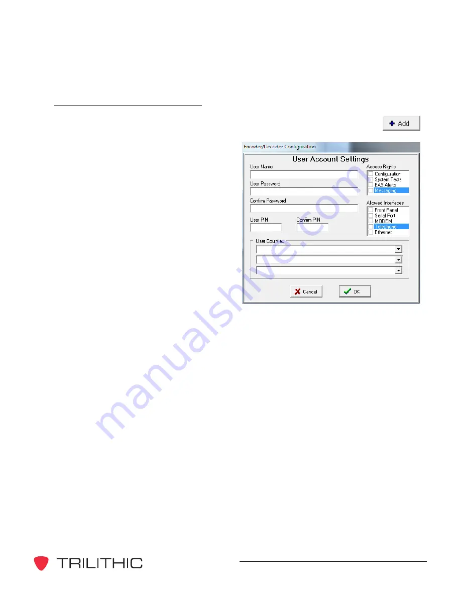
Adding a New User Account

1.  To create a new user account, click the 

Add 

button.  The 

 User Account 

Settings 

pop-up window will appear.

2.  Enter a unique 

User Name

.

3.  Enter a 

User Password

.

4.  Re-enter the password in the 

Confirm Password

 text box.

5.  Enter a 

User PIN 

(personal 

identification number) that the user 

will use for touch-tone telephone 

access.  The 

User PIN

 will also be 

used to access the EASyPLUS via 

the front panel.

6.  Re-enter the PIN in the 

Confirm PIN 

text box.

7.  Use the three pull-down 

User 

Counties

 lists to select the county or 

counties to include in EAS messages generated by the user.

8.  Select the check boxes which correspond to the features the user will have access 

to in the 

Access Rights

 group.

9.  Select the communication methods that the user can use in the 

Allowed Interfaces


group.

Click the 

OK 

button to add the new account as entered.

The new user will be displayed in the 

User Accounts 

group on the 

Users 

tab.

Summary of Contents for EASy-PLUS

Page 1: ...EASyPLUS EAS Encoder Decoder Version 8 09 Operation Manual ...

Page 2: ......

Page 3: ...arkets around the world As an ISO 9000 2001 certified company with over 40 years of collective expertise in engineering and custom assembly Trilithic is dedicated to providing quality products services and communications solutions that exceed customer expectations Trilithic is comprised of five major divisions Broadband Instruments and Systems Offers test analysis and quality management solutions ...

Page 4: ...EASyPLUS Encoder Decoder Operation Manual V8 09 2 THIS PAGE INTENTIONALLY LEFT BLANK ...

Page 5: ...1 Removing the EASyPLUS Configuration software 21 4 Initial Configuration 23 Starting the EASyPLUS Configuration software 23 Connecting the EASyPLUS to a Computer 23 Serial Connection 24 Modem Connection 25 Ethernet Connection 26 First Time EASyPLUS Network Configuration 27 Configure the EASyPLUS via the RS 232 Serial Port 27 5 EASyPLUS Configuration 29 Overview 29 The Main Tab 29 Adding and Manag...

Page 6: ...t 47 The Events Tab 48 Enabling and Configuring an Event 49 The Radios Tab 50 Configuring the Radios 51 The Audio Tab 52 Verifying Radio Reception 54 Recording an EAS Audio Message 55 The Users Tab 56 Adding a New User Account 57 Modifying an Existing User Account 58 Deleting a User Account 58 The IP Devices Tab 59 Configuring a DNCS Evertz Middleware Device 60 Configuring an SCTE 18 Device 64 Con...

Page 7: ...dio Function 91 Test the Character Generator Function 92 Test Outputs 93 Calibrate Hub Sites 94 Program IP Settings 95 Set User Defaults 95 Upgrading the EASyPLUS Firmware 96 Unlocking Licensed Features 100 6 Understanding EASyPLUS Logs 101 Overview 101 The Log Header 101 EAS Message Receipts 102 EAS Message Transmissions 103 EAS Message Receipt and Transmission 105 Non EAS Logs 107 TTL General Pu...

Page 8: ...EASyPLUS Encoder Decoder Operation Manual V8 09 6 THIS PAGE INTENTIONALLY LEFT BLANK ...

Page 9: ...S units maintaining configuration settings and log files for each encoder decoder Access to EAS logs stored within the EASyPLUS An interface for generating EAS messages The ability to upgrade firmware A convenient means of upgrading the EASyNIC card s firmware Chapter 1 1 General Information Helpful Website The following website contains information which may be of interest http www trilithic com ...

Page 10: ...ecoder A detailed description of the problem you are having including any error or information messages Before any Trilithic EAS encoder decoder can be returned for repair Trilithic will issue a return material authorization RMA number NO RETURNED EQUIPMENT WILL BE ACCEPTED WHICH DOES NOT HAVE AN RMA NUMBER PROMINENTLY DISPLAYED ON THE OUTSIDE SHIPPING CARTON AND ON THE SHIPPING LABEL A complete a...

Page 11: ...r 3 Software Installation details the procedure for installing the EASyPLUS Configuration software which will be used to configure and control the EASyPLUS Chapter 4 General Configuration Information provides information about interacting with the EASyPLUS connecting the EASyPLUS to the host computer and establishing communication between the EASyPLUS and the Configuration software Chapter 5 EASyP...

Page 12: ...bold Section names web and email addresses appear in italics A NOTE is information that will be of assistance to you related to the current step or procedure A CAUTION alerts you to any condition that could cause a mechanical failure or potential loss of data A WARNING alerts you to any condition that could cause personal injury Precautions Do not use the EASyPLUS Encoder Decoder in any manner not...

Page 13: ...if the encoder decoder s time is incorrect The firmware internal operating system of the EASyPLUS is upgradeable using a personal computer Check the EAS downloads section at www trilithic com frequently to determine if new firmware is available Check for new firmware prior to using the equipment for the first time as some EASyPLUS units have been warehoused and may not have the latest firmware Sta...

Page 14: ...EASyPLUS Encoder Decoder Operation Manual V8 09 12 THIS PAGE INTENTIONALLY LEFT BLANK ...

Page 15: ...resolution of at least 800 x 600 pixels 500 MHz processor with 512 MB of RAM and 1 5 GB of free hard drive space In addition the following are required in order to establish communications between the EASyPLUS Configuration software and the EASyPLUS Encoder Decoder 9 pin RS 232 interface or USB to RS 232 adapter if an Ethernet connection is not used 10 100 BaseT Ethernet network interface card wit...

Page 16: ...are to perform the following steps 1 Retrieve the current configuration from the EASyPLUS units and then save the configuration files to a safe location 2 On the I O Ports tab make sure that the Use Legacy Protocol option is turned off and then program the configuration to the EASyPLUS units 3 Download the logs from the EASyPLUS units and then save the log files to a safe location After upgrading ...

Page 17: ...un is enabled for the CD ROM drive the EASyPLUS Configuration setup program will start automatically If the setup program does not start click the Windows Start button then select Run and type drive setup exe then click the OK button substitute the appropriate drive letter in the command line in place of drive 4 Depending on which operating system you are using the Open File Security Warning dialo...

Page 18: ...eparing to Install window will appear momentarily to indicate the status of the software s installation 6 The Welcome to the InstallShield Wizard window for the EASyPLUS Configuration software will appear Click the Next button to continue with the installation ...

Page 19: ...ecoder Operation Manual V8 09 17 7 The License Agreement window will appear To continue with the installation select the radio button which corresponds with acceptance of the license agreement then click the Next button ...

Page 20: ...d Click the Change button to select a folder other than the default click the Next button to accept the default folder in which to install the EASyPLUS Configuration software If the software installation is an upgrade from a previous version of the EASyPLUS Configuration software select the same destination folder as the previous version in order to keep the previous configuration settings ...

Page 21: ...w confirms the settings for the installation of the EASyPLUS Configuration software If the information shown is correct click the Next button To change the installation settings click the Back button 10 The Installing Trilithic EASyPLUS window will appear momentarily to indicate the status of the software s installation ...

Page 22: ...em you are using you may need to log in as the system administrator 2 Download the latest version of the EASyPLUS Configuration software through Trilithic s EAS website www trilithicEAS com and save the setup file to the local hard disk or Windows desktop 3 Initialize the setup program by double clicking the Setup icon on the desktop on local hard disk 4 Follow the steps 4 through 11 in the Chapte...

Page 23: ... from the CD or Installing from the Internet section of this manual Removing the EASyPLUS Configuration software To remove the EASyPLUS Configuration software from the host computer the Windows Add or Remove Programs utility can be used Open the Add or Remove Programs utility by clicking the Windows Start button then the Control Panel program From the Control Panel click the Programs and Features ...

Page 24: ...EASyPLUS Encoder Decoder Operation Manual V8 09 22 THIS PAGE INTENTIONALLY LEFT BLANK ...

Page 25: ...ct to a remote system Connecting the EASyPLUS to a Computer Before connecting the EASyPLUS Encoder Decoder to the computer on which the EASyPLUS Configuration software is installed determine which type of connection will be used between the EASyPLUS and the host computer serial Ethernet or modem Refer to the following procedures for instructions in establishing a connection between the EASyPLUS an...

Page 26: ...utton 5 On the pop up Select Type of Communications Port window select the radio button corresponding to Serial Modem then click the Accept button 6 In the pop up Device Selection window select the PC COM Port from the pull down list then click the OK button If the desired port is not shown in the Device Selection pull down list Windows does not properly recognize the device and a Windows driver m...

Page 27: ... port is not shown in the Device Selection pull down list Windows does not properly recognize the device and a Windows driver may need to be installed 7 Enter the telephone number for the desired system in the Telephone Number text box including any digits needed to access an outside line 1 for long distance 9 for an outside line etc A comma can be used to add a pause to the dialing and dashes or ...

Page 28: ...tructed by your IT administrator enter the default TCP port number of 59911 3 Click the Disconnect button 4 Click the Select COM Port button 5 On the pop up Select Type of Communications Port window select the radio button corresponding to Ethernet then click the Accept button Connections made via the EASyPLUS s Ethernet port do not require that the Connect button be clicked the program automatica...

Page 29: ...LUS Configuration software to the EASyPLUS via a serial connection Refer to Chapter 5 EASyPLUS Configuration The Main Tab 2 Start the EASyPLUS Configuration software 3 On the Interfaces tab in the Network Settings group enter the Static IP Address Subnet Mask Default Gateway and Command TCP Port for the EASyPLUS as provided by your IT administrator 4 Click the Program IP Settings button on the Uti...

Page 30: ...EASyPLUS Encoder Decoder Operation Manual V8 09 28 THIS PAGE INTENTIONALLY LEFT BLANK ...

Page 31: ...de to the configuration will have no effect on the EASyPLUS until the settings are uploaded by clicking the Program Configuration button on the Main tab The Main Tab The Main tab is used to set up communications between the EASyPLUS Configuration software and the EASyPLUS Encoder Decoder and to send or receive configuration data to and from the device The parameters on the Main tab must be configu...

Page 32: ...ab From the pop up window select the desired configuration by clicking on it once then click the Accept button To add a new configuration to the list click the Add button on the Main tab Enter a unique name for the new configuration in the System Name field of the Add a New EASyPLUS System pop up window then click the Accept button To delete a configuration from the list click the Delete button on...

Page 33: ...stem Name field of the Modify an EASyPLUS System pop up window then click the Accept button Enter the IP address of the selected EASyPLUS in the IP Address text box if connecting via Ethernet Enter the TCP Port that will be used to communicate with the EASyPLUS the default value is 59911 If connecting via Modem enter the modem telephone number of the selected EASyPLUS in the Telephone Number text ...

Page 34: ...up window will appear next From the pull down list select the desired modem or COM port then click the OK button A valid telephone number must be entered in the Telephone Number text box if connecting via Modem Ethernet In order to connect via Ethernet a valid IP address must be entered in the IP Address text box and the TCP port must be correct Connect to the selected EASyPLUS by clicking the Con...

Page 35: ...figuration The configuration parameters for the selected EASyPLUS can be downloaded to the EASyPLUS Configuration software To download the EASyPLUS s configuration parameters to the Configuration software click the Retrieve Configuration button Setting the EASyPLUS Time The EASyPLUS s internal time can be set by synchronizing it with the computer on which the EASyPLUS Configuration software is ins...

Page 36: ...port To export a configuration file first select the system as described in Chapter 5 EASyPLUS Configuration The Main Tab 1 On the Main tab click the Export Configuration button 2 The Export EASyPLUS Configuration window will appear navigate to the folder that the configuration file will be saved to Type a name for the file then click the Save button to export the configuration file ...

Page 37: ...select the system as described in Chapter 5 EASyPLUS Configuration The Main Tab 1 On the Main tab click the Import Configuration button 2 A File Open window will appear navigate to the configuration file Select the file then click the Open button to load the configuration file Importing a configuration will overwrite all information for the selected system Make sure that the correct system is sele...

Page 38: ...have no effect on the EASyPLUS until the settings are uploaded by clicking the Program Configuration button on the Main tab The General Tab The General tab contains settings for the basic interfaces of the EASyPLUS Encoder Decoder as well as miscellaneous controls that affect its behavior ...

Page 39: ...to select the language used for alert text 4 Analog to Digital Playback Delay Enter the time in seconds to delay the analog playback after network alerts are delivered 5 Enable Custom Messages With this check box selected the EASy Custom Messaging program can access and control the EASyPLUS 6 Enable Zone Routing using the TTL32 expansion card Checking this box allows for county routing equipment A...

Page 40: ... to tune to this channel for further details Use Short RWT Text A short message will be used for Required Weekly Tests For example A Required Weekly Test has been issued by an EAS Participant Front Panel RWT Includes All Counties Include all configured counties when encoding an RWT from the front panel menu If disabled only the county of license will be included Enable the National Location Code E...

Page 41: ...ly encode an RWT every week using the county of license as the FIPS code Enabled Using Selected Counties Select this option from the pull down list to encode RWT messages with all of the configured counties Using the Between the Days and Between the Hours pull down lists specify a span of days and hours in which the RWT will be generated Precise scheduling is not permitted in order to assure compl...

Page 42: ... to be seen at the video output Full CG Page During EAS This option loops the video input through to the video output except when an EAS message is in progress at which time the EAS page is seen at the output 3 Use the Color pull down list to select a color scheme for the crawl text 4 Use the Crawl Position control box to select the area in which an EAS crawl will be shown 1 is at the top of the s...

Page 43: ...der that contains the Ethernet modem EASyNIC option Changes made on the Interfaces tab will have no effect on the EASyPLUS until the settings are uploaded by clicking the Program Configuration button on the Main tab Changes made on the Interfaces tab require the EASyPLUS to be rebooted to take effect The EASyPLUS may be rebooted using the Reset Hardware button on the Utilities tab ...

Page 44: ...ox The default value is 59912 7 Enter the IP TTL time to live value for TCP and unicast UDP 4 Enter the port desired to receive audio from EASyCAP series software or devices in the Audio TCP Port box The default value is 59919 7 Enter the Multicast TTL value maximum hops for multicast UDP packets 8 If the Disable FTP Server option is selected the internal FTP server will not be available once the ...

Page 45: ...essages manually originated by an operator or messages automatically generated by the EASyPLUS random RWT messages 3 Select the Deliver Non EAS messages check box to deliver custom not EAS messages 4 Enter the TCP port used to deliver messages in the EAS Server TCP Port box The default value is 59901 COM 2 Device Settings The COM 2 Device Settings group is used to configure the COM 2 Serial Port t...

Page 46: ...ntrol box to the time in minutes until the modem disconnects from an idle no data transmitted connection 5 Set the Telephone Timeout if No Activity Occurs for control box to the time in seconds until the telephone disconnects if no buttons are pressed on the telephone NTP Settings EAS messages use a time stamp to help determine if messages should be retransmitted An accurate EAS clock is crucial f...

Page 47: ... by a monitored radio station The counties that the system serves must be included in the county list Nearby counties may be included as well The term county is used loosely and may be a city or other area specified in the FIPS standard used in EAS Changes made on the Counties tab will have no effect on the EASyPLUS until the settings are uploaded by clicking the Program Configuration button on th...

Page 48: ...Click the Add button 3 From the pop up window select the state that the counties reside in from the Select a State pull down list 4 In the Select County City area highlight the county to be added and then click the OK button The county will appear in the Selected Counties list Multiple counties can be selected by holding the Control CTRL key while clicking on each county name ...

Page 49: ...vent the EASyPLUS from transmitting EAS messages received for that specific County Subdivision 4 Use the check boxes to select which routing zones will be processed The routing zones are used to control the TTL 32 Expansion Board if installed Each zone corresponds to a TTL output on the TTL 32 Expansion Board This is primarily used with a SM 16 to perform trunk switching These routing zones only a...

Page 50: ...the method of sending each event is configured An event is identified with a three letter code in the EAS protocol that provides a generic description of a federal civil or weather related hazard condition or test By configuring each of the events the EASyPLUS administrator can choose which hazards are important enough to interrupt the broadcast ...

Page 51: ...transmitted 3 The Event Priority control box configures the priority level for the selected event This is used by devices receiving SCTE 18 digital messages in order to determine if audio or force tuning is required 4 The Alert Type pull down list is used to select the color scheme used on the Trilithic Visionary HD SD Overlay devices 5 The Display Mode pull down list determines how the event will...

Page 52: ...ab allows the configuration of up to four internal radios their respective bands and the frequencies each radio monitors Changes made on the Radios tab will have no effect on the EASyPLUS until the settings are uploaded by clicking the Program Configuration button on the Main tab ...

Page 53: ...xpansion 2 Channels 3 4 group select the radio button corresponding to the device installed in each of the audio expansion ports 2 In each of the available Radio Receiver groups select the radio band corresponding to each of the radio receivers installed in the EASyPLUS AM FM or NOAA 3 In each of the available Radio Receiver groups select the frequency which each radio receiver will tune to Refer ...

Page 54: ...mes selection of speaker and master output audio sources for checking radio reception and recording or playing back internally stored audio messages For convenience while adjusting audio volume and checking radios the Upload Audio Configuration button can be used in place of the Program Configuration button on the Main tab ...

Page 55: ...s received Master Output Volume This control sets the volume of all EAS audio outputs from the EASyPLUS This includes the volume of the audio switch output during EAS operations Source This pull down list is used to temporarily route an input line to audio outputs 1 through 4 on the back of the EASyPLUS The normal position for this control is DSP Telephone Volume This control is used to set the de...

Page 56: ...EASyPLUS to record a message from the front panel microphone While the message is being recorded the Record button will change to a Stop button Click the Stop button to end the audio tone playback Playback Click this button to play the audio message that has been recorded While the audio message is playing the Playback button will change to a Stop button Click the Stop button to end the audio mess...

Page 57: ...H5 or CH6 as necessary if using an external line level source 3 Click the Record button and speak into the microphone 4 Click the Stop button to end the recording session the Record button changes to the Stop button while recording is in progress 5 Under the Speaker Volume slider select DSP from the Source pull down list then click the Program Audio Configuration button 6 Click the Playback button...

Page 58: ... Encoder Decoder is only available to users for which a valid account has been created through the EASyPLUS Configuration software Changes made on the Users tab will have no effect on the EASyPLUS until the settings are uploaded by clicking the Program Configuration button on the Main tab ...

Page 59: ... access The User PIN will also be used to access the EASyPLUS via the front panel 6 Re enter the PIN in the Confirm PIN text box 7 Use the three pull down User Counties lists to select the county or counties to include in EAS messages generated by the user 8 Select the check boxes which correspond to the features the user will have access to in the Access Rights group 9 Select the communication me...

Page 60: ...y Access Rights or Allowed Interfaces 4 Click the OK button to add the new account as entered Deleting a User Account 1 On the Users tab click the user account to be modified 2 Click the Delete User button The EASyPLUS Configuration software will not allow multiple user accounts to be created with the same password or PIN Each user account must be assigned a unique password The user password must ...

Page 61: ... between the EASyPLUS Encoder Decoder and IP controlled devices which are needed to air the message The configuration process for each type of device includes selecting the communications protocol entering the information needed to establish a connection and selecting the locations and users that the remote IP device serves ...

Page 62: ...e The DNCS Evertz Middleware tab is used to configure communications with a SA DNCS middleware servers and character generators The configuration process includes selecting a communication protocol entering the IP and port information and selecting the locations and users that the device serves ...

Page 63: ...Port number used the default setting is 4098 6 Enter the FTP Username 7 Enter the FTP Password 8 If the iTV Manager protocol is used enter a number to identify the EASyPLUS in the Token control box The token number helps the EAC distinguish between multiple encoder decoders 9 If the Use the EAS Duration check box is not selected a value of zero will be sent 10 Select the Include Text File with an ...

Page 64: ...erves as well as the users the device serves This option will allow each device to serve a different geographical location and to prevent unnecessary interruption if the message is not intended for the location serviced 13 Select the Enable All Locations check box to disable location routing and send all messages to the device 14 Click the OK button to accept the configuration 15 Click the OK butt...

Page 65: ...he configuration changes Deleting a DNCS Evertz Middleware Device To delete a device perform the following procedure 1 Select the device then click the Delete button 2 A status window will briefly appear after the window closes the selected device will no longer be displayed Testing a DNCS Evertz Middleware Device Click the Test button to send a simulated EAS alert to the selected device The Test ...

Page 66: ...09 64 Configuring an SCTE 18 Device SCTE 18 messages contain all the information in the EAS protocol text as well as text translation and timing information that downstream devices may use to display a text crawl and time the replacement of audio ...

Page 67: ... the Repeat Rate control box set the value to 0 for no repeats 8 Use the Details Source control box to provide the out of band source information for the EAS details channel 9 Use the Audio Source control box to provide the information contained in the audio_OOB_source_ID field of the SCTE 18 message Select the source ID from 0 to 65535 This value is typically set to 0 10 Use the Major Channel con...

Page 68: ...veral SCTE 18 devices so that their configurations can be managed as a group Refer to the Adding an SCTE 18 Device to a Group section 19 Set the Repeat new messages value as necessary to send multiple copies of a new EAS message in order to establish an MPEG stream The continuity_ indicator will be incremented for each packet sent 20 Click the Locations button to select which counties will activat...

Page 69: ...7 To modify an existing exception highlight it change the settings then click the MODIFY button 28 To delete a configured exception select the exception from the Exception List then click the Delete button 29 Click the OK button to save changes to the SCTE 18 Exceptions 30 Up to 4 SCTE 18 descriptors can be added to an SCTE 18 message If the Vecima descriptor is used only one descriptor is allowed...

Page 70: ...is entered as hexadecimal values All of the descriptor data including the descriptor_tag and descriptor_length must be included 35 To edit a descriptor select a descriptor to edit from the SCTE 18 Descriptors pull down list and then click the Edit button Edit the settings and then click the OK button to save the configuration changes 36 To delete a descriptor select a descriptor to delete from the...

Page 71: ...e device parameters individually To add an SCTE 18 device to a group perform the following procedure 1 Select an existing device that will be the basis for the device you are adding then click the Add Group button 2 The pop up Add an SCTE 18 Recipient window will appear 3 Follow the same procedure used to add an SCTE 18 device Editing an SCTE 18 Group Editing device parameters as part of a group a...

Page 72: ... longer be displayed Testing an SCTE 18 Device Click the Test button to send a simulated EAS alert to the selected device The Test button is intended as a setup and troubleshooting tool It does not replace a legitimate EAS message and does not satisfy any legal requirements for EAS testing Configuring an IP Switch Device IP switches allow contact closures to be used at distant locations via networ...

Page 73: ...te with the remote IP switch the default setting is 9100 5 From the Locations Users Serviced list select the check box corresponding to the county or counties that the IP switch will serve This option will allow each IP switch device to serve a different geographical location and to prevent unnecessary interruption if the message is not intended for the location serviced by the IP switch device 6 ...

Page 74: ... perform the following procedure 1 Select the device to be deleted from the IP Switch Devices list then click the Delete button 2 A status window will briefly appear after the window closes the selected device will no longer be displayed Testing an IP Switch Device To perform a test of an IP switch device first select the device to be tested from the IP Switch Devices window This test is used to v...

Page 75: ...ameters 1 Select the Show EAS Event Static Text check box if the EAS event name should be shown Use the Position control box to set the vertical location for the EAS text The top edge of the text is referenced by the location coordinate 1 is closest to the top of the screen 479 is closest to the bottom of the screen Use the Size control box to set the size in points of the EAS text 1 is the smalle...

Page 76: ... software Refer to the Visionary Configuration software manual for instruction in EAS font configuration 3 In the Crawl and Text Colors group set the color display parameters for the on screen display of EAS crawl and static text This group allows custom color settings to be applied to each type of EAS alert watches warnings tests etc Use the top left pull down list to select the text to be config...

Page 77: ...on of the Visionary 7 Select the Show EAS Alert Image check box to display an on screen EAS image or icon to accompany the EAS event 8 Use the EAS Alert Image X Position control box to set the horizontal location for the EAS image or icon 1 is furthest left 852 is furthest right 9 Use the EAS Alert Image Y Position control box to set the vertical location for the EAS image or icon 1 is closest to ...

Page 78: ...Input GPI 4 check box to force the Visionary to wait for an open condition on the Visionary s general purpose input 4 contact closure prior to sending the message 16 Click the Locations button to display a list of counties 17 In the pop up Select All Serviced Locations Users window select the county or counties that the Visionary device will serve as well as the users who can activate the Visionar...

Page 79: ... Adding a Visionary Device Refer to the Adding a Visionary Device section for detailed instructions in editing a Visionary Overlay device 3 Click the OK button to complete the editing process Deleting a Visionary Device To delete a Visionary configuration select the device from the Visionary Overlay Devices list by clicking on it once then click the Delete button Testing a Visionary Device Click t...

Page 80: ...rotocol SNMP options including enabling and disabling SNMP capabilities and configuring IP addresses for trap recipients SNMP servers Changes made on the Management tab will have no effect on the EASyPLUS until the settings are uploaded by clicking the Program Configuration button on the Main tab Changes may also require a reboot to take effect ...

Page 81: ... be confirmed for transmit Allow Alerts to be Encoded Select this option to allow EAS messages to be encoded transmitted using SNMP This should only be enabled for laboratory use or for generating the required weekly test Allow System Control Tests Select this check box to allow the EASyPLUS outputs to be controlled over SNMP Allow Configuration via SNMP Select this check box to allow a limited nu...

Page 82: ... to enable periodic traps indicating the EASyPLUS is online and functioning The heartbeat trap frequency averages two traps per minute 5 Select the Enable Fault Status Trap Messages check box to enable fault and status trap messages Refer to the current MIB for details 6 Select the Enable EAS Activation Trap Messages check box to enable EAS activation traps EAS activation trap messages are used to...

Page 83: ...rvers list then click the Delete button Editing an SNMP Server To edit an SNMP server in the list 1 Select the server in the SNMP Management Servers list then click the Edit button 2 The pop up SNMP Server Settings window will appear The process to edit an SNMP server is the same as adding a new server outlined in Chapter 5 EASyPLUS Configuration The Management Tab Adding an SNMP Server 3 Click th...

Page 84: ...est messages are received from each monitored radio station The EAS log is proof to the FCC that receipts and activations have occurred EASyPLUS logs may be sent to a printer connected to the parallel port as they occur or the EAS logs may be retrieved from the internal memory of the EASyPLUS via the Configuration Program Retrieved logs may be saved as a text file allowing logs to be easily stored...

Page 85: ... file It is suggested that the file name include the station call letters and current date for easy identification WTRI EAS Log 08 12 09 Click the Save button 5 Verify that the newly saved log file has been saved correctly 6 Click the Delete button to remove EAS logs from the EASyPLUS s memory The Delete button will clear the memory in the EASyPLUS This step cannot be undone 7 A pop up window will...

Page 86: ... not pertaining to alerts Additional Functions The following option only applies to the Configuration software display Word Wrap Select this check box to wrap text lines which do not fit within the boundaries of the EASyPLUS Log window The following options are EASyPLUS configuration options Printer Port Use the Printer Port pull down list to disable the printer port of the EASyPLUS or to enable i...

Page 87: ...non configuration tools that are needed to control test and determine the status of the EASyPLUS Encoder Decoder or the EASyPLUS Configuration software Connect the EASyPLUS to the computer on which the EASyPLUS Configuration software is installed as outlined in Chapter 5 EASyPLUS Configuration The Main Tab ...

Page 88: ...r button Originate an EAS Alert The EASyPLUS Configuration software allows an operator to originate an EAS event All originated messages other than a Required Weekly Test will be accompanied by an audio message The audio that accompanies the originated EAS alert will be the last audio message that was recorded by the EASyPLUS This may be warning audio from a prior EAS alert Before originating an E...

Page 89: ...onfiguration that alters the network settings including any settings that require the EASyPLUS to monitor additional Ethernet ports Verify the EASyPLUS s System Time Click Check Time button to retrieve the current time of the EASyPLUS s clock 3 Select the event to be distributed from the Select Event pull down list in the updated Utilities tab 4 In the Event Duration group select the time in Hours...

Page 90: ...he About button on the Utilities tab to view general information about the EASyPLUS Configuration software the connected EASyPLUS Encoder Decoder and the software license agreement The Unique Identifier shown on the about screen may be required when ordering product keys 3 Click the OK button to return to the normal Utilities tab ...

Page 91: ...form the following procedure 1 Click the Calibrate Audio button The Utilities window will refresh to display the Audio FSK and Attention Tone Settings window Use the Master Output Volume control on the Audio tab to adjust all EAS tones and the voice playback simultaneously 2 Use the ATT 853 Hz Amplitude control to set the relative volume of the 853 Hz tone part of the EAS dual tone attention tone ...

Page 92: ...ration parameters to the EASyPLUS The Audio Tone Calibration group is used to generate the tones used in EAS It allows the tones to be played individually or combined to create specific EAS tones 7 Use the Select Audio Tone pull down list to select which of the tones to play 8 Click the Play Tone button to start the tone When the audio tone begins playing the Play Tone button will change to a Stop...

Page 93: ...ll audio tests have been completed click the Close button to return to the normal Utilities tab Test the Audio Function The EASyPLUS audio tests allow an operator to activate specific control lines while sending EAS tones or recorded voice messages In order to perform these tests the operator should know which TTL and contact closures if any are connected to the audio substitution equipment 1 If u...

Page 94: ... the Character Generator Test Utility window 2 In the Main TTLs Contact Closures group select the control lines needed to route video If an attention tone is to be used select the audio routing control lines as well 3 In the CG Display Mode group select the radio button corresponding to the desired Page Caption or Crawl mode 4 Select the Play Attenuation Tone check box to play an audio tone with t...

Page 95: ...on to return to the normal Utilities tab Test Outputs The EASyPLUS Configuration software allows an operator to test the TTL outputs To test the TTL outputs click the Test Outputs button Expansion TTL tests require the TTL Expansion Board Select the TTL or Contact Closure to test and then click the Start Test button The selected output will be activated Click the Stop Test button when finished the...

Page 96: ...trollers window The address of the Virtual Controller must be set to 0 all DIP switches down for calibration 2 Click the Start Calibration button to start the calibration tone If the AFSK audio volume from the EASyPLUS needs to be changed go to the Audio tab and adjust the Hub Site AFSK Volume 3 Click the Stop Calibration button to end the calibration tone the button will change to Stop Calibratio...

Page 97: ...rs over the interface specified on the Main tab The EASyPLUS must be rebooted after changing network settings Set User Defaults Click this button to revert the encoder decoder user accounts to their default values Once the default settings have been programmed the administrator password Administrator can be used to access the EASyPLUS This command only works over the RS 232 serial interface ...

Page 98: ... EASyPLUS does not have the EASyNIC card installed an RS 232 serial port must be used to upgrade the firmware Connect a serial null modem cable provided with the EASyPLUS between the COM 1 port of the EASyPLUS and an available RS 232 serial port on the host computer If the EASyPLUS contains an EASyNIC card an Ethernet cable must be connected between the EASyPLUS and the host computer The EASyPLUS ...

Page 99: ... is required to upgrade the EASyNIC firmware If a serial port is used for the firmware upgrade press the Select Com Port button to select the correct computer serial port A window will pop up to allow the serial port to be selected from the list of available devices Connect the serial cable between this port on the computer and the COM 1 port on the EASyPLUS If Ethernet is used for the firmware up...

Page 100: ...yPLUS The LCD will display the EASyPLUS flash loader version retry the firmware upgrade 6 Click the Continue button to update the files listed or click the Program All Files button to update all files including those that are already up to date 5 Click the Continue button again to proceed with the firmware upgrade The screen will refresh to display the firmware selections that will be upgraded The...

Page 101: ...8 09 99 7 The screen will refresh to display a progress screen The upgrade process may take as much as 10 minutes 8 When the firmware upgrade is complete a confirmation message will be displayed Click the OK button to return to the Utilities tab ...

Page 102: ...taining the available features that can be unlocked 2 Contact Trilithic via email at EASsales trilithic com to obtain a license key for the desired feature or features 3 Enter the key code in the Enter Product Key field then click the Continue button With the EASyPLUS Configuration software connected to the encoder decoder click the About button on the Utilities tab then highlight and copy the tex...

Page 103: ... the case when the logs are from peripheral devices or when the encoder decoder has grouped together related information The Log Header The first lines of the EASyPLUS log if downloaded from the EASyPLUS Configuration software contain the date and time that the log was downloaded the number of records downloaded and the versions of the encoder decoder software components The following is an exampl...

Page 104: ...coded Originator EAS Participant The type of organization that first sent the message Event Required Monthly Test The EAS event 1 of 53 predefined events Origination Time 10 02 09 18 15 00 EDT The encoder decoder time when the message was first sent Expiration Time 10 02 09 18 30 00 EDT The effective until time of the message origination duration 10 02 09 18 17 20 EDT Receive Log Originator EAS Pa...

Page 105: ... account responsible for the message and a message ID generated at log time This information contained within the EAS message may help the reader to associate related logs with each other For details on EAS messages refer to title 47 part 11 of the Code of Federal Regulations 47 CFR part 11 The following is an example of an EAS transmission log 10 02 09 18 19 00 EDT Transmit Log Originator EAS Par...

Page 106: ... 2752218 ENG TEST The actual EAS code string transmitted Alert Text An EAS Participant has issued a Civil Emergency Message for the following counties Franklin IN Marion IN Effective Until 10 02 09 18 33 00 EDT ENG TEST An English translation of the code string transmitted Operator ID 1F4 Initiated an Alert Message at 10 02 09 18 18 19 EDT The ID of the login used to generate the message and the t...

Page 107: ...09 18 15 35 EDT Received from Channel 5 Call Letters WIRA FM Received Attention Tone at 10 02 09 18 15 40 EDT Received Voice Message at 10 02 09 18 15 48 EDT Received EOM at 10 02 09 18 16 11 EDT Retransmitted the EAS Message at 10 02 09 18 16 30 EDT Transmitted 8 second Attention Tone at 10 02 09 18 16 36 EDT Transmitted 21 second Voice Message at 10 02 09 18 16 45 EDT Transmitted EOM at 10 02 09...

Page 108: ...tion that the message was received from Received Attention Tone at 10 02 09 18 15 40 EDT The encoder decoder time at which the attention tone was detected Received Voice Message at 10 02 09 18 15 48 EDT The encoder decoder time at which the voice message was detected Received EOM at 10 02 09 18 16 11 EDT The encoder decoder time at which the end of message was detected Retransmitted the EAS Messag...

Page 109: ...lerts set to Full System and during Tune To messages TTL 8 Output Substitution Audio Output This output is activated anytime audio is replaced on all of the channels This occurs during the audio portion of alerts set to Full System and during Tune To messages TTL 9 Delayed Substitution Output This output is activated along with the other substitution outputs except that it goes active before the o...

Page 110: ...EASyPLUS Encoder Decoder Operation Manual V8 09 108 THIS PAGE INTENTIONALLY LEFT BLANK ...

Page 111: ... been handled and used as set forth in the documentation accompanying the product and or its packaging This limited warranty shall not apply to any damage due to accident misuse abuse neglect fire or other casualty Further this limited warranty shall not apply to any product which has been altered or where the damage was caused by a part not supplied by Trilithic Trilithic retains the final decisi...

Page 112: ...EASyPLUS Encoder Decoder Operation Manual V8 09 110 THIS PAGE INTENTIONALLY LEFT BLANK ...

Page 113: ......

Page 114: ...9710 Park Davis Drive Indianapolis IN 46235 317 895 3600 www trilithic com P N 0010210003 9 14 Made in U S A ...

Reviews: