Switch Clustering
3-195
3
Once a switch has been configured to be a cluster Commander, it automatically
discovers other cluster-enabled switches in the network. These “Candidate”
switches only become cluster Members when manually selected by the
administrator through the management station.
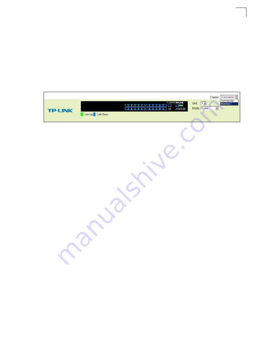
After the Commander and Members have been configured, any switch in the cluster
can be managed from the web interface by choosing the Member ID from the
Cluster drop-down menu. From the Commander CLI prompt, use the “rcommand”
command (see 4-240) to connect to the Member switch.
Figure 3-122 Cluster Member Choice
Cluster Configuration
To create a switch cluster, first be sure that clustering is enabled on the switch (the
default is enabled), then set the switch as a Cluster Commander. Set a Cluster IP
Pool that does not conflict with the network IP subnet. Cluster IP addresses are
assigned to switches when they become Members and are used for communication
between Member switches and the Commander.
Command Attributes
•
Cluster Status
– Enables or disables clustering on the switch.
•
Cluster Commander
– Enables or disables the switch as a cluster Commander.
•
Role
– Indicates the current role of the switch in the cluster; either Commander,
Member, or Candidate.
•
Cluster IP Pool
– An “internal” IP address pool that is used to assign IP addresses
to Member switches in the cluster. Internal cluster IP addresses are in the form
10.
x.x.member-ID
. Only the base IP address of the pool needs to be set since
Member IDs can only be between 1 and 16. Note that y
ou cannot change the cluster
IP pool when the switch is currently in Commander mode. Commander mode must first
be disabled.
•
Number of Members
– The current number of Member switches in the cluster.
•
Number of Candidates
– The current number of Candidate switches discovered
in the network that are available to become Members.
Summary of Contents for TL-SG5426 -
Page 1: ...TL SG5426 26 Port Gigabit Managed Switch Rev 1 0 0 1910010105...
Page 17: ...Contents xiv...
Page 21: ...Tables xviii...
Page 25: ...Figures xxii...
Page 42: ...Initial Configuration 2 10 2...
Page 107: ...Configuring the Switch 3 64 3 Figure 3 41 802 1X Port Configuration...
Page 486: ...Software Specifications A 4 A...


