background image

Greensmaster 3320/3420

Hydraulic System

Page 5 -- 1

Chapter 5

Hydraulic System

Table of Contents

SPECIFICATIONS

3

. . . . . . . . . . . . . . . . . . . . . . . . . . . .

GENERAL INFORMATION

4

. . . . . . . . . . . . . . . . . . . . .

Operator’s Manuals

4

. . . . . . . . . . . . . . . . . . . . . . . . .

Check Hydraulic Fluid Level

4

. . . . . . . . . . . . . . . . . .

Pushing Traction Unit

4

. . . . . . . . . . . . . . . . . . . . . . . .

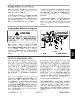
Relieving Hydraulic System Pressure

5

. . . . . . . . . .

Opening Electrical Circuit to Cutting Units

5

. . . . . .

Traction Circuit Component Failure

5

. . . . . . . . . . . .

Hydraulic Hoses

6

. . . . . . . . . . . . . . . . . . . . . . . . . . . .

Hydraulic Hose and Tube Installation (O--Ring

Face Seal Fitting)

7

. . . . . . . . . . . . . . . . . . . . . . . . .

Hydraulic Fitting Installation (SAE Straight Thread

O--Ring Fitting into Component Port)

8

. . . . . . . . .

HYDRAULIC SCHEMATIC

10

. . . . . . . . . . . . . . . . . . . .

HYDRAULIC FLOW DIAGRAMS

12

. . . . . . . . . . . . . . .

Traction Circuit

12

. . . . . . . . . . . . . . . . . . . . . . . . . . . .

Lower Cutting Units

14

. . . . . . . . . . . . . . . . . . . . . . . .

Raise Cutting Units

16

. . . . . . . . . . . . . . . . . . . . . . . . .

Right and Left Turn

18

. . . . . . . . . . . . . . . . . . . . . . . . .

SPECIAL TOOLS

20

. . . . . . . . . . . . . . . . . . . . . . . . . . . .

TROUBLESHOOTING

24

. . . . . . . . . . . . . . . . . . . . . . . .

General Hydraulic System Problems

24

. . . . . . . . . .

Traction Circuit Problems

25

. . . . . . . . . . . . . . . . . . .

Lift/Lower Circuit Problems

26

. . . . . . . . . . . . . . . . . .

Steering Circuit Problems

27

. . . . . . . . . . . . . . . . . . .

TESTING

28

. . . . . . . . . . . . . . . . . . . . . . . . . . . . . . . . . . .

Charge Relief Valve Pressure Test

30

. . . . . . . . . . .

Piston (Traction) Pump Flow Test

32

. . . . . . . . . . . .

Wheel Motor Efficiency Test

34

. . . . . . . . . . . . . . . . .

Steering/Lift Relief Valve Pressure Test

36

. . . . . . .

Lower Cutting Units Relief Valve (RV)

Pressure Test

38

. . . . . . . . . . . . . . . . . . . . . . . . . . . .

Steering/Lift Circuit Gear Pump Flow Test

40

. . . . .

Power Steering Valve Test

42

. . . . . . . . . . . . . . . . . . .

ADJUSTMENTS

44

. . . . . . . . . . . . . . . . . . . . . . . . . . . . .

Adjust Manifold Relief Valves

44

. . . . . . . . . . . . . . . .

Adjust Traction Control Assembly

45

. . . . . . . . . . . .

SERVICE AND REPAIRS

46

. . . . . . . . . . . . . . . . . . . . .

General Precautions for Removing and

Installing Hydraulic System Components

46

. . . .

Flush Hydraulic System

47

. . . . . . . . . . . . . . . . . . . . .

Filtering Closed--Loop Traction Circuit

48

. . . . . . . .

Hydraulic System Start--up

49

. . . . . . . . . . . . . . . . . .

Gear Pump

50

. . . . . . . . . . . . . . . . . . . . . . . . . . . . . . . .

Gear Pump Service

52

. . . . . . . . . . . . . . . . . . . . . . . .

Piston (Traction) Pump Neutral Assembly

54

. . . . .

Piston (Traction) Pump

56

. . . . . . . . . . . . . . . . . . . . .

Piston (Traction) Pump Service

60

. . . . . . . . . . . . . .

Piston Pump Crush Ring Replacement

62

. . . . . . . .

Front Wheel Motors

64

. . . . . . . . . . . . . . . . . . . . . . . .

Rear Wheel Motor (Optional 3WD)

66

. . . . . . . . . . .

Wheel Motor Service

68

. . . . . . . . . . . . . . . . . . . . . . .

Lift Cylinders

70

. . . . . . . . . . . . . . . . . . . . . . . . . . . . . .

Lift Cylinder Service

72

. . . . . . . . . . . . . . . . . . . . . . . .

Lift Control Manifold

74

. . . . . . . . . . . . . . . . . . . . . . . .

Lift Control Manifold Service

76

. . . . . . . . . . . . . . . . .

Control Manifold Cartridge Valve Service

78

. . . . . .

Power Steering Valve

80

. . . . . . . . . . . . . . . . . . . . . . .

Power Steering Valve Service

82

. . . . . . . . . . . . . . . .

Steering Cylinder

84

. . . . . . . . . . . . . . . . . . . . . . . . . .

Steering Cylinder Service

86

. . . . . . . . . . . . . . . . . . .

Hydraulic Reservoir

88

. . . . . . . . . . . . . . . . . . . . . . . .

Leak Detector Tank (Machines Equipped with

Optional Turf Guardian

t

Leak Detector

System)

90

. . . . . . . . . . . . . . . . . . . . . . . . . . . . . . . . .

Leak Detector Solenoid Valve Assembly (Machines

Equipped with Optional Turf Guardian

t

Leak

Detector System)

94

. . . . . . . . . . . . . . . . . . . . . . . . .

EATON, MEDIUM DUTY PISTON PUMP, REPAIR

INFORMATION,

MODEL

70160

VARIABLE

DISPLACEMENT PISTON PUMP

PARKER TORQMOTOR

TM

SERVICE PROCEDURE

(TC, TB, TE, TJ, TF, TG, TH AND TL SERIES)

SAUER/DANFOSS STEERING UNIT TYPE OSPM

SERVICE MANUAL

Hy

draulic

Sy

st

em

Summary of Contents for Greensmaster 3420 TriFlex

Page 1: ...manual Additional copies of the Operator s Manuals and Parts Catalog are available on the internet at www Toro com The Toro Company reserves the right to change product specifications or this publication without notice This safety symbol means DANGER WARNING or CAUTION PERSONAL SAFETY INSTRUC TION When you see this symbol carefully read the instructions that follow Failure to obey the instructions...

Page 2: ...Greensmaster 3320 3420 This page is intentionally blank ...

Page 3: ...tments 5 44 Service and Repairs 5 46 EATON MEDIUM DUTY PISTON PUMP REPAIR INFORMATION MODEL 70160 VARIABLE DISPLACEMENT PISTON PUMP PARKER TORQMOTORTM SERVICE PROCEDURE TC TB TE TJ TF TG TH AND TL SERIES SAUER DANFOSS STEERING UNIT TYPE OSPM SERVICE MANUAL Chapter 6 Electrical System General Information 6 2 Electrical System Operation 6 4 Turf Guardian Leak Detector System Operation 6 6 Special To...

Page 4: ...Greensmaster 3320 3420 This page is intentionally blank ...

Page 5: ...Chapter 9 Groomer Specifications 9 2 General Information 9 3 Troubleshooting 9 4 Adjustments 9 6 Service and Repairs 9 7 Chapter 10 Foldout Drawings Hydraulic Schematic 10 3 Electrical Schematics 10 4 Wire Harness Drawings 10 10 Groomer Foldout Drawings ...

Page 6: ...Greensmaster 3320 3420 This page is intentionally blank ...

Page 7: ...3320 3420 Page 1 1 Safety Chapter 1 Safety Table of Contents GENERAL SAFETY INSTRUCTIONS 2 Before Operating 2 While Operating 3 Maintenance and Service 4 JACKING INSTRUCTIONS 5 SAFETY AND INSTRUCTION DECALS 6 Safety ...

Page 8: ...erstand the contents of the Opera tor s Manuals and Operator s DVD before starting and operating the vehicle Become familiar with the controls and know how to stop the vehicle and engine quickly Additional copies of the Operator s Manual are available on the internet at www Toro com 2 Keep all shields safety devices and decals in place If a shield safety device or decal is defective illegible or d...

Page 9: ...a without ade quate ventilation Exhaust fumes are hazardous and could possibly be deadly 4 Do not touch engine exhaust system components or radiator if equipped while engine is running or soon af ter it is stopped These areas could be hot enough to cause burns 5 Before getting off the seat A Make sure cutting units are disengaged and have stopped rotating B Verify that functional control lever is ...

Page 10: ...peed 12 Shut engine off before checking or adding oil to the engine crankcase 13 Disconnect battery before servicing the machine Disconnect negative battery cable first and positive cable last If battery voltage is required for troubleshoot ing or test procedures temporarily connect the battery Reconnect positive battery cable first and negative cable last 14 Before installing removing or working ...

Page 11: ...2 Position jack securely under the frame jacking point A The left side jacking point is the frame channel under the step behind the LH front wheel Fig 1 B The right side jacking point is the frame bracket behind the RH front wheel Fig 2 3 Jack front of machine off the ground 4 Position appropriate jack stands under the frame as close to the wheel as possible to support the machine Rear End Jacking...

Page 12: ...ls are affixed to the traction unit and the cutting units of Greensmaster TriFlex Hybrid 3320 and 3420 machines If any decal be comes illegible or damaged install a new decal Part numbers are listed in your Parts Catalog and Operator s Manual Order replacement decals from your Autho rized Toro Distributor ...

Page 13: ... Cutting Unit Oper ator s Manuals and Parts Catalog for your Greensmas ter at the end of this chapter Additionally if any optional equipment or accessories have been installed to your machine insert the Installation Instructions Operator s Manuals and Parts Catalogs for those options at the end of this chapter Maintenance Maintenance procedures and recommended service in tervals for your Greensmas...

Page 14: ...0 09375 Greensmaster 3320 3420 Page 2 2 Product Records and Maintenance Equivalents and Conversions ...

Page 15: ... nut and mating part then back off fastener 1 4 of a turn Measure the torque required to tighten the fastener until the lines match up Fastener Identification Figure 1 Grade 1 Grade 5 Grade 8 Inch Series Bolts and Screws Figure 2 Class 8 8 Class 10 9 Metric Bolts and Screws Using a Torque Wrench with an Offset Wrench Use of an offset wrench e g crowfoot wrench will affect torque wrench calibration...

Page 16: ...58 5 3 8 24 UNF 17 2 18 2 24 3 35 3 47 4 50 4 68 5 7 16 14 UNC 27 3 27 3 37 4 50 5 68 7 70 7 95 9 7 16 20 UNF 29 3 29 3 39 4 55 5 75 7 77 7 104 9 1 2 13 UNC 30 3 48 7 65 9 75 8 102 11 105 10 142 14 1 2 20 UNF 32 3 53 7 72 9 85 8 115 11 120 10 163 14 5 8 11 UNC 65 10 88 12 119 16 150 15 203 20 210 20 285 27 5 8 18 UNF 75 10 95 15 129 20 170 15 230 20 240 20 325 27 3 4 10 UNC 93 12 140 20 190 27 265...

Page 17: ...25 12 N m M16 X 2 0 166 15 ft lb 225 20 N m 229 22 ft lb 310 30 N m M20 X 2 5 325 33 ft lb 440 45 N m 450 37 ft lb 610 50 N m NOTE Reduce torque values listed in the table above by 25 for lubricated fasteners Lubricated fasteners are defined as threads coated with a lubricant such as oil graphite or thread sealant such as Loctite NOTE Torque values may have to be reduced when installing fasteners ...

Page 18: ...100 in lb Wheel Bolts and Lug Nuts Thread Size Recommended Torque 7 16 20 UNF Grade 5 65 10 ft lb 88 14 N m 1 2 20 UNF Grade 5 80 10 ft lb 108 14 N m M12 X 1 25 Class 8 8 80 10 ft lb 108 14 N m M12 X 1 5 Class 8 8 80 10 ft lb 108 14 N m For steel wheels and non lubricated fasteners Thread Cutting Screws Zinc Plated Steel Thread Size Threads per Inch Baseline Torque Type A Type B No 6 18 20 20 5 in...

Page 19: ...CONTROL SYSTEM 4 ADJUSTMENTS 7 Choke Cable Adjustment 7 Throttle Cable Adjustment 7 SERVICE AND REPAIRS 8 Fuel Evaporative Control System Serial Number Below 312000000 8 Fuel Evaporative Control System Serial Number Above 312000000 10 Fuel Tank 12 Engine 14 Engine Removal 14 Engine Installation 16 BRIGGS STRATTON VANGUARD V TWIN OHV REPAIR MANUAL Gasoline Engine ...

Page 20: ...p Pulsating Crankcase Vacuum Fuel Unleaded regular grade gasoline Fuel Tank Capacity 6 0 U S gallons 22 7 liters Low Idle no load 1650 100 RPM High Idle no load 2920 50 RPM Lubrication System Pressure Lubrication Gear Driven Geroter Oil Pump Engine Oil See Operator s Manual Crankcase Oil Capacity 1 75 U S quarts 1 65 liters with new filter Ignition System Flywheel magneto twin electronic armatures...

Page 21: ... explained However the cost of the test equipment and the specialized nature of some repairs may dictate that the work be done at an engine repair facility Service and repair parts for Briggs Stratton Vanguard V Twin OHV engines are supplied through your local lo cal Toro distributor If no parts list is available be sure to provide your distributor with the Toro model and serial number along with ...

Page 22: ...l System Figure 1 FRESH AIR FILTER CARBON CANNISTER FUEL TANK ENGINE CHECK VALVE CHECK VALVE CHECK VALVE FRESH AIR FILTER CARBON CANNISTER FUEL TANK ENGINE TO INTAKE MANIFOLD TO INTAKE MANIFOLD TO AIR CLEANER SERIAL NUMBER BELOW 312000000 SERIAL NUMBER ABOVE 312000000 ...

Page 23: ... 312000000 Figure 1 illustrates the components used in the evaporative control system Machines With Serial Number Below 312000000 On machines with serial number below 312000000 the carbon canister is mounted under the fuel tank mount plate One fitting at the engine intake manifold is used to connect the evaporative system to the engine These machines use an inline check valve between the carbon ca...

Page 24: ...Greensmaster 3320 Page 3 6 Gasoline Engine This page is intentionally blank ...

Page 25: ...oke control several times to make sure that choke operation is correct 6 Assemble air cleaner Throttle Cable Adjustment 1 Park machine on a level surface disengage and low er cutting units move functional control lever to neutral N engage parking brake stop the engine and remove the key from the ignition switch Wait for all machine movement to stop 2 Adjust throttle control on console to the fast ...

Page 26: ...asher head screw 15 Check valve 16 Cap screw 17 R clamp 18 Spacer screw attached to engine 19 Worm clamp 4 used 10 1 2 5 7 8 9 19 11 12 6 13 14 15 3 17 19 4 19 19 6 16 6 4 18 The function of the fuel evaporative control system is to collect and store evaporative emissions from the fuel tank and engine On machines with serial number below 312000000 a carbon canister mounted under the fuel tank moun...

Page 27: ... hydraulic reservoir fuel tank and tank mount plate to reach the cannister see Tank Mount Plate Assembly in the Service and Re pairs section of Chapter 7 Chassis 3 Inspect carbon cannister for damage or obvious leaks A damaged or leaking cannister should be re placed 4 Remove components as needed using Figure 3 as a guide A If check valve item 15 is removed note direction of arrow on valve body fo...

Page 28: ...ed fitting 34 Engine hose to air cleaner 35 Engine hose to intake manifold 29 28 33 1 2 3 4 5 6 7 8 9 10 11 12 13 14 15 16 17 19 20 21 22 23 24 25 26 27 1 3 6 14 14 20 25 18 14 14 18 29 29 29 30 31 32 34 35 The function of the fuel evaporative control system is to collect and store evaporative emissions from the fuel tank and engine On machines with serial number above 312000000 a carbon canister ...

Page 29: ...annister should be re placed 4 Remove components as needed using Figure 5 as a guide A If either purge hose assembly item 27 or tee hose assembly item 28 is to be removed label ends of hose for assembly purposes Both of these as semblies include a check valve so direction of instal lation is important for correct operation of the evaporative control system The check valve is not available as a sep...

Page 30: ...pply hose 14 Hose clamp 3 used 15 R clamp 16 Fuel filter 17 Fuel hose 18 Clamp 19 Washer head screw 20 Check valve 21 Fuel hose 22 Fuel tank 23 Fuel tank cap 24 Clip 2 used 25 Flat washer 2 used 26 Flange head screw 2 used 27 Fitting LH thread 28 O ring 29 Shut off valve 30 Nut LH thread 31 Fuel vent valve 32 Grommet 33 Flange bushing 4 used 34 Washer 4 used 35 Cap screw 4 used 5 1 2 3 5 7 8 9 10 ...

Page 31: ... fuel shut off valve 3 Remove fuel hose item 5 from fuel vent valve item 31 4 Remove four 4 cap screws item 35 flat washers item 34 and flange bushings item 33 that secure the fuel tank to the tank mount plate item 2 Remove the fuel tank from the machine 5 If necessary remove fuel supply hose item 13 from fuel shut off valve 6 If necessary remove shut off valve and fitting as sembly from fuel tank...

Page 32: ... 34 to 51 N m 20 to 25 in lb 2 3 to 2 8 N m 170 to 200 in lb 19 3 to 22 6 N m 23 24 25 Engine Removal Fig 9 1 Park machine on a level surface disengage and low er cutting units move functional control lever to neutral N engage parking brake stop the engine and remove the key from the ignition switch Wait for all machine movement to stop CAUTION The engine and exhaust system may be hot Avoid possib...

Page 33: ...ne crankshaft see Generator Belt Greensmaster 3320 in the Service and Repairs section of Chapter 6 Electrical System 9 Support the engine assembly to prevent it from shift ing or falling 10 Remove four 4 cap screws item 13 that secure engine assembly to pump mount item 12 IMPORTANT Make sure to not damage the engine fuel lines hydraulic hoses electrical harness con trol cables or other parts while...

Page 34: ...he engine contacts the pump mount align mounting holes and secure engine to pump mount with four 4 cap screws item 13 Torque cap screws from 25 to 38 ft lb 34 to 51 N m 6 Position generator belt to the generator pulley at tached to engine crankshaft and tension the belt see Generator Belt Greensmaster 3320 in the Service and Repairs section of Chapter 6 Electrical System 7 Secure wire harness grou...

Page 35: ...GENERAL INFORMATION 3 Operator s Manual 3 ADJUSTMENTS 5 Adjust Throttle Control 5 SERVICE AND REPAIRS 6 Air Cleaner Assembly 6 Exhaust System 8 Fuel Tank 10 Radiator 12 Starter Motor 14 Engine 16 Engine Removal 16 Engine Installation 18 KUBOTA WORKSHOP MANUAL DIESEL ENGINE SM E3B SERIES Diesel Engine ...

Page 36: ...p to B20 Fuel with Low or Ultra Low Sulfur Content Fuel Injector Pump Bosch MD Type Mini Fuel Injection Nozzle Bosch Throttle Type Fuel Capacity 6 0 U S gallons 22 7 liters Governor Centrifugal Mechanical Low Idle no load 1500 150 100 RPM High Idle no load 2880 50 RPM Engine Oil API CH 4 CI 4 or higher Engine Oil Viscosity See Operator s Manual Oil Pump Gear Driven Trochoid Type Crankcase Oil Capa...

Page 37: ...some specialized test equipment is explained However the cost of the test equipment and the specialized nature of some repairs may dictate that the work be done at an engine repair facility Service and repair parts for Kubota engines are sup plied through your local local Toro distributor If no parts list is available be sure to provide your distributor with the Toro model and serial number Operat...

Page 38: ...Greensmaster 3420 Page 4 4 Diesel Engine This page is intentionally blank ...

Page 39: ...ever on fuel injection pump Fig 1 The speed control lever should be contacting the high speed screw when the throttle control lever is in the FAST position 3 If necessary throttle control can be adjusted by loos ening cable jam nuts and repositioning control cable un til speed control lever contacts high speed screw when the throttle control lever is in the FAST position Fig 2 Tighten cable jam nu...

Page 40: ...vice and Repairs Air Cleaner Assembly Figure 3 1 Air inlet hood 2 Flat washer 2 used 3 Cap screw 2 used 4 Mounting bracket 5 Air cleaner assembly 6 Hose clamp 2 used 7 Flange nut 2 used 8 Air intake hose 9 R clamp FRONT RIGHT 1 4 5 3 2 7 6 8 9 6 ...

Page 41: ...r Installation Fig 3 IMPORTANT Any leaks in the air filter system will allow dirt into engine and will cause serious engine damage Make sure that all air cleaner components are in good condition and are properly secured dur ing assembly 1 Assemble air cleaner system using Figures 3 and 4 as guides A If plug was removed from air cleaner housing ap ply sealant to threads of plug before assembly B Ma...

Page 42: ...4 Exhaust pipe 5 Flange head screw 6 Flange nut 4 used 7 Lock washer 3 used 8 Exhaust plate 9 Exhaust gasket 10 Flange nut 11 Flange nut 12 Brace 13 Flat washer 8 used 14 Cap screw 4 used 15 Brace 16 Spring 4 used 17 Muffler shield 18 Flange head screw FRONT RIGHT 18 16 16 10 17 1 2 3 6 8 9 11 13 5 7 12 14 15 4 3 6 13 13 ...

Page 43: ...ation Fig 5 1 Make sure the engine is off IMPORTANT If exhaust studs were removed from engine cylinder head thoroughly clean threads in head and apply Loctite 277 or equivalent to stud threads before installing studs into head NOTE Make sure exhaust plate and engine exhaust manifold sealing surfaces are free of debris or damage that may prevent a tight seal 2 If exhaust gasket item 9 was removed p...

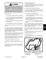
Page 44: ...se 17 1 2 12 13 14 7 6 8 9 4 16 5 15 11 11 10 30 to 50 in lb 3 4 to 5 6 N m Antiseize Lubricant 3 3 Illustration from machine with serial number below 312000000 shown CAUTION The muffler and exhaust manifold may be hot Avoid possible burns allow exhaust system to cool before working on the engine Fuel Tank Removal Fig 6 1 Park machine on a level surface disengage and low er cutting units move func...

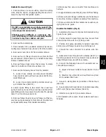
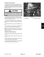
Page 45: ...elbow fitting on front of tank 7 Remove the fuel tank from the machine 8 If necessary remove fuel supply hose from shut off valve 9 If necessary remove shut off valve and fitting as sembly from fuel tank Fig 7 The nut and fitting have left hand threads Fuel Tank Installation Fig 6 1 Install fitting assembly and shut off valve into fuel tank if they were removed from tank Fig 7 The nut and fitting ...

Page 46: ...d 11 Receptacle 2 used 12 Cap screw 4 used 13 Flat washer 4 used 14 R clamp 15 Screen 16 Flange head screw 12 used 17 Lock nut 4 used 18 Flange head screw 4 used 19 Front shroud 20 Flange nut 12 used 21 Lower radiator hose 22 Upper radiator hose 23 Breather hose to thermostat 24 Overflow hose to overflow tank 25 Fuel pump 15 2 1 16 3 17 4 18 20 20 16 16 16 16 20 20 6 8 9 10 11 13 7 12 14 19 5 6 8 ...

Page 47: ...h r clamps item 7 on front shroud item 19 9 Remove flange head screw and flange nut that se cure fuel pump assembly to front shroud Position fuel pump assembly away from radiator assembly 10 Disconnect fan wire connector from machine wire harness 11 Support radiator assembly to prevent it from falling 12 Remove four 4 flange nuts that secure front shroud to machine Remove radiator assembly from ma...

Page 48: ...Greensmaster 3420 Page 4 14 Diesel Engine Starter Motor Figure 9 1 Starter motor 2 Flywheel plate 3 Bell housing 4 Cap screw 2 used 5 Lock washer 2 used 6 Nut 2 used 2 1 3 6 5 4 ...

Page 49: ...l all wires at starter solenoid for assembly pur poses Disconnect machine wires from starter solenoid posts 4 Support starter motor to prevent it from shifting or fal ling 5 Remove two 2 cap screws that secure starter motor to engine Remove starter motor from machine NOTE Refer to the Kubota Workshop Manual Diesel Engine SM E3B Series for information on starter motor service procedures Starter Mot...

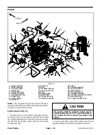
Page 50: ...4 used 26 Lock washer ground connection 27 Rear engine mount 28 R clamp air intake hose 19 20 21 22 22 23 24 26 25 27 28 18 NOTE This suggested engine removal procedure al lows the hydraulic pump bell housing and generator as sembly to remain in the machine Engine Removal Fig 11 1 Park machine on a level surface disengage and low er cutting units move functional control lever to neutral N engage p...

Page 51: ...rom engine 10 Disconnect wire harness connectors from engine components NOTE Before disconnecting wire harness connectors label all electrical leads for assembly purposes A Negative battery cable B Wire harness ground C Fuel stop solenoid Fig 13 D Glow plug bus Fig 13 E Alternator connector and stud Fig 14 F Temperature sender Fig 13 G Oil pressure switch near oil filter Fig 14 CAUTION Support the...

Page 52: ...ng the engine 15 Slowly move the engine assembly away from the bell housing to allow the pump coupling to slide out of the en gine coupling flange Fig 17 Once the engine has cleared the pump coupling carefully remove the engine from the machine 16 If required remove engine support item 23 from en gine 17 If required remove generator drive pulley and cou pling flange from engine flywheel Fig 18 Eng...

Page 53: ...allation in this sec tion 12 Install air cleaner to machine see Air Cleaner Instal lation in this section Make sure that all hose clamps are properly tightened 13 Connect all electrical harness connectors to engine using labels placed during engine removal 14 Insert fuel supply hose and fuel return hose through grommets in engine support on front of engine Remove plugs placed during engine removal...

Page 54: ...Greensmaster 3420 Page 4 20 Diesel Engine This page is intentionally blank ...

Page 55: ...Steering Valve Test 42 ADJUSTMENTS 44 Adjust Manifold Relief Valves 44 Adjust Traction Control Assembly 45 SERVICE AND REPAIRS 46 General Precautions for Removing and Installing Hydraulic System Components 46 Flush Hydraulic System 47 Filtering Closed Loop Traction Circuit 48 Hydraulic System Start up 49 Gear Pump 50 Gear Pump Service 52 Piston Traction Pump Neutral Assembly 54 Piston Traction Pum...

Page 56: ...Greensmaster 3320 3420 Hydraulic System Page 5 2 This page is intentionally blank ...

Page 57: ...bar Reverse 3000 PSI 207 bar Front Wheel Motors Orbital rotor motor Parker TF Series Displacement per revolution 10 3 in3 169 cc Rear Wheel Motor Optional 3WD Kit Orbital rotor motor Parker TG Series Displacement per revolution 20 6 in3 337 cc Power Steering Valve Hydrostatic Steering Unit Sauer Danfoss Type OSPMS Displacement per revolution 4 5 in3 74 cc Steering Lift Circuit Relief Pressure 1160...

Page 58: ...roce dure and hydraulic oil recommendations 1 Hydraulic reservoir 2 Fuel tank Figure 1 2 1 Pushing Traction Unit In case of emergency your Greensmaster can be pushed for a very short distance However Toro does not recommend this as a standard procedure 1 Make sure that engine is not running 2 Locate by pass valve on piston traction pump Fig 2 Rotate by pass valve so slot is vertical IMPORTANT Do n...

Page 59: ...ree 3 wheel motors are included if machine is equipped with optional 3WD kit If a component in the traction circuit should fail de bris and contamination from the failed component will circulate throughout the traction circuit This contamina tion can damage other components in the circuit so it must be removed to prevent additional component fail ure The recommended method of removing traction cir...

Page 60: ... the hose Use two wrenches hold the hose straight with one wrench and tighten the hose swivel nut onto the fit ting with the other wrench see Hydraulic Hose and Tube Installation in this section If the hose has an el bow at one end tighten the swivel nut on that end before tightening the nut on the straight end of the hose For additional hydraulic hose information refer to Toro Service Training Bo...

Page 61: ... in the Torque Specifica tions section of Chapter 2 Product Records and Main tenance 5 If a torque wrench is not available or if space at the swivel nut prevents use of a torque wrench an alternate method of assembly is the Flats From Wrench Resist ance F F W R method Fig 2 A Using a wrench tighten the swivel nut onto the fit ting until light wrench resistance is reached approxi mately 30 in lb B ...

Page 62: ...ords and Maintenance to determine necessary con version information 5 If a torque wrench is not available or if space at the port prevents use of a torque wrench an alternate meth od of assembly is the Flats From Finger Tight F F F T method A Install the fitting into the port and tighten it down full length until finger tight B If port material is steel tighten the fitting to the listed F F F T If...

Page 63: ...ith a wrench and use a torque wrench to tighten the fitting to the rec ommended installation torque shown in Figure 8 This tightening process will require the use of an offset wrench e g crowfoot wrench Use of an offset wrench will affect torque wrench calibration due to the effective length change of the torque wrench Tightening torque when using a torque wrench with an offset wrench will be lowe...

Page 64: ...R A B A B 33 1 44 110 150 PSI L R OR2 OR3 028 G1 G1 G2 BREATHER A B OR1 037 B A LEAK DETECTOR VOLUME EXPANSION TANK LEAK DETECTOR KIT OUT IN TOP PORT BOTTOM PORT BACK PORT C1 S4 S1 FORWARD OIL FILTER JOINT END STEERING CYLINDER 1160 VALVE PSI POWER STEERING HYDROSTAT 4 5 BYPASS VALVE 1 9 GPM 70 100 MOW 6 7 GPM AT 3 8 MPH TRANSPORT 17 5 GPM AT 10 MPH PSI OPTIONAL 3WD FRONT PORT 10 3 20 6 3000 PSI P...

Page 65: ...Greensmaster 3320 3420 Hydraulic System Page 5 11 This page is intentionally blank Hydraulic System ...

Page 66: ... PORT BALL 3000 PSI 4 0 GPM 10 3 RIGHT A B A B 33 1 44 110 150 PSI L R OR2 OR3 028 G1 G1 G2 BREATHER A B OR1 037 B A LEAK DETECTOR VOLUME EXPANSION TANK LEAK DETECTOR KIT OUT IN TOP PORT BOTTOM PORT BACK PORT C1 S4 S1 FORWARD JOINT END STEERING CYLINDER 1160 VALVE PSI POWER STEERING HYDROSTAT 4 5 BYPASS VALVE 1 9 GPM 70 to MOW 6 7 GPM AT 3 8 MPH TRANSPORT 17 5 GPM AT 10 MPH PSI OPTIONAL 3WD FRONT ...

Page 67: ...raction pedal so complete pump swash rotation is possible Forward The piston traction pump is driven directly by the en gine The hydraulic traction circuit acts essentially as a closed loop Taking its suction directly from the return side of the wheel motors of the traction circuit the piston pump supplies oil flow to the wheel motors through the supply side of the traction circuit With the engine...

Page 68: ...1 037 EXPANSION TANK LEAK DETECTOR KIT OUT IN S4 S1 JOINT END STEERING CYLINDER 1160 VALVE PSI POWER STEERING 4 5 25 PSI 028 LIFT CONTROL MANIFOLD RIGHT FRONT 3 LEFT FRONT 2 Extend to Lower Extend to Raise CENTER 1 Extend to Lower ENGINE GEAR C 3000 PSI 4 0 GPM 10 3 RIGHT A B A B 33 1 44 110 150 PSI G1 G2 A B B A TOP PORT BOTTOM PORT BACK PORT C1 FORWARD HYDROSTAT BYPASS VALVE 1 9 GPM 70 to MOW 6 ...

Page 69: ... the joystick is moved to the lower position the Toro Electronic Controller TEC energizes all of the lift control manifold solenoid valves for approximately three 3 seconds This time frame ensures that the cutting units will be fully lowered to allow them to float during op eration The controller also provides a short delay in en ergizing solenoid valve S4 which delays the lowering of the center c...

Page 70: ... LEAK DETECTOR KIT OUT IN S4 S1 JOINT END STEERING CYLINDER 1160 VALVE PSI POWER STEERING 4 5 25 PSI 028 LIFT CONTROL MANIFOLD RIGHT FRONT 3 LEFT FRONT 2 Extend to Lower Extend to Raise CENTER 1 Extend to Lower ENGINE GEAR C 3000 PSI 4 0 GPM 10 3 RIGHT A B A B 33 1 44 110 150 PSI G1 G2 A B B A TOP PORT BOTTOM PORT BACK PORT C1 FORWARD HYDROSTAT BYPASS VALVE 1 9 GPM 70 to MOW 6 7 GPM AT 3 8 MPH TRA...

Page 71: ...the lift control manifold oil filter and to the traction charge circuit Flow in excess of charge circuit needs then returns to the gear pump input Raise Cutting Units When the joystick is moved to the raise position the Toro Electronic Controller TEC energizes lift control man ifold solenoid valves S1 S3 and S4 for approximately three 3 seconds This time frame ensures that the cut ting units will ...

Page 72: ... 10 3 RIGHT A B A B 33 1 44 110 150 PSI L R OR2 OR3 028 G1 G1 G2 BREATHER A B OR1 037 B A EXPANSION TANK LEAK DETECTOR KIT OUT IN TOP PORT BOTTOM PORT BACK PORT C1 S4 S1 FORWARD JOINT END STEERING CYLINDER 1160 VALVE PSI POWER STEERING HYDROSTAT 4 5 BYPASS VALVE 1 9 GPM 70 to MOW 6 7 GPM AT 3 8 MPH TRANSPORT 17 5 GPM AT 10 MPH PSI OPTIONAL 3WD FRONT PORT 10 3 20 6 3000 PSI PUMP 25 PSI 028 LIFT CON...

Page 73: ...tional to the amount of the turning on the steering wheel Fluid leaving the cylinder flows back through the spool valve out steering valve port T and then to the traction charge circuit The power steering valve returns to the neutral position when turning is complete Left Turn When a left turn is made with the engine running the turning of the steering wheel positions the power steer ing valve spo...

Page 74: ...Number TOR47009 Figure 12 Hydraulic Tester Pressure and Flow This tester requires O ring Face Seal ORFS adapter fittings for use on this machine see Hydraulic Test Fit ting Kit TOR4079 in this section 1 INLET HOSE Hose connected from the system cir cuit to the inlet side of the hydraulic tester 2 LOAD VALVE A simulated working load is created in the circuit by turning the valve to restrict flow 3 ...

Page 75: ...flow in the operating circuit with a gauge rated from 4 to 40 GPM 20 to 150 LPM Toro Part Number AT40002 NOTE This tester does not include hydraulic hoses see Hydraulic Hose Kit TOR6007 below Figure 14 Hydraulic Hose Kit This kit includes hydraulic fittings and hoses needed to connect 40 GPM hydraulic tester AT40002 or high flow hydraulic filter kit TOR6011 to machine hydraulic trac tion system co...

Page 76: ...cing a failed traction circuit component e g piston traction pump or wheel motor the high flow hy draulic filter can be installed in the traction circuit The filter will ensure that contaminates are removed from the closed loop and thus do not cause additional compo nent damage Toro Part Number TOR6011 NOTE This kit does not include hydraulic hoses see Hydraulic Hose Kit TOR6007 above NOTE Replace...

Page 77: ...e effi ciency of a hydraulic motor by restricting the outlet flow from the motor and measuring leakage from the case drain line while the motor is pressurized by the hydraulic system Toro Part Number TOR4077 Figure 19 Wheel Hub Puller The wheel hub puller allows safe removal of the wheel hub from the shaft of wheel motors Toro Part Number TOR4097 Figure 20 Hydraulic System ...

Page 78: ...are missing or damaged Hydraulic fluid foams Oil level in reservoir is low Hydraulic system has wrong type of oil The gear pump suction line has an air leak Hydraulic system operates hot Oil level in reservoir is low Oil is contaminated or too light Parking brake is applied or incorrectly adjusted Piston pump by pass valve is open or defective Charge pressure is low see Charge Relief Valve Pressur...

Page 79: ... direction Parking brake is applied or incorrectly adjusted Oil level in reservoir is low other hydraulic systems also affected Piston pump by pass valve is open Charge pressure is low see Charge Relief Valve Pressure Test in the Testing section of this chapter Relief valve s in piston traction pump are leaking or damaged Wheel motor s is worn or damaged see Wheel Motor Efficiency Test in the Test...

Page 80: ...d valve not shifting to its energized position Lift cylinder s leak internally Spool in power steering valve is sticking see Power Steering Valve Test in the Testing section of this chapter Gear pump is worn or damaged steering and charge circuits af fected as well see Steering Lift Circuit Gear Pump Flow Test in the Testing section of this chapter Front cutting units 2 and 3 raise but will not st...

Page 81: ...the Testing section of this chap ter Backlash results when turning steer ing wheel Cardan shaft fork in power steering valve is worn or broken Leaf springs in power steering valve are worn or broken Splines on the steering column are worn Rear wheel shimmies when the steering wheel is turned Air is in the steering cylinder Rear steering fork assembly is worn or damaged The steering wheel can be tu...

Page 82: ...omponents Always keep in mind the need for cleanliness when working on hy draulic equipment Contamination will cause excessive wear of components 2 To prevent hydraulic system contamination put clean metal caps or plugs on any hydraulic lines left open or exposed during testing or removal of compo nents 3 The engine must be in good operating condition En gine speed will affect test accuracy Check ...

Page 83: ...th relief valves for both the forward and reverse direction Due to engine output it is unlikely that traction pressure will reach relief valve settings If however a piston pump relief valve is leak ing or otherwise faulty traction performance would be affected 4 For problems with the steering and lift lower circuit consider performing one or more of the following tests A Steering Lift Relief Valve...

Page 84: ...roximately ten 10 minutes 2 Park machine on a level surface with the cutting units lowered Make sure engine is off and the parking brake is engaged Make sure the hydraulic tank is full CAUTION Prevent personal injury and or damage to equip ment Read all WARNINGS CAUTIONS and Pre cautions for Hydraulic Testing at the beginning of this section 3 Thoroughly clean junction of hydraulic hose and hy dra...

Page 85: ...Once dynamic charge pressure has been deter mined move throttle to low idle speed and shut off engine Record test results E The charge pressure should drop no more than 20 from no load charge pressure measured in step 9 above e g if charge pressure in step 9 is 125 PSI 8 6 bar charge pressure in forward or reverse should be more than 100 PSI 6 9 bar F If charge pressure is good under no load but d...

Page 86: ...PORT BACK PORT C1 HYDROSTAT BYPASS VALVE 1 9 GPM 70 to MOW 6 7 GPM AT 3 8 MPH TRANSPORT 17 5 GPM AT 10 MPH PSI OPTIONAL 3WD FRONT PORT 10 3 20 6 3000 PSI PUMP 100 MOTOR LEFT MOTOR HYDRAULIC RESERVOIR FROM POWER STEERING AND LIFT CONTROL VALVES FROM STEERING VALVE TO POWER TESTER UPPER PUMP PISTON FITTING UPPER PUMP PISTON FITTING FRONT FRONT PUMP FROM GREENSMASTER 3320 PUMP FROM GREENSMASTER 3420 ...

Page 87: ...e Special Tools in this chapter to connect tester to machine Make sure that fit ting and hose connections are properly tightened Also make sure the flow control valve on tester is fully open 7 After installing tester start engine and run at low idle speed Check for hydraulic leakage and correct before proceeding with test 8 Move functional lever to the transport position CAUTION Wheels off the gro...

Page 88: ...IC RESERVOIR TO UPPER PUMP PISTON FITTING FRONT NOTE Over a period of time a wheel motor can wear internally A worn motor may by pass oil to its case drain causing the motor to be less efficient Eventually enough oil loss will cause the wheel motor to stall under heavy load conditions Continued operation with a worn inefficient motor can generate excessive heat cause damage to seals and other comp...

Page 89: ...so engine is running at high idle speed Make sure that functional control lever is in the transport position 13 Slowly push traction pedal in forward direction until 1000 PSI 69 bar is displayed on the tester pressure gauge Make sure that wheel motor being tested is not rotating 14 Wheel motor internal leakage will be shown on flow meter Flow should be less than 1 5 GPM 5 7 LPM for the tested whee...

Page 90: ... B A TOP PORT BOTTOM PORT BACK PORT C1 S4 FORWARD JOINT END STEERING CYLINDER 1160 VALVE PSI POWER STEERING HYDROSTAT 4 5 BYPASS VALVE 1 9 GPM 70 to MOW 6 7 GPM AT 3 8 MPH TRANSPORT 17 5 GPM AT 10 MPH PSI OPTIONAL 3WD FRONT PORT 10 3 20 6 3000 PSI 25 PSI 028 RIGHT FRONT 3 LEFT FRONT 2 Extend to Lower Extend to Raise CENTER 1 Extend to Lower LIFT CONTROL MANIFOLD 100 MOTOR LEFT MOTOR PRESSURE GAUGE...

Page 91: ...Check for hy draulic leakage and correct before proceeding with test 8 Move throttle so engine is running at high idle speed CAUTION While measuring steering lift relief valve pres sure do not allow circuit pressure to exceed 1400 PSI 82 8 bar 9 Watch the pressure gauge and move the joystick to the raise position Momentarily hold the joystick with the cutting units fully raised causing the relief ...

Page 92: ...1 037 B A TOP PORT BOTTOM PORT BACK PORT C1 S4 FORWARD JOINT END STEERING CYLINDER 1160 VALVE PSI POWER STEERING HYDROSTAT 4 5 BYPASS VALVE 1 9 GPM 70 to MOW 6 7 GPM AT 3 8 MPH TRANSPORT 17 5 GPM AT 10 MPH PSI OPTIONAL 3WD FRONT PORT 10 3 20 6 3000 PSI 25 PSI 028 RIGHT FRONT 3 LEFT FRONT 2 Extend to Lower Extend to Raise CENTER 1 Extend to Lower LIFT CONTROL MANIFOLD 100 MOTOR LEFT MOTOR PRESSURE ...

Page 93: ...test 7 Move throttle so engine is running at high idle speed NOTE The lower cutting units function is electrically timed and automatically turns off after approximately three 3 seconds While performing this hydraulic test if relief pressure cannot be determined within the LOW ER function three 3 second timeframe repeat this test procedure 8 Watch pressure gauge carefully while moving the joystick ...

Page 94: ... G1 G2 A B OR1 037 B A TOP PORT BOTTOM PORT BACK PORT C1 S4 FORWARD JOINT END STEERING CYLINDER 1160 VALVE PSI POWER STEERING HYDROSTAT 4 5 BYPASS VALVE 1 9 GPM 70 to MOW 6 7 GPM AT 3 8 MPH TRANSPORT 17 5 GPM AT 10 MPH PSI OPTIONAL 3WD FRONT PORT 10 3 20 6 3000 PSI 25 PSI 028 RIGHT FRONT 3 LEFT FRONT 2 Extend to Lower Extend to Raise CENTER 1 Extend to Lower LIFT CONTROL MANIFOLD 100 MOTOR LEFT MO...

Page 95: ... the disconnected hose Also make sure flow control valve on the tester is fully open 5 Make sure that traction pedal and joystick are in neu tral and the parking brake is engaged 6 Start engine and run at low idle speed Check for hy draulic leakage and correct before proceeding with test 7 Move throttle so engine is running at high idle speed IMPORTANT Do not fully restrict oil flow through tester...

Page 96: ...3320 3420 Hydraulic System Page 5 42 Power Steering Valve Test P T E BALL JOINT L R END PORT 1160 VALVE PSI POWER STEERING 4 5 STEERING CYLINDER PLUG CYLINDER ROD FULLY EXTENDED ROTATED FOR LEFT TURN STEERING WHEEL ...

Page 97: ...eering wheel must be able to turn with no more than 45 in lb 5 1 N m of torque 6 If either of these performance tests indicate a steer ing problem determine if the steering cylinder is faulty using the following procedure A Park machine on a level surface with the cutting units lowered and off Make sure engine is off and the parking brake is engaged B Turn the steering wheel all the way to the lef...

Page 98: ...njury may result Always install and tighten the cap be fore pressurizing the system 1 Locate relief valve on control manifold 2 Remove cap on relief valve with an allen wrench 3 To increase pressure setting turn the adjustment socket on the valve in a clockwise direction A 1 8 turn on the socket will make a measurable change in relief pressure 4 To decrease pressure setting turn the adjustment soc...

Page 99: ...al locked in place the pedal should be at a right angle 90o to platform Fig 29 If neces sary adjust location of ball joint on neutral lock cable to allow correct angle of pedal In the neutral position there should be no tension on the traction cable If cable is adjusted too tight machine could creep when in the neutral position Adjust jam nuts on traction cable to reduce tension on cable An eccent...

Page 100: ...stallation after repairs are completed 5 Note the position of hydraulic fittings especially el bow fittings on hydraulic components before removal Mark parts if necessary to make sure they will be aligned properly when reinstalling hydraulic hoses and tubes After Repair or Replacement of Components 1 Check oil level in the hydraulic reservoir and add cor rect oil if necessary Drain and refill hydr...

Page 101: ... Use only hydraulic fluids including biodegrad able fluid specified in the Traction Unit Operator s Manual Other fluids could cause system damage 6 Connect all hydraulic hoses and lines that were dis connected prior to system draining see Hydraulic Hose and Tube Installation in the General Information section of this chapter 7 Fill hydraulic reservoir with new hydraulic oil 8 Disconnect appropriat...

Page 102: ...off the ground and rotating dur ing this procedure Make sure machine is well supported so it will not move and accidentally fall to prevent injuring anyone around machine IMPORTANT While engaging the traction circuit monitor the indicator on the high flow hydraulic fil ter If the indicator should show red either reduce pressure on the traction pedal or reduce engine speed to decrease hydraulic flo...

Page 103: ...gasoline engine disconnect both spark plug wires from spark plugs B On machines with diesel engine disconnect wire harness electrical connector from the engine fuel stop solenoid 8 Turn ignition key switch and engage starter for ten 10 seconds to prime hydraulic pumps Return ignition switch to off and wait one 1 minute to allow starter to cool Repeat step a second time 9 Reconnect engine electrica...

Page 104: ...Hydraulic System Components in this section 1 Park machine on a level surface engage the parking brake lower the cutting units and stop the engine Re move key from the ignition switch 2 Thoroughly clean hydraulic hose ends and fittings on gear pump to prevent hydraulic system contamination 3 Label all hose connections on gear pump for as sembly purposes 4 Clamp gear pump suction inlet hose to prev...

Page 105: ...Position gear pump to the piston traction pump so that the pump inlet is facing up 5 Secure gear pump to the piston pump with two 2 socket head screws and flat washers Torque screws from 27 to 31 ft lb 37 to 42 N m 6 Lubricate and place new O rings onto gear pump hydraulic fittings Install fittings into pump openings making sure that fitting orientation is as noted during re moval Tighten fittings...

Page 106: ...n and seal replacement only Individual gears hous ings and thrust plates are not available separately If internal components are worn or damaged the gear pump must be replaced as a complete assembly 1 Plug pump ports and thoroughly clean exterior of pump with cleaning solvent Make sure work area is clean 2 Use a marker to make diagonal line across the front cover housing and end cover for assembly...

Page 107: ...1 Replace the entire pump assembly if any internal pump components are excessively worn scored or damaged Gear Pump Assembly Fig 35 NOTE When assembling the gear pump check the marker line on front cover housing and end cover to make sure the parts are properly aligned during as sembly 1 Apply clean hydraulic oil to all pump parts before as sembling 2 Install new seal into front cover Fig 37 A Pre...

Page 108: ... ball joint 21 Cap screw 22 Washer 23 Flange nut 24 Flange nut 25 Cap screw 26 Traction control cable 27 Cap screw 2 used diesel 28 Muffler bracket diesel 29 Piston traction pump 30 Key Figure 38 200 to 250 in lb 23 to 28 N m Antiseize Lubricant 5 16 3 6 22 17 23 2 1 18 10 14 11 7 19 15 12 21 9 27 25 20 4 8 26 17 17 13 28 27 24 29 Antiseize Lubricant FRONT RIGHT PUMP ASSEMBLY FROM GREENSMASTER 342...

Page 109: ...ring to the pump neutral assembly A If cable support item 1 was removed from pump apply Loctite 242 or equivalent to threads of screws that secure support to pump B If plate item 2 was removed from pump trunnion shaft make sure that both trunnion shaft and plate bore are thoroughly cleaned before installing plate to shaft Secure plate to trunnion shaft with flat washer item 3 and cap screw item 4 ...

Page 110: ...p screw 22 Flange nut 23 Cap screw 2 used 24 Flat washer 2 used 25 O ring 26 Traction control cable 21 20 26 22 23 16 12 24 25 8 17 14 13 15 18 19 16 5 FRONT RIGHT PUMP ASSEMBLY FROM GREENSMASTER 3320 SHOWN 6 9 4 3 2 10 11 13 17 7 1 14 Antiseize Lubricant 27 to 31 ft lb 37 to 42 N m NOTE The piston traction and gear pump assembly can be removed from the machine with the neutral as sembly attached ...

Page 111: ...rting fasteners to pre vent it from falling and causing damage or per sonal injury 8 Support pump assembly to prevent it from falling 9 Remove two 2 cap screws item 23 and flat wash ers item 24 that secure pump assembly to pump mount Slide pump assembly away from the pump mount and coupling attached to engine Remove pump from machine 10 If necessary remove coupling from pump shaft Greensmaster 332...

Page 112: ...the General Information section of this chapter 6 Insert coupling on pump shaft into coupling attached to engine and slide pump assembly to pump mount Se cure pump assembly to pump mount with two 2 cap screws item 23 and flat washers item 24 7 Remove plugs that were placed during disassembly from hydraulic fittings and hoses 8 Using labels placed during pump removal lubricate new O rings and conne...

Page 113: ...Greensmaster 3320 3420 Hydraulic System Page 5 59 This page is intentionally blank Hydraulic System ...

Page 114: ...te 11 Rotating kit 12 Gasket 13 Valve plate 14 Bearing 15 Dowel pin 16 Back plate 17 O ring 18 Relief valve 19 Bypass valve 20 O ring 21 Cap screw 2 used 22 Cap screw 2 used 23 Coupler 24 Roll pin 25 Cover plate 26 Swash plate insert 27 Shaft seal 28 Washer 3 used per plate 29 Housing 30 Retaining ring 31 Bearing race 32 Thrust bearing 33 Washer 34 Shaft seal 35 Retaining ring 36 Retaining ring 37...

Page 115: ...y that traction pressure will reach relief valve settings If however a pump relief valve is leaking or otherwise faulty traction performance would be affected IMPORTANT The shim kit item 7 is used to replace the original crush ring not shown in the cover plate item 25 If the swash plate item 10 cover plate item 25 or housing item 29 is replaced during ser vicing the old crush ring must be replaced...

Page 116: ... cover plate in the same location that the crush ring was removed from 4 Assemble housing sub assembly consisting of the housing swash plate bearing cone bearing cup and cover plate see Eaton Medium Duty Piston Pump Re pair Information Model 70160 Variable Displacement Piston Pump at the end of this chapter 5 Install washers and cap screws to the cover plate and housing Torque cap screws to 29 ft ...

Page 117: ...Greensmaster 3320 3420 Hydraulic System Page 5 63 This page is intentionally blank Hydraulic System ...

Page 118: ...e Re move key from the ignition switch CAUTION Before continuing further read and become fa miliar with General Precautions for Removing and Installing Hydraulic System Components in this section 2 Loosen but do not remove lug nuts item 9 and lock nut item 7 Loosen lock nut at least two 2 turns 3 Chock front and rear of wheels not being lifted to pre vent the machine from moving Lift front wheel o...

Page 119: ... from wheel motor ports Lubricate and place new O rings onto fittings Install fittings into motor openings making sure that fitting orientation is as noted during removal Tighten fittings see Hydraulic Fit ting Installation in the General Information section of this chapter 3 Remove caps from disconnected hydraulic lines 4 Lubricate and position new O rings to fittings on wheel motor Use labels pl...

Page 120: ...lic fitting 2 used 10 Hydraulic tube 11 Hydraulic tube 12 Tube clamp 2 used 13 Cover plate 14 Cap screw 15 Hydraulic hose 16 Hydraulic hose 17 Hose guide 18 Rear fork 19 O ring 20 Cap screw 2 used 21 O ring 22 Wheel stud 4 used 23 Woodruff key Figure 47 FRONT RIGHT 75 ft lb 101 N m 21 4 13 1 10 11 3 17 2 6 14 20 9 12 8 5 7 15 16 18 19 19 19 22 75 ft lb 101 N m 250 to 400 ft lb 339 to 540 N m 65 to...

Page 121: ... and motor plate item 2 from machine 12 If fitting removal from wheel motor is necessary mark fitting orientation to allow correct assembly Re move hydraulic fittings and O rings from motor Discard removed O rings Rear Wheel Motor Optional 3WD Installation Fig 47 1 If fittings were removed from rear wheel motor lubri cate and place new O rings onto motor fittings Install fittings into motor openin...

Page 122: ...he stator The right wheel motor s has a reverse timed manifold NOTE If machine is equipped with optional 3WD kit the rear wheel motor has the same basic construction as the front wheel motors IMPORTANT DO NOT interchange wheel motors on machine i e do not put RH motor on left side of ma chine If necessary use parts catalog and part num ber on wheel motor to identify RH and LH motors NOTE For wheel...

Page 123: ...Greensmaster 3320 3420 Hydraulic System Page 5 69 This page is intentionally blank Hydraulic System ...

Page 124: ...ose 8 Flange nut 9 Clevis pin 3 used 10 Pivot pin 11 Hydraulic hose 12 Hydraulic hose 13 Flange head screw 14 O ring 15 90o hydraulic fitting 2 used 16 O ring 17 Washer 3 used 18 Rue ring 3 used 19 Hydraulic hose 20 Hydraulic hose 21 Straight hydraulic fitting 3 used 22 45o hydraulic fitting 23 Cutting unit suspension Figure 49 11 12 17 18 2 6 8 9 10 13 1 5 7 14 15 16 19 20 4 2 4 3 6 21 22 15 21 1...

Page 125: ...ect assembly Remove hydraulic fittings and O rings from cylinder Discard removed O rings 9 Inspect threads and sealing surfaces of fittings and lift cylinder ports Replace components if damage is found Lift Cylinder Installation Fig 49 1 If fittings were removed from lift cylinder lubricate and place new O rings onto fittings Install fittings into cylinder ports making sure that fitting orientatio...

Page 126: ...ad seal 11 Dust seal 12 Head 13 Shaft Figure 50 FRONT LIFT CYLINDER SHOWN 40 ft lb 54 N m 2 3 6 8 9 10 11 1 5 7 12 4 2 3 6 8 9 10 11 13 1 5 7 12 4 13 NOTE The center lift cylinder 1 cutting unit has less stroke than the front lift cylinders 2 and 3 cutting units which are identical Service procedures for all lift cylinders used on Greensmaster TriFlex Hybrid ma chines are the same ...

Page 127: ... Lint in a hydraulic system will cause damage 8 Carefully inspect internal surface of barrel for dam age deep scratches out of round etc Inspect shaft head and piston for evidence of excessive scoring pit ting or wear Replace entire cylinder if internal compo nents are found to be worn or damaged Assembly Fig 50 1 Make sure all lift cylinder parts are clean before as sembly 2 Coat new seal kit com...

Page 128: ... 90o hydraulic fitting 10 O ring 11 Hydraulic hose 12 Hydraulic hose 13 Tee fitting 14 45o hydraulic fitting 15 Hydraulic hose 16 Flange head screw 2 used 17 Hydraulic tube 18 Hydraulic tube 19 Hydraulic hose 20 Hydraulic hose 21 Hydraulic hose 22 Hydraulic hose 23 90o hydraulic fitting 24 O ring Figure 51 FRONT RIGHT 11 12 17 18 2 3 6 8 9 10 13 1 5 7 14 15 16 19 20 4 2 2 4 3 6 6 6 6 21 22 23 24 ...

Page 129: ...ne frame Remove manifold assembly from the machine IMPORTANT Before removing any hydraulic fitting from the hydraulic manifold make sure the position of fitting is observed and recorded to ensure proper fitting installation IMPORTANT A flow control orifice is placed be neath hydraulic fittings in lift control manifold ports C4 and C6 If either of these fittings is removed from the lift junction ma...

Page 130: ...Solenoid coil 8 Nut 9 Solenoid coil 3 used 10 Coil spacer 11 Nut 12 Relief valve port RV 13 Solenoid valve port S1 14 Solenoid valve port S3 15 Check valve port CV 16 45o hydraulic fitting 17 Orifice 0 037 port C2 25 ft lb 34 N m 60 in lb 6 7 N m 20 ft lb 27 N m UP VIEW FROM BELOW Figure 52 2 6 8 9 10 11 13 1 5 7 12 14 15 16 4 2 2 3 8 9 9 10 17 3 20 ft lb 27 N m 20 ft lb 27 N m 60 in lb 6 7 N m 20...

Page 131: ...ised as compo nents are loosened in manifold cutting units may drop unexpectedly NOTE The hydraulic manifold shown in Figure 52 uses several zero leak plugs These plugs have a tapered sealing surface on the plug head that is designed to re sist vibration induced plug loosening The zero leak plugs also have an O ring to provide a secondary seal If zero leak plug removal is necessary lightly rap the...

Page 132: ...the system CAUTION Use eye protection such as goggles when using compressed air 6 Clean cartridge valve using clean mineral spirits Submerge valve in clean mineral spirits to flush out con tamination Particles as fine as talcum powder can affect the operation of high pressure hydraulic valves If car tridge design allows use a wood or plastic probe to push the internal spool in and out 20 to 30 tim...

Page 133: ...Greensmaster 3320 3420 Hydraulic System Page 5 79 This page is intentionally blank Hydraulic System ...

Page 134: ...eering wheel 7 Button head screw 6 used 8 Tinnerman nut 6 used 9 Flange head screw 4 used 10 Power steering valve 11 Steering arm 12 Steering valve cover 13 Straight hydraulic fitting 2 used 14 Straight hydraulic fitting 3 used 15 Steering mount Figure 53 FRONT RIGHT 20 to 26 ft lb 28 to 35 N m 6 7 8 9 10 5 1 2 3 4 11 12 13 14 13 14 15 Antiseize Lubricant ...

Page 135: ...ontamination 9 Remove steering valve from machine 10 If necessary remove hydraulic fittings and O rings from power steering valve Discard removed O rings Installation Fig 53 1 If fittings were removed from power steering valve lubricate and place new O rings onto fittings Install fit tings into steering valve openings Tighten fittings see Hydraulic Fitting Installation in the General Information s...

Page 136: ...17 Cardan shaft 18 O ring 19 Distribution plate 20 Outer gearwheel 21 Inner gearwheel 22 End cover 23 O ring 5 used 24 Cap screw 5 used 25 Spring set 26 Ball stop 27 Ball 28 P port 29 L port Figure 55 v 10 16 11 12 13 14 15 17 18 2 1 3 4 8 5 9 6 19 7 20 18 18 21 22 23 24 20 to 24 ft lb 27 to 33 N m 11 26 27 25 29 28 NOTE For service of the power steering valve see the Sauer Danfoss Steering Unit T...

Page 137: ...Greensmaster 3320 3420 Hydraulic System Page 5 83 This page is intentionally blank Hydraulic System ...

Page 138: ...nd stop the engine Re move key from the ignition switch CAUTION Before continuing further read and become fa miliar with General Precautions for Removing and Installing Hydraulic System Components in this section 2 Operate all hydraulic controls to relieve hydraulic system pressure 3 To allow easier access to steering cylinder raise and support tank mount plate assembly hydraulic reservoir fuel ta...

Page 139: ...ll joints and cylinder attachment bores on ma chine 4 Place cylinder spacer item 10 onto cylinder barrel ball joint 5 Insert ball joints of cylinder into attachment points on frame and rear fork assembly 6 Secure both steering cylinder ball joints to machine with two 2 jam nuts item 4 Install first jam nut and torque from 60 to 80 ft lb 82 to 108 N m Then while holding first jam nut with wrench ti...

Page 140: ...ring Cylinder Service 1 Shaft 2 Collar 3 Head ball joint end 4 Dust seal 5 Shaft seal 6 O ring and backup ring 7 Wear ring 8 Piston seal 9 Dowel pin 10 Piston 11 O ring 12 Barrel 13 Head non ball joint end Figure 58 2 3 6 8 9 10 11 13 1 5 7 12 4 2 4 5 6 7 ...

Page 141: ... system will cause damage 11 Carefully inspect internal surface of barrel for dam age deep scratches out of round etc Inspect shaft both heads and piston for evidence of excessive scor ing pitting or wear Replace entire steering cylinder if in ternal components are damaged Assembly Fig 58 1 Put a coating of clean hydraulic oil on all new seals back up rings wear rings and O rings 2 Install new sha...

Page 142: ... 11 16 17 18 15 30 to 50 in lb 3 4 to 5 6 N m 6 19 20 21 22 23 27 1 12 13 14 70 to 80 ft lb 95 to 108 N m 30 to 38 ft lb 41 to 51 N m 30 to 38 ft lb 41 to 51 N m Antiseize Lubricant 30 to 50 in lb 3 4 to 5 6 N m Antiseize Lubricant 17 to 21 ft lb 23 to 28 N m 18 30 to 38 ft lb 41 to 51 N m Illustration from diesel powered machine with serial number below 312000000 shown Removing Hydraulic Reservoi...

Page 143: ...ean solvent Inspect reservoir for leaks cracks or other damage Installing Hydraulic Reservoir Fig 59 IMPORTANT When installing tank cover and reser voir to machine do not over tighten cap screws Threads in reservoir may become damaged 1 Lubricate and place new O rings onto all removed fittings and plugs Install fittings and plugs into reservoir openings Use marks made during the removal process to...

Page 144: ...o barb fitting 2 used 22 Tank hose 23 Cap screw 2 used 24 Lock washer 2 used 25 Oil level sensor 26 O ring Figure 60 17 to 21 ft lb 23 to 28 N m 15 2 3 4 5 6 7 8 9 10 18 19 20 21 16 17 22 23 3 19 19 19 21 24 1 12 13 14 11 11 11 11 25 30 to 60 in lb 3 4 to 6 7 N m 110 to 140 in lb 12 5 to 15 8 N m 40 to 50 ft lb 55 to 67 N m 40 to 50 ft lb 55 to 67 N m 26 Antiseize Lubricant 30 to 50 in lb 3 4 to 5...

Page 145: ... can ister is attached to the leak detector tank Fig 62 See Fuel System Carbon Canister Serial Number Above 312000000 in the Service and Repairs section of Chap ter 3 Gasoline for information on disconnecting the canister 8 Remove leak detector tank assembly from machine 9 If necessary remove valve hose item 20 hydraulic fitting item 18 and breather assembly from leak detec tor tank Discard all re...

Page 146: ...c reservoir Threads in reservoir may become damaged 6 Secure leak detector tank to hydraulic reservoir with four spacers item 9 neoprene washers item 8 flat washers item 7 and cap screws item 6 Torque cap screws from 30 to 50 in lb 3 4 to 5 6 N m NOTE Monitor hydraulic fluid level in leak detector tank window As air is removed from the hydraulic circuit additional oil may have to be added to reser...

Page 147: ...Greensmaster 3320 3420 Hydraulic System Page 5 93 This page is intentionally blank Hydraulic System ...

Page 148: ...ulic fitting 15 O ring 16 Solenoid valve assembly 17 Cover 18 Straight barb fitting 19 Hose clamp 4 used 20 Valve hose 21 90o barb fitting 2 used 22 Tank hose 23 Cap screw 2 used 24 Lock washer 2 used 25 Oil level sensor Figure 63 17 to 21 ft lb 23 to 28 N m 30 to 50 in lb 3 4 to 5 6 N m 15 2 3 4 5 6 7 8 9 10 18 19 20 21 16 17 22 23 3 19 19 19 21 24 1 12 13 14 11 11 11 11 25 30 to 60 in lb 3 4 to ...

Page 149: ...dge Valve Service in this section A When installing cartridge valve torque valve 35 ft lb 47 N m B When installing solenoid coil apply a drop of Loc tite 242 or equivalent to threads of valve and torque nut 10 in lb 1 1 N m Installation Fig 63 1 If fittings were removed from solenoid valve man ifold lubricate and place new O rings onto fittings Install fittings into manifold openings Tighten fitti...

Page 150: ...Greensmaster 3320 3420 Hydraulic System Page 5 96 This page is intentionally blank ...

Page 151: ...2000000 45 Fuse Block Greensmaster 3420 with Serial Number Above 312000000 46 Electric Reel Drive System 48 Volt DC Fuses 47 Fusible Links 48 Hour Meter 49 Seat Switch 50 Neutral and Mow Switches 51 Parking Brake Switch 52 Joystick Raise and Lower Switches 53 Backlap Switch 54 Electric Reel Contactor 55 Reel Speed Potentiometer Serial Number Below 312000000 56 Toro Electronic Controller TEC 57 Hyd...

Page 152: ...omponents on Greensmaster Hybrid TriFlex machines is accom plished on two 2 CAN bus communication systems The CAN bus system reduces the number of electrical components and connections used on the machine and allows the number of wires in the wire harness to be re duced One of these CAN bus systems allows TEC controller communication between machine 12 volt components e g engine components InfoCen...

Page 153: ...its disconnect the cutting units from the electrical power supply by separating the cutting unit power dis connect couplers Fig 1 The couplers are located at the base of the rollover bar on the left side of the traction unit Connect the couplers together before operating the machine 1 Coupler 2 Stationary coupler Figure 1 1 2 Electrical Drawings The electrical schematic and wire harness drawings f...

Page 154: ...battery pack is composed of four 4 12 volt sealed batteries connected in series to achieve the necessary 48 VDC The batteries are included in the system to en sure that reels come up to speed quickly when initially engaged The batteries are also used as a buffer when the cutting reels are shut off As the cutting reels slow to a stop they generate electrical power that is absorbed by the battery pa...

Page 155: ...Greensmaster 3320 3420 Page 6 5 Electrical System This page is intentionally blank Electrical System ...

Page 156: ...evel sensor float is in raised position keeping alarm circuit open Figure 2 TANK SIGHT GAUGE SOLENOID VALVE open ALARM off OIL LEVEL SENSOR raised open MAIN HYDRAULIC TANK LEAK DETECTOR Normal Operation Warm Oil When ignition switch is turned ON solenoid valve closes During normal operation hydraulic fluid ex pands causing it to overflow into leak detector tank The oil level sensor stays in the ra...

Page 157: ...larm will sound and the console indicator light will illuminate after a one 1 second time delay NOTE During normal operation with cutting units low ered approximately 5 oz 148 ml of hydraulic fluid will leak before the oil level sensor float closes the alarm cir cuit and activates the alarm Figure 4 MAIN HYDRAULIC TANK LEAK DETECTOR TANK SIGHT GAUGE SOLENOID VALVE closed ALARM on lowered closed OI...

Page 158: ... communication con nector located under the operator seat to verify correct electrical functions of the Toro Electronic Controller TEC TEC inputs and outputs can be checked using the Diagnostic Display Toro Part Number for Hand Held Diagnostic Display 85 4750 Toro Part Number for Greensmaster 3320 3420 Overlay English 115 8227 NOTE Diagnostic Display overlays are available in several languages for...

Page 159: ...ver grease see TOR50547 above Toro Part Number 107 0392 Figure 9 Dielectric Lubricant Sealant Dielectric lubricant should be used to prevent corrosion of non sealed connection terminals To ensure com plete coating of terminals liberally apply lubricant to both component and wire harness connector plug con nector to component unplug connector reapply lubri cant to both surfaces and reconnect harnes...

Page 160: ... rotor removal to prevent component damage or personal injury 4 Turn threaded shaft with handle to remove generator rotor and cover from generator housing Support rotor to prevent it from falling during removal 5 Leave threaded shaft installed in same position in base plate for rotor installation purposes Generator Rotor Installation 1 Secure tool set base plate to generator housing with three 3 3...

Page 161: ...ge or personal injury 5 Turn threaded shaft with handle to remove rotor and motor cover from motor housing Support rotor to pre vent it from falling from housing during removal 6 Leave threaded shaft installed in same position in base plate for rotor installation purposes Cutting Reel Motor Rotor Installation 1 Secure tool set base plate to motor housing with four 4 of the cover screws 2 Make sure...

Page 162: ...h is initially turned to the RUN or START position The splash screen allows basic ma chine information to be reviewed After the splash screen has been on the InfoCenter for several seconds the main information screen will be displayed on the InfoCenter The splash screen can be used to identify hour meter reading machine battery voltage generator voltage and engine status If the fault log indicator...

Page 163: ...tional control lever is in the mow position The main information screen will include three 3 ar rows to the right of the coolant temperature whenever the cutting units are either raising up arrows or lower ing down arrows If an electrical machine fault occurs during machine op eration the InfoCenter fault indicator will blink to notify the operator Also the fault log indicator on the Info Center s...

Page 164: ...Center The faults will be identified by a fault number and when the fault occurred Faults that might occur on the machine are listed in Fault Codes in the Troubleshooting section of this chapter The InfoCenter fault log can be cleared by selecting the clear system faults menu item The cleared faults will be removed from the InfoCenter but will be retained in the TEC controller memory If a fault oc...

Page 165: ...ap identifies the number of hours that the ma chine has been operated with the cutting units engaged in the backlap position D Fan On identifies the number of hours that the ma chine has been operated with engine cooling fan en gaged D Over Temp identifies the number of hours that the engine has been operated with an excessive tempera ture The options listed for counts include the following D Preh...

Page 166: ...itches Qualifiers lists the joystick position Outputs indicate whether solenoid S1 is energized D S2 identifies machine requirements to allow hydrau lic lift control manifold solenoid coil S2 lower to be en ergized Inputs indicate the state of the joystick lower switch Qualifiers identify the three 3 second time frame to lower the cutting units Outputs indicate wheth er solenoid S2 is energized D ...

Page 167: ...ntroller InfoCenter reel motor controllers and generator controller The about screen also lists the CAN bus status To return to the main menu screen from the about screen press the back button left button Figure 22 About Model SN TEC 5001 04530 312000285 120 6320G 1 5 3 4 5 2 1 About menu 2 About items 3 Move to menu items 4 Choose menu item 5 Back button 3 Electrical System ...

Page 168: ...se delay lower delay tapoff time reel speed and backlap RPM unless settings have been protected Raise delay allows the adjustment of the delay of the center cutting unit when the cutting units are raised by the operator The factory default setting for the raise delay is 6 which is optimized for a 3 8 MPH mow speed Lower delay allows the adjustment of the delay of the center cutting unit when the c...

Page 169: ...Greensmaster 3320 3420 Page 6 19 Electrical System This page is intentionally blank Electrical System ...

Page 170: ...cated on the control panel Fig 25 When the ignition switch is moved to the RUN position and the machine electrical system is functioning pro perly the diagnostic light will be illuminated for approxi mately three 3 seconds and then will turn off The light should remain off during normal machine operation If the machine TEC controller detects an electrical sys tem malfunction fault during machine o...

Page 171: ...most re cent fault to the oldest fault If there are multiple faults in controller memory there will be a three 3 second pause between codes The fault codes will continually repeat after a five 5 second pause until the ignition key is turned off See Fault Codes in this section to identify faults that have occurred with a machine If there are no faults that have occurred within the last forty 40 hou...

Page 172: ...erator allow machine to cool down Note this fault IS NOT caused by a faulty sensor 1 7 1 cutting unit motor at zero 0 RPM for more than three 3 seconds insuffi cient torque is available to rotate motor 1 8 2 cutting unit motor at zero 0 RPM for more than three 3 seconds insuffi cient torque is available to rotate motor 1 9 3 cutting unit motor at zero 0 RPM for more than three 3 seconds insuffi ci...

Page 173: ... Main power relay is faulty this fault could also indicate that all TEC output 7 5 amp fuses are faulty 6 6 Controller software in cutting unit motors and or generator incompatible with TEC controller 6 7 Current to solenoid coil S1 lift lower manifold is excessive 6 9 Current to 48V contactor coil is excessive 7 1 Current to solenoid coil S2 lift lower manifold is excessive 7 4 Current to solenoi...

Page 174: ...regulator identified excessive voltage motor will not be disabled with this fault 11 1 Generator internal regulator identified excessive voltage generator will be disabled 11 2 1 cutting unit motor internal regulator identified insufficient voltage motor will be disabled 11 3 2 cutting unit motor internal regulator identified insufficient voltage motor will be disabled 11 4 3 cutting unit motor in...

Page 175: ...Greensmaster 3320 3420 Page 6 25 Electrical System This page is intentionally blank Electrical System ...

Page 176: ...ostic Display in a dry secure indoor location and not on machine CAUTION The interlock switches are for the protection of the operator and bystanders and to ensure cor rect operation of the machine Do not bypass or disconnect interlock switches Check the opera tion of the interlock switches daily for proper op eration Replace any malfunctioning switches before operating the machine Verify Diagnost...

Page 177: ...in this chapter Replace all defective switches and repair any damaged wiring NOTE The LEAK DETECTOR controller input is only used on Greensmaster 3320 machines that are equipped with the Turf GuardianTM Leak Detector Sys tem The COOLANT TEMP ALT FAULT and HYD TEMP controller inputs are only used on Greensmaster 3420 machines NOTE On Greensmaster 3420 machines the ALT FAULT controller input cannot ...

Page 178: ...ing brake engaged LED OFF SEAT SWITCH Seat occupied LED ON Seat NOT occupied LED OFF JOYSTICK RAISE Joystick moved to raise rear position LED ON Joystick NOT moved to raise rear position LED OFF ALT FAULT DSL Greensmaster 3420 machines only Engine not running OR alternator faulty LED ON Alternator OK LED OFF LOW ENGINE OIL PRESSURE Engine not running OR low engine oil pressure LED ON Engine oil pr...

Page 179: ... not press and hold toggle button 6 Sit on seat start engine and attempt to operate the desired function of the machine The appropriate output LED s should illuminate on the Hand Held Diagnostic Display to indicate that the TEC controller is turning on that function see Hand Held Diagnostic Display Out puts and LED Operation chart on next page The out puts can be checked with the ignition switch i...

Page 180: ...GE TEC output exists to energize mow manifold solenoid coil PRV LED ON No TEC output to energize mow manifold solenoid coil PRV LED OFF S1 LIFT LOWER ENABLE TEC output exists to energize lift manifold solenoid coil S1 LED ON No TEC output to lift manifold solenoid coil S1 LED OFF S2 LOWER TEC output exists to energize lift manifold solenoid coil S2 LED ON No TEC output to lift manifold solenoid co...

Page 181: ...Greensmaster 3320 3420 Page 6 31 Electrical System This page is intentionally blank Electrical System ...

Page 182: ...e fault may exist In this instance disconnect reel motor cables one at a time to see if a reel motor is the cause of the problem If light continues to blink after all motors are disconnected generator controller may be faulty or 48V battery pack polarity may be incorrect Functional control lever is not in the NEUTRAL position The parking brake is disengaged and the operator seat is unoccupied 12VD...

Page 183: ... with the functional control lever in the MOW or TRANSPORT position Neutral switch is out of adjustment or is faulty Circuit wiring for neutral switch is loose corroded or damaged The engine glow plug circuit does not operate properly Greensmaster 3420 machines Wiring in the engine glow circuit is loose corroded or damaged see electrical schematic in Chapter 10 Foldout Drawings One or more of the ...

Page 184: ...oes not charge Wiring to the charging circuit components is loose corroded or damaged see electrical schematic in Chapter 10 Foldout Drawings Voltage regulator is loose or not grounded to engine Greensmaster 3320 machines Charge circuit relay or circuit wiring is faulty Greensmaster 3320 machines The engine alternator belt is loose or damaged Greensmaster 3420 machines Alternator fusible link in t...

Page 185: ...1 S3 and or S4 or circuit wiring is faulty A hydraulic problem exists see Chapter 5 Hydraulic System The TEC Controller is faulty fault code should have been generated Cutting units will not lower Wiring to lower circuit components is loose corroded or damaged see electrical schematic in Chapter 10 Foldout Drawings Fuse or fuse block is faulty see Fuse Block in the Component Testing section of thi...

Page 186: ...in the E reels circuit is faulty see Electric Reel Drive System 48 Volt DC Fuses in the Component Testing section of this chapter Mow switch is out of adjustment Mow switch or circuit wiring is faulty E reels enable relay or circuit wiring is faulty fault code should have been generated CAN bus termination resistor s is faulty or missing fault code should have been generated The TEC Controller is ...

Page 187: ...ondition of the battery charge and battery temperature the battery voltage will increase at different rates as the battery charges Start the engine and run at high idle Allow the battery to charge for at least three 3 minutes Record the bat tery voltage After running the engine for at least three 3 minutes battery voltage should be at least 0 50VDC higher than initial battery voltage An example of...

Page 188: ...e parking brake switch and the tab on the park ing brake lever should be 0 125 3 2 mm Fig 30 2 If gap is incorrect loosen jam nuts that secure switch to frame bracket Position switch with jam nuts to allow correct gap between switch and brake lever tab Tighten jam nuts to secure adjustment Jam nuts should be torqued from 162 to 198 in lb 18 4 to 22 4 N m After jam nuts are tightened make sure that...

Page 189: ...ee Control Console Disas sembly in the Service and Repairs section of Chapter 7 Chassis 2 When the functional control lever is placed in the neutral or mow position the gap between the appropri ate switch head and the tab on the functional lever should be from 0 090 to 0 120 2 3 to 3 0 mm Fig 33 3 If gap is incorrect loosen jam nuts that secure switch to console bracket Position switch with jam nu...

Page 190: ...e Hand Held Diagnostic Display in the Trouble shooting section of this chapter If input testing verifies that the ignition switch and circuit wiring are functioning correctly no further ignition switch testing is necessary If however input testing determines that the ignition switch and circuit wiring are not functioning correctly proceed with the following ignition switch testing proce dure 3 Rem...

Page 191: ...ng cor rectly proceed with the following ignition switch testing procedure 3 Remove console cover from console assembly to gain access to ignition switch see Control Console Dis assembly in the Service and Repairs section of Chapter 7 Chassis 4 Make sure ignition switch is in the OFF position Dis connect wire harness connector from ignition switch 5 The ignition switch terminals are identified in ...

Page 192: ...u minate with the engine running if the engine oil pressure drops to an unsafe level IMPORTANT If the oil pressure indicator light is il luminated with the engine running shut off the en gine immediately To test the oil pressure light and circuit wiring ground the wire attached to oil pressure switch located on the en gine near the oil filter Turn ignition switch to the RUN position the engine oil...

Page 193: ... 220oF 105oC approximate the high temperature warning light will come on To test the high temperature warning light and circuit wir ing turn ignition switch to the RUN position and ground the wire attached to high temperature warning switch lo cated on the engine water pump housing see High Temperature Warning Switch in this section The high temperature warning light should illuminate when the wir...

Page 194: ...c oil cooling fan relay Right Fuse 4 7 5 Amp Protects TEC output power supply for lift solenoids S3 front cutting units and S4 center cutting unit Left Fuse 1 10 Amp Protects power supply for hour meter low engine oil pressure indicator light if equipped proximity switches parking brake neu tral and mow and InfoCenter Display if equipped Left Fuse 2 15 Amp Protects power supply for op tional Turf ...

Page 195: ...t power supply for fan relay cutting reels engage solenoid lift enable solenoid S1 and lift lower solenoid S2 Right Fuse 4 7 5 Amp Protects TEC output power supply for lift solenoids S3 front cutting units S4 center cutting unit and over temperature indicator light Left Fuse 1 10 Amp Protects power supply for hour meter low engine oil pressure indicator light al ternator indicator light and proxim...

Page 196: ... 5 Amp Protects TEC output power supply for fan relay cutting reels engage solenoid lift enable solenoid S1 and lift lower solenoid S2 Right Fuse 4 7 5 Amp Protects TEC output power supply for lift solenoids S3 front cutting units and S4 center cutting unit Left Fuse 1 10 Amp Protects power supply for start relay and starter solenoid Left Fuse 2 10 Amp Protects power supply for hour meter InfoCent...

Page 197: ...sure that ignition switch is OFF and key is re moved from switch 2 Disconnect the cutting units from the electrical power supply by separating the cutting unit power disconnect couplers see Opening Electrical Circuit to Cutting Units in the General Information section of this chapter This will prevent unexpected cutting unit operation 3 Remove left side cover next to operator seat to allow access ...

Page 198: ...uld fail current to the protected circuit will cease Refer to the electrical schematic and wire harness drawings in Chapter 10 Foldout Draw ings for additional circuit information Testing Make sure that ignition switch is OFF Disconnect nega tive battery cable from battery terminal and then dis connect positive cable from battery see Battery Service in the Service and Repairs section of this chap ...

Page 199: ... meter 4 Connect the positive terminal of a 12 VDC source to the positive terminal of the hour meter 5 Connect the negative terminal of the voltage source to the other terminal of the hour meter 6 The hour meter should move 1 10 of an hour in six 6 minutes 7 Disconnect the voltage source from the hour meter 8 Replace the hour meter if necessary 9 Connect harness electrical connector to the hour me...

Page 200: ...ith the following seat switch testing procedure 3 Make sure ignition switch is in the OFF position 4 Disconnect seat switch wire harness connector from machine wire harness at rear of operator seat Fig 56 5 Check the continuity of the switch by connecting a multimeter ohms setting across the seat switch wire harness connector terminals 6 With no pressure on the seat there should be no continuity o...

Page 201: ...e cover from console assembly to gain access to neutral and mow switches see Control Console Disassembly in the Service and Repairs sec tion of Chapter 7 Chassis Locate switch that is to be tested Fig 57 4 Turn ignition switch to the RUN position do not start engine and check LED on cable end of switch A The neutral switch LED should be illuminated only when the functional control lever is in the ...

Page 202: ...rake is not applied 4 Turn ignition switch to the RUN position do not start engine and check LED on cable end of parking brake switch The switch LED should be illuminated when the parking brake is not applied 5 With the ignition switch still in the RUN position do not start engine apply parking brake and check LED on cable end of brake switch The switch LED should not be illuminated when the parki...

Page 203: ...procedure 3 Remove console cover from console assembly to gain access to joystick switches see Control Console Disassembly in the Service and Repairs section of Chapter 7 Chassis 4 Make sure ignition switch is in the OFF position Dis connect wire harness connectors from joystick switches 5 Check the continuity of the raise switch by connect ing a multimeter ohms setting across the switch con necto...

Page 204: ... further switch testing is necessary If however input testing determines that the backlap switch and cir cuit wiring are not functioning correctly proceed with the following backlap switch testing procedure 3 Raise and support operator seat to access backlap switch 4 Make sure ignition switch is in the OFF position Dis connect machine wire harness electrical connector from the backlap switch 5 The...

Page 205: ...rness electrical connections from contactor Note wire con nector locations on contactor for assembly purposes 5 Using jumper wires apply 48 VDC directly across the contactor coil posts Fig 66 The contactor should click as it is energized With the contactor coil energized re sistance across the main contact posts should be less than 1 ohm 6 Remove voltage from contactor coil posts The con tactor sh...

Page 206: ...r to machine and remove potentiometer from machine for testing 5 Using a multimeter measure resistances between potentiometer terminals as follows Fig 69 A Verify that resistance between terminals B and C is approximately 5000 ohms Record measured re sistance B Measure resistance between terminals A and C and then measure resistance between terminals A and B Record these resistances The total of t...

Page 207: ...l solenoid charge circuit relay kill relay and optional Turf DefenderTM Leak Detector indicator light and alarm TEC outputs on Greensmaster 3420 machines also in clude the start relay glow relay fuel pump engine run solenoid hold coil fan relay and console indicator lights if equipped If the controller detects a malfunction in any of the con trolled circuits the diagnostic light or InfoCenter Disp...

Page 208: ...with the Diagnostic or InfoCenter Display Conversely if the Diagnostic or InfoCenter Display verifies that the TEC outputs are not functioning correctly consider that a problem with con troller inputs controller fuses or the TEC controller may exist 1 Park machine on level surface lower cutting units stop engine apply parking brake and remove key from ignition switch 2 Determine solenoid coil s th...

Page 209: ...ohms Leak Detector 7 2 ohms 5 If solenoid coil resistance is incorrect replace sole noid refer to appropriate control manifold service pro cedures in the Service and Repairs section of Chapter 5 Hydraulic System NOTE The lift manifold S1 S3 and S4 coils are identi cal To assist in troubleshooting identical solenoid valve coils can be exchanged If the problem follows the ex changed coil an electric...

Page 210: ... to reach the machine s electrical system The charge cir cuit relay is energized by the Toro Electronic Controller TEC when the ignition switch is in RUN or START The glow relay used on Greensmaster 3420 machines provides electrical current to the engine glow plugs when energized by the TEC controller The fan relay used on Greensmaster 3420 machines provides electrical current to the engine coolin...

Page 211: ...als 30 and 87 Ground terminal 86 and apply 12 VDC to terminal 85 The relay should make and break continuity between terminals 30 and 87 as 12 VDC is applied and removed from terminal 85 5 Disconnect voltage and leads from the relay termi nals Replace relay if necessary 6 After testing is completed secure relay to bracket and connect wire harness electrical connector to relay 7 Install right side c...

Page 212: ...ng small resistance readings with a digital multimeter short the meter test leads together The meter will display a small resistance value usually 0 5 ohms or less This resistance is due to the internal resistance of the meter and test leads Subtract this val ue from the measured value of the relay being testing 3 Using a multimeter ohms setting measure coil re sistance between terminals 85 and 86...

Page 213: ...cated near the hydraulic lift control manifold under the right side cover next to the operator seat B The two 2 termination resistors for the E Reels electrical circuit are located near the wire harness connectors for the RH and LH cutting reel motors NOTE Refer to the Electrical Schematics and Wire Harness Drawings in Chapter 10 Foldout Drawings for additional information on termination resistor ...

Page 214: ...contactor is de en ergized The diode plugs into the E Reels wire harness under the left side cover next to the operator seat Fig 80 Protection Diode Test The protection diode Fig 81 can be tested using a digi tal multimeter diode test or ohms setting and the table to the right 1 48V battery pack 2 Protection diode Figure 80 1 2 Figure 81 6 5 4 2 3 1 Multimeter Red Lead on Terminal Multimeter Black...

Page 215: ...nnector NOTE Location ID module connector terminals A and B are not used on Greensmaster TriFlex Hybrid ma chines 3 Using a multimeter measure resistances between module connector terminals as follows Fig 83 A Verify that resistance between connector termi nals C and F is approximately 6 2K ohms Record measured resistance B Verify that resistance between connector termi nals D and F is approximate...

Page 216: ...tch 2 Disconnect negative black cable from battery and then disconnect positive red cable see Battery Ser vice in the Service and Repairs section of this chapter 3 Note wire locations on starter solenoid for assembly purposes Disconnect cables and wire harness connec tors from solenoid NOTE Prior to taking small resistance readings with a digital multimeter short the meter test leads together The ...

Page 217: ...o the fuel pump inlet is free of obstructions Also make sure that fuel shut off valve on fuel tank is open 4 For fuel pump testing place section of fuel hose on fuel pump outlet and secure in place with hose clamp Place other end of fuel hose into a large graduated cyl inder sufficient enough to collect 1 quart 0 95 liter IMPORTANT When testing the fuel pump DO NOT turn ignition switch to START 5 ...

Page 218: ... pull coil is energized and the solenoid plunger retracts Once the plunger is retracted the hold coil will keep it retracted for continued engine operation When the solenoid is de energized the plunger extends to shut off fuel supply to the engine causing the engine to stop running NOTE A fusible link in the machine wire harness pro tects the fuel solenoid pull coil circuit If this link should fai...

Page 219: ... the hot oil with extreme care to prevent personal injury or fire NOTE Prior to taking resistance readings with a digital multi meter short the meter test leads together The me ter will display a small resistance value usually 0 5 ohms or less due to the internal resistance of the meter and test leads Subtract this value from from the mea sured value of the component you are testing 5 Check resist...

Page 220: ...ized The diode plugs into the wire harness in the engine area see Greensmaster 3420 Wire Harness Drawing in Chapter 10 Foldout Drawings Diode Test The diode Fig 90 can be individually tested using a digital multimeter diode test or ohms setting and the table to the right Figure 90 1 Diode 2 Male terminal 3 Female terminal 2 1 3 Multimeter Red Lead on Terminal Multimeter Black Lead on Terminal Cont...

Page 221: ...termines that the oil level sensor and circuit wiring are not functioning correctly proceed with the following sensor testing procedure 1 If the oil level sensor is connected to the main wire harness remove hydraulic tank cap from filler neck of hydraulic reservoir Start the engine Insert a clean rod or screw driver into filler neck and gently push down on sensor float Fig 92 Alarm should sound an...

Page 222: ... switch 2 Remove console cover from console assembly to gain access to alarm see Control Console Disassembly in the Service and Repairs section of Chapter 7 Chas sis IMPORTANT Make sure to observe polarity on the alarm terminals when testing Damage to the alarm may result from an improper connection 3 Disconnect wire harness connector from alarm Cor rectly connect 12VDC source to the alarm termina...

Page 223: ...Greensmaster 3320 3420 Page 6 73 Electrical System This page is intentionally blank Electrical System ...

Page 224: ...Correct problem if not operating properly 2 With the engine not running sit on the seat engage parking brake keep traction pedal in neutral and place functional control lever in MOW or TRANSPORT Try to start the engine If the engine does not crank the inter lock system is operating correctly Correct problem if not operating properly 3 Sit on the seat and engage the parking brake Start the engine a...

Page 225: ...act WARNING Connecting battery cables to the wrong battery post could result in personal injury and or dam age to the electrical system 4 If corrosion occurs at battery terminals disconnect battery cables Always disconnect negative cable first Clean cable clamps and terminals separately Re connect battery cables with positive cable first Coat terminals with battery terminal protector see Special T...

Page 226: ...yte Specific Gravity discharged 1 240 Battery Removal Fig 95 or 96 IMPORTANT Be careful to not damage terminal posts or cable connectors when removing the bat tery cables 1 Park machine on level surface lower cutting units stop engine apply parking brake and remove key from ignition switch 2 Disconnect the negative cable from the battery first to prevent short circuiting the battery other compo ne...

Page 227: ...ap tubes Charge at 15 to 25 amps for fifteen 15 minutes to allow sufficient mixing of the electrolyte Battery Installation Fig 95 or 96 IMPORTANT To prevent possible electrical prob lems install only a fully charged battery 1 Make sure the ignition switch and all accessories are off 2 Make sure the battery compartment is clean and re painted if necessary 3 Make sure that battery cables retainer co...

Page 228: ...ster This is one of the most reliable means of testing a battery as it simulates the cold cranking test A commercial bat tery load tester is required to perform this test CAUTION Follow the battery load tester manufacturer s instructions when using a load tester A Check the voltage across the battery terminals prior to testing the battery If the voltage is less than 12 0 VDC recharge the battery B...

Page 229: ...ps 171 to 250 5 8 hrs 6 amps 11 5 hrs 6 amps 17 3 hrs 6 amps 23 hrs 6 amps above 250 6 hrs 10 amps 12 hrs 10 amps 18 hrs 10 amps 24 hrs 10 amps CAUTION Do not charge a frozen battery because it can ex plode and cause injury Let the battery warm to 60oF 16oC before connecting to a charger Charge the battery in a well ventilated place to dissipate gases produced from charging These gases are explosi...

Page 230: ...rew 8 used 6 Flange nut 3 used 7 Retaining nut 3 used 8 Tube 3 used 9 Battery 4 used 10 Washer 3 used 11 Carriage screw 3 used 12 Junction block 13 Cutting reel enable relay 14 Maxi fuse holder 15 Foam strip 2 used 16 Battery plate 17 Cutting reel ID module 18 Generator assembly 19 Battery disconnect harness 20 Battery disconnect harness Figure 97 16 1 6 7 8 11 15 18 20 10 3 13 2 17 14 9 12 4 19 5...

Page 231: ... jumper wires and position re maining two 2 cables away from battery terminals 5 Remove battery clamp item 4 to allow battery re moval 6 Remove batteries from machine 7 Inspect foam strips on battery plate and battery clamp Replace strips if damaged Battery Pack Installation Fig 97 1 Make sure that the cutting unit power disconnect couplers are separated to prevent unexpected cutting unit operatio...

Page 232: ...e individually charged with a 12V charger rated for op eration with absorbed glass mat AGM valve regulated lead acid batteries The voltage of this battery type is slightly lower than flooded lead acid batteries Maximum charge current should be limited to 2 4 amps A battery load tester can be used to test individual bat teries Many locally available battery load testers do not however have any adju...

Page 233: ...Greensmaster 3320 3420 Page 6 83 Electrical System This page is intentionally blank Electrical System ...

Page 234: ...engine frame C Using 3 4 wrench to control spring adjust arm pivot allow torsion spring tension to relax 4 While holding idler pulley away from generator belt remove belt from idler pulley 5 Move pump assembly away from pump mount to al low removal of generator belt Fig 102 CAUTION Support the pump assembly when removing its supporting fasteners to prevent it from falling and causing damage or per...

Page 235: ...ews and flat washers CAUTION Be careful when applying idler bracket torsion spring tension The torsion spring applies a heavy load that may cause personal injury 3 Apply torsion spring tension to generator belt idler bracket Fig 101 A Use a 3 4 wrench to rotate adjust arm assembly until hole in arm aligns with hole in engine frame B Insert cap screw through hole in spring adjust as sembly and engi...

Page 236: ... and relax torsion spring ten sion 5 Move pump assembly away from bell housing to al low removal of generator belt Fig 104 CAUTION Support the pump assembly when removing its supporting fasteners to prevent it from falling and causing damage or personal injury A Support pump assembly to prevent it from falling B Remove two 2 cap screws and flat washers that secure pump assembly to bell housing C C...

Page 237: ... installed B Secure pump assembly to bell housing with two 2 cap screws and flat washers CAUTION Be careful when rotating the idler bracket The torsion spring that tensions the bracket applies a heavy load that may cause personal injury 3 Use a 3 8 drive breaker bar in idler bracket square drive hole to rotate and hold idler pulley away from gen erator belt 4 While holding idler pulley away from g...

Page 238: ...26 Washer head screw 27 Cap screw 28 Jam nut 2 used 29 Dirt exclusion washer 2 used 30 Cap screw 31 Idler pulley spacer 32 Engine assembly 33 Washer head screw 2 used 34 Pump mount Figure 105 1 14 3 4 5 6 7 8 9 10 12 20 15 16 22 11 17 19 24 2 18 1 2 9 21 23 25 26 27 28 13 29 30 31 29 33 33 34 32 FRONT RIGHT 90 to 110 in lb 10 2 to 12 4 N m NOTE If electrical problems exist with the generator assem...

Page 239: ... to generator shaft B Loosen the two 2 square head screws item 2 that secure the generator pulley to the generator shaft C Slide generator pulley from generator shaft Lo cate and retrieve square key item 1 Installation Fig 105 1 If removed install generator pulley to generator shaft A Apply antiseize lubricant to generator shaft Posi tion square key item 1 into slot in shaft B Slide generator pull...

Page 240: ...nerator guard 30 Dirt exclusion washer 2 used 31 Flange bushing 2 used 32 Engine assembly 33 Washer head screw 4 used Figure 106 2 7 22 19 17 6 13 20 18 12 29 1 5 9 3 8 21 16 11 23 27 24 4 10 26 15 7 24 14 25 30 28 30 31 31 32 33 FRONT RIGHT 90 to 110 in lb 10 2 to 12 4 N m 70 to 80 in lb 8 0 to 9 0 N m NOTE If electrical problems exist with the generator assembly a fault should have occurred that...

Page 241: ...to the generator shaft C Slide generator pulley from generator shaft Lo cate and retrieve square key item 2 10 If generator disassembly is necessary remove gen erator guard item 29 from generator Installation Fig 106 1 If removed install generator pulley to generator shaft A Apply antiseize lubricant to generator shaft Posi tion square key item 2 into slot in shaft B Slide generator pulley onto ge...

Page 242: ...90 in lb 19 3 to 21 3 N m 2 3 6 8 9 10 11 13 1 5 7 12 14 15 16 17 18 19 20 4 2 21 22 15 to 25 in lb 1 8 to 2 8 N m 70 to 80 in lb 8 0 to 9 0 N m 23 75 in lb 8 5 N m 8 70 to 80 in lb 8 0 to 9 0 N m 20 to 26 ft lb 28 to 35 N m 20 to 26 ft lb 28 to 35 N m 24 Disassembly Fig 107 1 Remove fan screen item 20 from generator fan 2 Remove generator cover item 17 from generator assembly 3 Remove access cove...

Page 243: ...washer item 4 and flocked seal item 3 from generator shaft Note orientation of flocked seal for assembly purposes 10 Remove internal generator assembly components Fig 108 A Remove six 6 flange head screws that secure cover to housing Leave cover on rotor shaft IMPORTANT The rotor magnets are very power ful and can cause the rotor to shift position very rapidly during removal Be cautious during rot...

Page 244: ... it is seated in shaft groove 4 Install generator fan A Make sure that tapered surfaces of rotor shaft and fan are thoroughly clean B Position woodruff key item 22 into slot on rotor shaft C Slide generator fan onto generator shaft D Secure fan to generator shaft with collar item 15 and flange head screw item 16 Torque screw from 170 to 190 in lb 19 3 to 21 3 N m 5 Lubricate new O ring item 24 wit...

Page 245: ...Greensmaster 3320 3420 Page 6 95 Electrical System This page is intentionally blank Electrical System ...

Page 246: ... work is necessary check for any existing fault codes that indicate problems with a reel motor Removal Fig 109 1 Park machine on a level surface lower cutting units stop engine apply parking brake and remove key from ignition switch 2 Disconnect the cutting units from the electrical power supply by separating the cutting unit power disconnect couplers see Opening Electrical Circuit to Cutting Unit...

Page 247: ...f cutting reel motor shaft with clean grease B Align cutting reel motor shaft splines with splines in cutting reel Slide reel motor into cutting unit side plate Fig 112 C Pull motor clamp toward the motor until clamp ful ly engages slots on both sides of the motor mount Fig 113 There should be an audible click as clamp engages mount 3 Route motor cable through wire form on cutting unit suspension ...

Page 248: ...14 1 Remove six 6 torx head screws that secure gear box cover item 12 to front of motor housing 2 Carefully slide gearbox cover from front of motor 3 Remove and discard O rings items 8 and 10 from gearbox cover 4 Slide output gear assembly items 5 11 and 7 from motor housing Remove wave washer item 4 5 Remove six 6 torx head screws that secure motor cover item 2 to rear of motor housing Leave cove...

Page 249: ...jury 4 Use cutting reel motor rotor tool set see Special Tools in this chapter to carefully install rotor assembly items 5 6 and 7 into motor housing 5 Lubricate new O rings items 14 and 3 with dielec tric lubricant see Special Tools in this chapter and install O rings to grooves in motor cover Place wave washer item 4 in cover 6 Carefully slide motor cover onto rotor until it contacts motor housi...

Page 250: ...Greensmaster 3320 3420 Page 6 100 Electrical System This page is intentionally blank ...

Page 251: ...ng Units 3 SPECIAL TOOLS 4 ADJUSTMENTS 5 Parking Brake Adjustment 5 SERVICE AND REPAIRS 6 Wheels 6 Brake Service 8 Brake Cables 10 Rear Wheel Spindle Assembly 12 Rear Steering Fork 14 Control Console 16 Tank Mount Plate Assembly 18 Cutting Unit Suspension Crossarm Assembly 20 Cutting Unit Suspension Assembly 22 Cutting Unit Suspension Service 24 Frame Assembly 28 Chassis ...

Page 252: ...scription Front tire pressure 19 x 10 50 x 8 4 ply 12 to 16 PSI 83 to 110 kPa Rear tire pressure 19 x 10 50 x 8 4 ply 12 to 16 PSI 83 to 110 kPa Wheel lug nut torque 65 to 85 ft lb 89 to 115 N m Wheel motor wheel hub lock nut torque 250 to 400 ft lb 339 to 542 N m ...

Page 253: ...l Circuit to Cutting Units CAUTION Before installing removing or servicing the cut ting units separate the cutting unit power dis connect This will prevent unexpected cutting unit operation Before installing removing or working on the cutting units disconnect the cutting units from the electrical power supply by separating the cutting unit power dis connect couplers Fig 1 The couplers are located ...

Page 254: ...al of the wheel hub from the shaft of the hydraulic wheel motors used on Greensmaster TriFlex Hybrid machines Toro Part Number TOR4097 Figure 2 Grease Fitting This grease fitting can be used to allow the frame tube to be filled with grease after service of the rear steering fork Toro Part Number 302 5 Figure 3 ...

Page 255: ...distance should be from 6 120 to 6 240 156 to 158 mm Fig 4 3 If necessary adjust location of brake cable jam nuts at brake cable bracket so that distance between pins is correct 4 After adjusting parking brake cables check that brake actuator levers are fully released when parking brake is not applied Also when parking brake is not ap plied front wheels should rotate freely 1 Brake lever engaged 2...

Page 256: ...Greensmaster 3320 3420 Page 7 6 Chassis Service and Repairs Wheels 1 Front wheel 2 Lug nut 4 used per wheel 3 Rear wheel Figure 6 FRONT RIGHT 65 to 85 ft lb 89 to 115 N m 2 3 1 1 2 ...

Page 257: ...f the machine Always chock or block wheels Use jack stands or other appropriate load holding de vices to support the raised machine If the ma chine is not properly supported the machine may move or fall which may result in personal injury CAUTION 4 Using a jack raise machine so wheel is off ground see Jacking Instructions in Chapter 1 Safety Sup port machine with appropriate jack stands 5 Remove l...

Page 258: ... switch 2 Chock wheels to prevent machine from shifting 3 Loosen but do not remove lock nut item 7 from wheel motor shaft 4 Remove front wheel assembly see Wheel Removal in this section Make sure to support machine with jack stands 5 Make sure parking brake is disengaged 6 Remove e ring and clevis pin that secure brake cable to brake actuator lever Position brake cable end away from lever Fig 8 IM...

Page 259: ...oes are properly positioned to pivot and actuator points 6 If brake drum was separated from wheel hub align holes in drum and hub Secure hub to drum by pressing wheel studs into assembly Make sure that stud shoul ders are fully pressed against drum surface IMPORTANT Before brake drum assembly is installed thoroughly clean tapers of wheel hub and wheel motor shaft Make sure that tapers are free of ...

Page 260: ... Screw 10 Pin 11 Equalizer bracket 12 Retaining ring 3 used 13 Parking brake switch 14 Flange nut 2 used 15 Cotter pin 16 RH brake cable bracket 17 RH brake cable 18 Flat washer 19 LH brake cable bracket 20 LH brake cable 21 Yoke pin 22 Washer head screw 4 used 23 E ring 2 used 24 RH cover 25 Flange head screw 3 used Figure 10 1 2 4 6 8 10 11 12 14 16 17 20 21 18 7 9 15 5 19 3 22 23 13 FRONT RIGHT...

Page 261: ...me bracket 6 Note location of cable ties and routing of brake cable for assembly purposes Remove brake cable from ma chine Brake Cable Installation Fig 10 1 Using notes taken during brake cable removal route brake cable onto machine Make sure that parking brake is not applied 2 Connect brake cable to equalizer bracket at brake le ver A Route brake cable end through hole in frame bracket B Connect ...

Page 262: ...used 5 Wheel hub 6 Bearing cup 2 used 7 Wheel stud 4 used 8 Tab washer 9 Jam nut 10 Retainer 11 Dust cap 12 Cotter pin 13 Cap screw 2 used 14 Cap screw 2 used 15 Rear wheel assembly 16 Flange nut 2 used Figure 11 See text for tightening procedure 5 16 15 2 3 6 8 4 10 11 12 1 7 13 14 4 65 to 85 ft lb 89 to 115 N m FRONT RIGHT 9 ...

Page 263: ... stud shoulders are fully pressed against hub surface 4 Apply a light coating of grease to wheel spindle 5 Pack both bearing cones with grease Install one bearing into the bearing cup on inboard side of the wheel hub IMPORTANT The lip of the seal must be toward the bearing The seal should be pressed in so it is flush with the end of the wheel hub 6 Lubricate the inside of a new seal and press it i...

Page 264: ...0 Flange nut 4 used 21 Rear steering fork 22 Ball joint 2 used 23 Retaining ring 2 used 24 Steering cylinder 25 Bearing cone 2 used 26 Bearing cup 2 used 27 Steering washer 28 Slotted hex nut 29 Cotter pin 30 Plug 31 Cylinder spacer 65 to 85 ft lb 89 to 115 N m 60 to 80 ft lb 82 to 108 N m 180 to 216 ft lb 244 to 292 N m 20 22 23 25 30 31 Removal Fig 12 1 Park machine on a level surface engage the...

Page 265: ...until they seat against the shoulder of the frame 2 Apply a light coating of grease to steering fork spindle 3 Pack both bearing cones with grease Install one bearing onto the steering spindle 4 Install steering fork assembly into frame A Insert steering fork spindle up through frame tube B Hold the steering fork in place Install the steering washer and upper bearing cone onto the spindle C Secure...

Page 266: ...ck rod 8 Jam nut 9 Washer head screw 2 per control 10 Joystick assembly 11 Lock nut 2 per control 12 Screw 7 used 13 Flange nut 4 used 14 Carriage screw 2 used 15 Alarm if equipped 16 Alarm nut if equipped 17 Nut 18 Washer 19 Ignition switch 20 Knob 21 Throttle control 22 Console support standard seat 1 7 8 5 6 4 13 9 11 2 12 14 3 10 15 16 17 18 19 20 21 22 ...

Page 267: ...gure 15 as a guide If finger spring wash ers item 7 in Fig 15 were removed position washers so that fingers on washer point towards pivot hub 3 Install all removed components to control console using Figure 13 as a guide 4 Position console cover item 2 to console and se cure with screws item 12 1 Console 2 Pivot tube 3 Functional lever 4 Split bushing 5 Cap screw 6 Flat washer 7 Lock nut 8 Roller ...

Page 268: ...ENSMASTER 3420 NOTE For access to fasteners that secure hydraulic reservoir and fuel tank and also to access machine com ponents at rear of machine e g steering cylinder rear steering fork the tank mount plate assembly hydraulic reservoir fuel tank and tank mount plate can be raised and supported If necessary the complete tank mount plate assembly can be removed from the machine CAUTION Before dis...

Page 269: ...n hose into a suitable con tainer 3 Disconnect hydraulic hoses from fittings on hydraulic tank Put clean caps or plugs on hoses and fittings 4 Close fuel shut off valve on fuel tank 5 Disconnect additional fuel system hoses A On Greensmaster 3320 machines disconnect hose from fuel filter that is located next to rear cylin der head Fig 17 Also disconnect fuel evaporative system hoses as needed to a...

Page 270: ...ring 2 used 10 Pivot pin 2 used 11 Socket head screw 8 used 12 Basket horn 2 used 13 Flange head screw 4 used 14 Suspension steering head Figure 18 8 9 10 7 12 1 6 4 2 2 3 3 11 4 4 4 5 13 11 14 FRONT RIGHT NOTE Three 3 identical cutting unit suspension as semblies are used on Greensmaster TriFlex machines The cutting unit attaches to the crossarm assembly which is attached to the front of the cutt...

Page 271: ...move grass basket from suspension assembly 4 Remove cutting unit from suspension assembly see Traction Unit Operator s Manual 5 Disassembly crossarm assembly as required using Figure 18 as a guide NOTE The flange head screws item 13 used to se cure the basket horn item 12 to the crossarm assembly have a patch lock to prevent loosening of the screws If screws are removed replace screws Assembly Fig...

Page 272: ...able bracket 2 used Figure 19 FRONT RIGHT 55 to 60 ft lb 75 to 81 N m 6 4 1 3 2 5 9 10 13 14 7 11 12 15 8 16 17 18 19 20 16 19 21 85 to 115 in lb 9 6 to 12 9 N m 85 to 115 in lb 9 6 to 12 9 N m NOTE Three 3 identical cutting unit suspension as semblies are used on Greensmaster TriFlex Hybrid ma chines The cutting unit attaches to the crossarm assembly which is attached to the front of the cutting ...

Page 273: ...sing personal in jury Suspension assembly weighs approximate ly 65 pounds 30 kg 7 Support suspension assembly to prevent it from shifting or falling 8 Remove three 3 flange head screws item 2 that secure suspension assembly to machine frame Re move suspension assembly from machine Installation Fig 19 1 Make sure that all suspension components are cor rectly assembled 2 Position suspension assembly...

Page 274: ...used 20 Steering head 21 Flange bushing 4 used 22 Grommet 23 Counterbalance mount 24 Counterbalance spring 3 used 25 Cotter pin 26 Clevis pin Figure 20 1 2 3 4 5 7 9 10 11 12 13 20 23 17 16 18 21 3 9 3 4 4 8 8 9 14 14 19 24 21 6 15 15 15 15 22 67 to 83 ft lb 91 to 112 N m FRONT RIGHT 25 26 NOTE Three 3 identical cutting unit suspension as semblies are used on Greensmaster TriFlex Hybrid ma chines ...

Page 275: ...emove clevis pin and allow counterbalance springs to relax 3 Disassemble suspension assembly as required us ing Figure 20 as a guide NOTE Medium strength Loctite 609 retaining com pound is applied to ball joint housing during assembly Localized heat around the ball joint housing will allow easier ball joint removal from A arm Assembly Fig 20 1 Install all removed suspension assembly compo nents us...

Page 276: ... holes in counterbalance mount and below tensioner arm item 16 Tensioner arm can be rotated with breaker bar or ratchet wrench 3 8 square drive to align holes Figure 21 shows correct location of cle vis pin E If stabilizer springs were removed from suspen sion assembly move and support suspension as sembly so that upper a arm has stabilizer spring attachment hole positioned 5 710 145 0 mm from rea...

Page 277: ...Greensmaster 3320 3420 Page 7 27 Chassis This page is intentionally blank Chassis ...

Page 278: ...p plate 9 Washer head screw 9 used 10 Frame assembly 11 R clamp 2 used 12 Manual tube 13 Cap 14 Plug 100 to 110 ft lb 136 to 149 N m 1 3 4 5 6 7 8 9 5 14 13 12 11 9 2 9 9 10 55 to 60 ft lb 75 to 81 N m The Greensmaster TriFlex Hybrid frame assembly is il lustrated in Figure 24 If the fasteners used to secure the front castings or ROPS assembly are loosened or re moved refer to Figure 24 for fasten...

Page 279: ...ERFORMANCE 6 SET UP AND ADJUSTMENTS 10 Characteristics 10 Leveling Rear Roller 11 SERVICE AND REPAIRS 12 Backlapping 12 Bedbar Assembly 14 Bedbar Adjuster Service 16 Bedknife Replacement and Grinding 18 Cutting Reel Assembly Removal and Installation 20 Cutting Reel Assembly Removal 21 Cutting Reel Assembly Installation 21 Cutting Reel Assembly Service 24 Preparing Reel for Grinding 26 Reel Motor A...

Page 280: ...ront roller by two 2 vertical screws Effective HOC may vary depending on turf conditions type of bedknife roller type and installed attachments Bedknife Replaceable single edged high carbon steel bedknife is fastened to a machined cast iron bed bar with thirteen 13 screws Optional bedknives are available Bedknife Adjustment Dual screw adjustment to the reel detents corresponding to 0 0007 inch 0 0...

Page 281: ... be tipped to expose the bedknife or cutting reel support the rear of the cutting unit to make sure the lock nuts on the back of the bedbar adjusting screws are not resting on the work surface 1 Lock nut 2 Support Figure 2 1 1 2 Opening Electrical Circuit to Cutting Units CAUTION Before installing removing or servicing the cut ting units separate the cutting unit power dis connect This will preven...

Page 282: ... Bedknife Screw Tool This screwdriver type bit is made to fit Toro bedknife at taching screws Use this bit with a torque wrench to se cure the bedknife to the bedbar IMPORTANT To prevent damage to the bedbar DO NOT use an air or manual impact wrench with this tool Toro Part Number TOR510880 Figure 5 Long Handle Brush Assembly For applying lapping compound to cutting units while keeping hands a saf...

Page 283: ...ircumference Measuring Tape Spring steel measuring tape for accurately measuring the circumference and outside diameter of cutting reel and other spherical components Tape calibration is in fixed inch readings no adjustments Toro Part Number TOR6023 Figure 9 Turf Evaluator Tool Many turf discrepancies are subtle and require closer examination In these instances the Turf Evaluator grass viewing too...

Page 284: ...t tire pressure as necessary See the Traction Unit Operator s manual Governed engine speed For best cutting performance and appearance engine should be run at maximum governed speed during machine operation Check maximum governed engine speed Adjust engine to specifications if necessary See Chapter 3 Gasoline Engine or Chapter 4 Diesel Engine Reel speed All cutting reels must rotate at the same sp...

Page 285: ...tting edges may be corrected by backlapping see Backlapping in the Service and Repairs section of this chapter Rear roller adjustment Adjust the rear roller brackets to correct position depending on the height of cut range desired See Rear Roller Adjustment in the Cutting Unit Operator s Manual Height of cut Effective or actual height of cut depends on the cutting unit weight and turf conditions E...

Page 286: ...pair roller bearings as necessary See Roller Service in the Service and Repairs section of this chapter Refer to Cutting Unit Operator s Manual for roller options Cutting unit accessories A variety of cutting unit accessories are available that can be used to enhance aftercut appearance Refer to Operator s Manual for a listing of available accessories ...

Page 287: ...Greensmaster 3320 3420 DPA Cutting Units Page 8 9 This page is intentionally blank DPA Cutting Units ...

Page 288: ... de sign gives the necessary control to provide a continual self sharpening action This feature maintains sharp cutting edges assures good quality of cut and greatly reduces the need for routine backlapping In addition the rear roller positioning system allows for various height of cut ranges and aggressiveness of cut selections If a cutting unit is determined to be out of adjustment complete the ...

Page 289: ... to cutting reel by using a 0 005 0 13 mm shim at each end of rear roller If the shim will pass under the roller at one end but not the other a frame adjustment should be made 4 Loosen but do not remove the two 2 shoulder bolts that secure the side plate to the frame opposite the side that is not level Fig 11 5 Adjust the position of the side plate to parallel the rear roller and cutting reel Then...

Page 290: ... to position 1 and place the backlap switch in the backlap position 3 Make initial reel to bedknife adjustments appropriate for backlapping on all cutting units which are to be back lapped 4 Start engine and run at idle speed Check that light on backlap switch is illuminated identifying that cutting reels are in the backlap mode 5 Use joystick on the control console to engage the cutting units IMP...

Page 291: ...bedknife This will remove any burrs or rough edges that may have built up on the cutting edge 10 Repeat procedure for all cutting units to be backlap ped 11 When backlap operation has been completed return the backlap switch to the forward mow position set reel speed control to desired speed and wash all lapping compound off cutting units Lower operator seat 12 Adjust cutting unit reel to bedknife...

Page 292: ...2 3 5 190 to 240 in lb 22 to 27 N m Bedbar Removal Fig 15 1 Position machine on a clean and level surface lower cutting units stop engine engage parking brake and re move key from the ignition switch 2 Remove the cutting unit from the machine and place cutting unit on a flat work area 3 Tip the cutting unit to expose the bedknife Support the rear of the cutting unit see Supporting Cutting Unit whe...

Page 293: ...ON Contact with the reel bedknife or other cutting unit parts can result in personal injury Use heavy gloves when handling the bedbar 5 Position bedbar into cutting unit Make sure that the top of each bedbar arm is between washer item 11 and adjuster screw flange item 4 6 Position one 1 metal washer item 17 and one 1 plastic washer item 16 between bedbar and each cut ting unit side plate Fig 16 7 ...

Page 294: ...djuster Service Figure 17 1 Bedbar assembly 2 Compression spring 3 Lock nut 4 Bedbar adjuster shaft 5 Flange bushing 6 Cap screw 7 Detent 8 Wave washer 9 Retaining ring 10 Bedbar adjuster screw 11 Washer FRONT RIGHT Antiseize Lubricant 2 3 6 8 9 10 11 1 5 7 4 5 ...

Page 295: ...ent item 7 was removed secure detent to cut ting unit side plate with cap screw 2 If flange bushings item 5 were removed align key on bushing to slot in frame and install bushings 3 Slide adjuster shaft item 4 into flange bushings in cutting unit side plate Secure adjuster shaft with wave washer item 8 and retaining ring item 9 NOTE Bedbar adjuster shaft item 4 has left hand threads 4 Apply antise...

Page 296: ...rust scale and corrosion from bedbar surface Lightly oil bedbar surface before installing bedknife 2 Make sure that screw threads in bedbar 5 16 18UNC 2A are clean If necessary use tap to clean threads 3 Apply antiseize lubricant to the threads of new screws Take care to keep antiseize lubricant from taper on screw heads IMPORTANT Do not use an impact wrench to tight en screws into the bedbar 4 Us...

Page 297: ...o clean and dress grinding stone often during the grinding process 1 Use Toro General Service Training Book Reel Mow er Basics part no 09168SL and grinder manufactur er s instructions for bedknife grinding information 2 After bedknife grinding is complete install bedbar to cutting unit see Bedbar Installation in this section Figure 19 1 2 4 6 8 3 5 7 9 10 12 11 13 TOR510880 Figure 20 Relief Angle ...

Page 298: ...ht Figure 22 FRONT RIGHT Grease OD 210 to 240 in lb 24 to 27 N m 4 2 9 5 13 1 4 5 5 5 7 15 3 7 11 3 210 to 240 in lb 24 to 27 N m surface Grease OD surface 6 14 16 18 11 17 8 10 12 19 20 NOTE This section provides the procedure for remov ing and installing the cutting reel assembly cutting reel flocked seals reel bearings bearing lock screw and reel nut from the cutting unit Refer to Reel Assembly...

Page 299: ...ulder bolts item 4 and flange nuts item 5 that secure the LH side plate to the cutting unit cross member Remove the LH side plate from the reel shaft rollers bedbar and cutting unit crossmember Locate and remove flat wire spring item 14 Remove pitch arm item 7 from side plate 11 Carefully slide the cutting reel assembly with flocked seals reel bearings bearing lock screw and reel nut from the RH s...

Page 300: ...ed 11 Secure front and rear rollers to LH side plate see Front Roller Installation and Rear Roller Installation in this section 12 Adjust cutting unit see Cutting Unit Operator s Manual NOTE The parallel position of the rear roller to the cut ting reel is controlled by the precision machined cross member and side plates of the cutting unit If necessary the cutting unit side plates can be loosened ...

Page 301: ...Greensmaster 3320 3420 DPA Cutting Units Page 8 23 This page is intentionally blank DPA Cutting Units ...

Page 302: ...Assembly Service 1 Cutting reel 2 Flocked seal 2 used 3 Bearing 2 used 4 Plug 5 Bearing lock screw RH thread 6 Reel nut LH thread Figure 24 90 to 110 ft lb 123 to 149 N m FRONT RIGHT Right Hand Threads Left Hand Threads 1 2 3 4 5 3 2 90 to 110 ft lb 123 to 149 N m 6 ...

Page 303: ...r exces sive wear or distortion Replace reel nut if damage is evi dent Assembly of Cutting Reel Fig 24 1 If bearings and or flocked seals were removed from reel shaft discard removed components and replace IMPORTANT The flocked seal should be installed so the flocked side of the seal is toward the bearing location 2 Slide flocked seals flocked side orientated toward bearing location and bearings f...

Page 304: ...ind ing Specifications chart to the right Additional reel grinding information can be found in the Toro General Service Training Book Reel Mower Basics part no 09168SL 2 After completing the reel grinding process adjust cutting unit see Cutting Unit Operator s Manual Reel Grinding Specifications Reel Diameter New 5 06 in 128 5 mm Service Limit Reel Diameter 4 50 in 114 3 mm Reel Shaft Diameter OD ...

Page 305: ...late using Fig 27 as a guide 4 Remove O rings as necessary from motor adapter Fig 28 Installation 1 If large O ring was removed from flange of motor adapter lubricate O ring with grease Small O rings should be installed into motor adapter without lubrica tion Make sure that O rings are correctly positioned in grooves in adapter 2 Install reel motor adapter to cutting unit side plate us ing Fig 27 ...

Page 306: ... condition of HOC screws item 5 in both HOC arms If necessary apply antiseize lubricant to threads of new HOC screw Thread new HOC screw into HOC arm NOTE When assembling HOC arms to side plates make sure that ring on HOC screw fits into the notch on the side plate 3 If both HOC arms were removed from cutting unit side plate position one of the arms to side plate Secure arm to side plate with plow...

Page 307: ...r assembly from the remaining rear roller bracket on the cutting unit 6 If necessary remove the second rear roller bracket and roller shims from the cutting unit Installation Fig 31 1 Place cutting unit on a level working surface NOTE Refer to Cutting Unit Operator s Manual for number of roller shims required for various height of cut settings 2 If both rear roller brackets were removed from cutti...

Page 308: ...of bearing lock nuts Replace lock nut if any damage is found 4 Loosely secure roller assembly in bench vise and lightly tap one end of roller shaft until seal and bearing are removed from roller cavity Remove second seal and bearing from roller cavity by tapping on shaft 5 Clean bearing cavity in roller and remove any rust with crocus cloth Assembly 1 Place roller shaft into roller NOTE If bearing...

Page 309: ...ft Tighten nuts until they bottom against bearings Fig 36 Remove nuts from roller shaft 8 Position an assembly spacer and yellow assembly washer see Special Tools on each end of roller shaft Fig 37 Thread nut onto each end of shaft 9 Tighten each nut until the yellow assembly washers bottom out against the roller housing Remove nuts as sembly washers and assembly spacers from roller shaft 10 Lubri...

Page 310: ...20 Bearing spacer 21 Spacer 22 Cap screw 23 Bearing spacer 24 Hex nut 2 used 25 Weight 26 Cap screw 2 used Figure 38 FRONT RIGHT FRONT RIGHT 100 ft lb 136 N m 70 to 80 in lb 8 to 9 N m 130 to 140 in lb 15 to 16 N m 26 2 3 6 8 9 10 11 13 1 5 7 12 14 15 16 17 18 19 20 4 21 22 23 8 12 12 24 25 Antiseize Lubricant NOTE Drive components for the rear roller brush are located on the right side of the cut...

Page 311: ...e brush Fig 39 Torque lock nuts from 20 to 25 in lb 2 3 to 2 8 N m 1 Roller brush shaft 2 J bolt 3 Roller brush 4 Lock nut Figure 39 20 to 25 in lb 2 3 to 2 8 N m 1 2 3 4 2 Assemble roller brush components using Figure 38 as a guide and the following assembly notes A The screws item 12 that are used to secure the cover item 1 driven pulley item 10 and drive plate item 9 have a threadlock feature t...

Page 312: ...pulleys C After belt installation make sure that belt and pulley grooves are aligned and that belt is centered in pulleys 6 To tension the drive belt A Push down on the idler pulley and secure with cap screw item 22 and flange nut item 8 Make sure that cover plate item 7 is covering the slot in the drive plate to prevent debris from entering the brush drive area B After idler pulley is secured che...

Page 313: ...USTMENTS 6 Height Depth of Groomer Adjustment 6 SERVICE AND REPAIRS 7 Groomer Belt Replacement Forward Rotating Groomer Drive 7 Groomer Cover Counter Rotating Groomer Drive 8 Grooming Reel Forward Rotating Groomer Drive 10 Grooming Reel Counter Rotating Groomer Drive 14 Grooming Reel Service 17 Grooming Reel Bearing Replacement 18 Idler Assembly Forward Rotating Groomer Drive 20 Idler Assembly Cou...

Page 314: ...talled in place of grooming reel GROOMER HEIGHT SETTING From 0 030 to 0 620 inch 0 8 to 15 7 mm at mowing HOC range of 0 060 to 0 750 inch 1 5 to 19 1 mm WIDTH OF GROOMER 19 380 inches 49 2 cm HEIGHT ADJUSTMENT KNOB Allows a 0 003 inch 0 08 mm increment of height adjustment for each click of the adjuster UP DOWN FEATURE Allows grooming reel to be raised above the height depth adjustment for no gro...

Page 315: ...Opening Electrical Circuit to Cutting Units CAUTION Before installing removing or servicing the cut ting units separate the cutting unit power dis connect This will prevent unexpected cutting unit operation Before installing removing or working on the cutting units disconnect the cutting units from the electrical power supply by separating the cutting unit power dis connect couplers Fig 1 The coup...

Page 316: ...er carefully READ AND UNDERSTAND THE OPERA TION INSTRUCTIONS BEFORE OPERATING OR TESTING GROOMER PERFORMANCE Variables That Affect the Use and Performance of Grooming Reels 1 The growing season and weather conditions 2 General turf conditions 3 The frequency of grooming cutting number of cut tings per week and how many passes per cutting 4 The blade spacing on the grooming reel 5 The height of cut...

Page 317: ...grooming reel counter rotating groomer drive Handle on groomer cover is rotated rearward so that groomer drive is disengaged Seized grooming reel or idler bear ing s in groomer side plate s Broken or damaged drive idler spring Groomer drive gears are worn or damaged Handle needs to be rotated toward the front of the machine to engage the groomer drive Identify and replace faulty bear ing s Replace...

Page 318: ...event unexpected cutting unit operation 3 Make sure rollers are clean and cutting reel is set to the desired height of cut see Cutting Unit Operator s Manual for cutting unit adjustment procedures 4 Position the grooming reel to the lowered grooming position Fig 2 NOTE Improper or over aggressive use of the groom ing reel i e too deep or too frequent grooming may cause unnecessary stress on the tu...

Page 319: ...ure groomer drive cover then remove cover Fig 3 5 Pivot idler pulley by placing a 12mm wrench on pulley nut and rotating idler bracket to relax belt tension Slip groomer drive belt off pulleys Fig 4 Carefully re lease idler bracket IMPORTANT Make sure that the drive belt is cen tered on the pulleys and correctly aligned with pulley grooves after installation 6 Install new drive belt to drive pulle...

Page 320: ...on of Chapter 8 DPA Cutting Units 4 Make sure that handle on groomer cover is rotated toward front of machine so that groomer drive is en gaged 5 Remove groomer cover assembly from machine Fig 5 A Remove five 5 flange head screws that secure groomer cover assembly to RH drive plate B Remove groomer cover assembly and gasket from machine Discard gasket 6 If necessary remove shaft from groomer cover...

Page 321: ... F Apply Loctite 242 or equivalent to threads of set screw Install set screw into end of shaft to secure handle in place 2 Install groomer cover assembly to RH drive plate as sembly Fig 5 A Make sure that handle on groomer cover is ro tated toward the front of the machine B Fill groomer cover with approximately five 5 ounces 142 grams of Mobil XHP221 grease or equivalent C Install new gasket and t...

Page 322: ... 17 18 19 1 20 21 22 23 24 11 12 13 25 26 27 17 to 21 ft lb 24 to 28 N m Remove the grooming reel to replace individual blades to replace worn groomer components to reverse the blades on the shaft if not equipped with carbide blades or to replace the grooming shaft Removal Fig 8 1 Park machine on a clean and level surface lower cutting units completely to the ground stop engine en gage parking bra...

Page 323: ...and bearings in RH drive plate LH support plate and groomer arms for wear or damage Also inspect pulleys and idler components for wear or damage Replace components as needed Installation Fig 8 1 Apply a light coating of grease to ends of grooming shaft and also to seal lips in RH drive and LH support plates Make sure that all bearings bushings and seals are properly installed 2 Make sure that O ri...

Page 324: ...22 special wash er item 16 and HOC nut item 21 14 Secure RH groomer arm assembly to drive plate with spring washer item 12 and lock nut item 13 15 Center front roller to cutting unit and tighten cap screws item 10 to secure roller 16 Install groomer drive belt item 3 and groomer drive cover item 2 to drive plate see Groomer Belt Replace ment in this section 17 If equipped install rear roller brush...

Page 325: ...Greensmaster 3320 3420 Groomer Page 9 13 This page is intentionally blank Groomer ...

Page 326: ...N m 120 in lb 13 5 N m 17 to 21 ft lb 24 to 28 N m Antiseize Lubricant 31 Remove the grooming reel to replace individual blades to replace worn groomer components to reverse the blades on the shaft if not equipped with carbide blades or to replace the grooming shaft Removal Fig 11 1 Park machine on a clean level surface Lower cut ting units completely to the ground stop engine engage parking brake...

Page 327: ...our 4 button head screws item 30 that secure the RH drive plate assembly item 12 to the sup port plate on the cutting unit frame Remove the RH drive plate assembly from grooming shaft and cutting unit 15 Carefully pull the grooming reel assembly from the LH support plate 16 Inspect seals bushings and bearings in RH drive plate LH support plate and groomer arms for wear or damage Also inspect gears...

Page 328: ...RH drive plate assembly Fig 13 Secure gears with flange nuts and torque flange nuts 120 in lb 13 5 N m 9 Install extension spring to RH drive plate assembly Fig 12 10 Insert front roller into LH groomer arm assembly 11 Make sure that bushing item 3 is installed in RH drive plate assembly 12 Apply antiseize lubricant to threads of RH groomer arm lift rod 13 Position RH groomer arm assembly to front...

Page 329: ...gainst the lock nut installed on one end of groomer shaft Then place first blade against installed spacer Fig 15 IMPORTANT If groomer is equipped with blades with carbide tips make sure that blades are installed with the tips in the same direction 2 For 1 2 inch 1 3 cm blade spacing make sure there are two 2 blade spacers between blades Fig 15 3 When all blades have been installed place second thi...

Page 330: ... Fig 20 Re move support plate from cutting unit 6 Remove grooming reel seals and bearings from RH drive plate and LH support plate assemblies Figs 21 22 and 23 Discard all removed seals and bearings Bearing Installation 1 Install new grooming reel bearings and seals into RH drive plate and LH support plate assemblies Fig 24 IMPORTANT Bearings should be installed with ex tended inner races toward c...

Page 331: ...eel Forward Rotating or Counter Rotating in this section 4 Check and adjust grooming reel height and mower height of cut settings 5 Install cutting unit to the machine 6 Lubricate groomer bearings 7 Connect the cutting unit power disconnect couplers NOTE After greasing groomer bearings operate groomer for 30 seconds stop machine and wipe any ex cess grease from groomer shaft and seals 1 RH drive p...

Page 332: ...r Assembly Forward Rotating Groomer Drive Figure 25 1 Pivot hub 2 Spacer 3 Idler bracket 4 Spacer 5 RH drive plate 6 O ring 7 Retaining ring 8 Grease fitting 9 Bearing 2 used 10 Retaining ring 11 Idler pulley 12 Lock nut 9 10 12 11 5 3 4 2 1 7 8 6 ...

Page 333: ...move groomer belt cover drive belt and drive pulley from right side of cutting unit see Grooming Reel Forward Rotating Groomer Drive Removal in this sec tion 4 Using Figures 25 and 26 as guides remove idler bracket idler pulley and or idler bearings as needed Installation 1 Assemble removed components using Figures 25 and 26 as guides NOTE When properly installed the idler pulley should move freel...

Page 334: ...re that handle on groomer cover is rotated toward front of machine so that groomer drive is en gaged 4 Remove groomer cover assembly and gasket from groomer drive on right side of cutting unit see Groomer Cover Counter Rotating Groomer Drive in this sec tion 5 Remove RH drive plate assembly from right side of cutting unit see Grooming Reel Counter Rotating Groomer Drive in this section 6 Using Fig...

Page 335: ...ange nuts that secure idler gears 120 in lb 13 5 N m 5 Install extension spring to idler bracket and adjust ment cam 6 Fill groomer cover with approximately five 5 ounces 142 grams of Mobil XHP221 grease or equivalent Install new gasket and then groomer cover assembly to RH drive plate see Groomer Cover Counter Rotating Groomer Drive in this section 7 Check and adjust grooming reel height and mowe...

Page 336: ... 5 Groomer lift rod 6 Lock screw 7 Bushing 8 Lift arm assembly LH shown 9 Detent spring 10 Spring washer 11 Cap screw 12 Bushing 13 Wave washer 14 Groomer adjuster 15 Side plate LH shown 16 Lock nut 17 Spring washer 18 Bushing 13 3 5 14 2 6 4 7 12 9 10 8 11 7 1 Antiseize Lubricant Antiseize Lubricant Antiseize Lubricant 17 16 18 15 ...

Page 337: ... lock screw item 6 com pletely 4 Remove lift arm assembly from cutting unit 5 Disassemble lift arm using Figure 31 as a guide NOTE Right and left side HOC groomer arms item 1 and lift arm assemblies item 8 are different other com ponents shown in Figure 31 are the same on both sides of cutting unit NOTE Grooved pin item 3 is used to retain lock screw item 6 to lift arm assembly Assembly Fig 31 1 A...

Page 338: ... brush uses the same procedure as removal and installation of the grooming reel see Grooming Reel in this section To remove the groomer brush from the shaft remove the lock nut and J bolt from both ends of the brush and slide the brush from the shaft When assembling the brush to the shaft secure the assembly with J bolts and lock nuts Make sure that the J bolts are installed with the threaded port...

Page 339: ... Below 312000000 6 Greensmaster 3420 Serial Number Above 312000000 7 Greensmaster 3320 3420 E Reels 8 WIRE HARNESS DRAWINGS Greensmaster 3320 Serial Number Below 312000000 10 Greensmaster 3320 Serial Number Above 312000000 12 Greensmaster 3420 Serial Number Below 312000000 14 Greensmaster 3420 Serial Number Above 312000000 16 Greensmaster 3320 3420 E Reels Serial Number Below 312000000 18 Greensma...

Page 340: ...Greensmaster 3320 3420 Page 10 2 Foldout Drawings This page is intentionally blank ...

Page 341: ...XPANSION TANK LEAK DETECTOR KIT OUT IN TOP PORT BOTTOM PORT BACK PORT C1 S4 S1 FORWARD OIL FILTER JOINT END STEERING CYLINDER 1160 1 5 Bore 3 4 Rod 6 19 Stroke VALVE PSI POWER STEERING HYDROSTAT 4 5 BYPASS VALVE 1 9 GPM 70 100 MOW 6 7 GPM AT 3 8 MPH TRANSPORT 17 5 GPM AT 10 MPH PSI OPTIONAL 3WD FRONT PORT 10 3 20 6 3000 PSI PUMP 25 PSI 028 2 Bore 3 4 Rod 2 05 Stroke RIGHT FRONT 3 LEFT FRONT 2 Exte...

Page 342: ...Page 10 4 Electrical Schematic Greensmaster 3320 DISPLAY FUTURE PRODUCTION Serial Number Below 312000000 TO E REELS HARNESS CAN TRAK ...

Page 343: ...Page 10 5 CAN TRAK Electrical Schematic Greensmaster 3320 Serial Number Above 312000000 TO E REELS HARNESS DISPLAY ...

Page 344: ...Page 10 6 Electrical Schematic Greensmaster 3420 FUTURE PRODUCTION DISPLAY Serial Number Below 312000000 TO E REELS HARNESS CAN TRAK ...

Page 345: ...Page 10 7 Electrical Schematic Greensmaster 3420 Serial Number Above 312000000 DISPLAY CAN TRAK TO E REELS HARNESS ...

Page 346: ...Page 10 8 60 A 58 V 10 A 58 V SERIAL NUMBER BELOW 312000000 REEL SPEED POTENTIOMETER E Reels Electrical Schematic Greensmaster 3320 3420 ...

Page 347: ...Page 10 9 This page is intentionally blank ...

Page 348: ...Page 10 10 FUTURE PRODUCTION OPTIONAL KIT OPTIONAL KIT OPTIONAL KIT NOT USED ON GR3320 Wire Harness Drawing Greensmaster 3320 Serial Number Below 312000000 NOT USED ON GR3320 ...

Page 349: ... BLACK BLUE PINK BLUE BLACK VIOLET BLACK BLACK WHITE RED BLACK BLACK YELLOW RED BLACK RED BLACK YELLOW BLACK RED BLACK BLACK PINK BLACK VIOLET GREEN YELLOW BLACK BLACK PINK RED PINK WHITE ORANGE RED GREEN ORANGE BROWN WHITE BLACK PINK BROWN PINK BLACK BLACK GRAY BLACK YELLOW BROWN VIOLET TAN BLACK PINK BLUE RED BLACK BLUE GRAY GREEN BLACK ORANGE BLACK BLACK BLUE BLACK BLACK TAN BLACK ORANGE ORANGE...

Page 350: ...Page 10 12 Wire Harness Drawing Greensmaster 3320 Serial Number Above 312000000 NOT USED OPTIONAL KIT OPTIONAL KIT OPTIONAL KIT OPTIONAL KIT NOT USED NOT USED NOT USED ...

Page 351: ... RED WHITE RED WHITE RED WHITE GRAY BLACK WHITE RED WHITE BLACK WHITE RED WHITE BLACK WHITE RED WHITE BLACK WHITE RED WHITE RED WHITE BLK WHITE BLK WHITE BLK WHITE BLACK WHITE RED WHITE BLACK PINK PINK BLUE BLUE BLACK BLACK BLACK BLACK RED BLACK YELLOW RED BLACK BLACK RED BLACK WHITE BLACK BLACK VIOLET YELLOW BLACK RED PINK BLACK PINK BROWN WHITE ORANGE GREEN RED BLACK RED ORANGE PINK WHITE VIOLET...

Page 352: ...Page 10 14 FUTURE PRODUCTION NOT USED Wire Harness Drawing Greensmaster 3420 Serial Number Below 312000000 OPTIONAL NOT USED ...

Page 353: ...CK BLACK BLUE RED GREEN ORANGE ORANGE PINK VIOLET WHITE BLACK BLACK RED WHITE RED WHITE RED WHITE BLACK WHITE RED WHITE BLACK WHITE GRAY RED WHITE BLACK WHITE RED WHITE BLACK WHITE BLACK WHITE BLACK WHITE BLACK WHITE RED WHITE BLUE PINK BLUE BLACK BLACK PINK BLACK BLACK WHITE RED WHITE RED BLACK RED YELLOW YELLOW BLACK RED BLUE BLACK BLACK GREEN YELLOW BLACK PINK BLACK VIOLET BLACK BLACK WHITE BLA...

Page 354: ...Page 10 16 Wire Harness Drawing Greensmaster 3420 Serial Number Above 312000000 NOT USED OPTIONAL NOT USED NOT USED NOT USED NOT USED ...

Page 355: ...K RED BLUE BLACK PINK BLUE BLACK PINK RED WHITE BLACK WHITE RED WHITE BLACK WHITE RED WHITE BLACK WHITE RED WHITE RED WHITE RED WHITE BLK WHITE BLK WHITE BLK WHITE RED WHITE BLACK WHITE RED WHITE BLACK WHITE RED WHITE BLACK WHITE PINK RED GREEN GREEN BLUE GREEN VIOLET WHITE BROWN BLUE GRAY TAN BLACK BLACK BLACK ORANGE YELLOW BLACK YELLOW GRAY BLACK GRAY WHITE GREEN BLACK BLACK BLUE BLACK WHITE GRA...

Page 356: ...Page 10 18 E Reels Wire Harness Drawing Greensmaster 3320 3420 Serial Number Below 312000000 ...

Page 357: ... GREEN WHITE YELLOW WHITE RED BLACK YELLOW GREEN WHITE TAN YELLOW GREEN RED BLACK WHITE BLACK YELLOW WHITE RED BROWN BROWN WHITE PINK VIOLET YELLOW GREEN BLACK RED YELLOW GREEN YELLOW GREEN YELLOW GREEN BLACK YELLOW GREEN YELLOW GREEN RED BLACK GRAY BLACK BLACK E Reels Wire Harness Diagram Greensmaster 3320 3420 Serial Number Below 312000000 ...

Page 358: ...Page 10 20 E Reels Wire Harness Drawing Greensmaster 3320 3420 Serial Number Above 312000000 ...

Page 359: ...LOW GREEN WHITE YELLOW WHITE RED BLACK YELLOW GREEN WHITE TAN YELLOW GREEN RED BLACK WHITE BLACK YELLOW WHITE RED BROWN BROWN WHITE PINK VIOLET YELLOW GREEN BLACK RED YELLOW GREEN YELLOW GREEN YELLOW GREEN BLACK YELLOW GREEN YELLOW GREEN RED BLACK BLACK E Reels Wire Harness Diagram Greensmaster 3320 3420 Serial Number Above 312000000 ...

Page 360: ...Page 10 22 This page is intentionally blank ...

Reviews: