Greensmaster 3320/3420
Page 6 -- 44
Electrical System
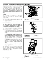
Fuse Block (Greensmaster 3320)
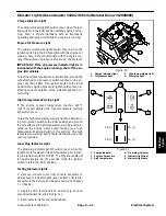
The fuse block on Greensmaster 3320 machines is at-
tached to the frame under the operator seat (Fig. 42).
Fuse Identification and Function
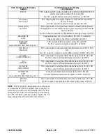
Use Figure 43 to identify each individual fuse and its cor-
rect amperage. Fuses for Greensmaster 3320 ma-
chines have the following function:
Right Fuse 1 (2 Amp):
Protects TEC logic and igni-
tion switch power supply circuits.
Right Fuse 2 (7.5 Amp):
Protects TEC output power
supply for start solenoid, charge circuit relay, kill
relay, fuel solenoid, optional leak detector (alarm and
indicator light) and console diagnostic light (if
equipped).
Right Fuse 3 (7.5 Amp):
Protects TEC output power
supply for cutting reels engage solenoid, lift enable
solenoid (S1), lift/lower solenoid (S2) and optional
hydraulic oil cooling fan relay.
Right Fuse 4 (7.5 Amp):
Protects TEC output power
supply for lift solenoids S3 (front cutting units) and S4
(center cutting unit).
Left Fuse 1 (10 Amp):
Protects power supply for
hour meter, low engine oil pressure indicator light (if
equipped), proximity switches (parking brake, neu-
tral and mow) and InfoCenter Display (if equipped).
Left Fuse 2 (15 Amp):
Protects power supply for op-
tional Turf Defender
TM
Leak Detector solenoid and
optional lights.
Left Fuse 3:
Not used.
Left Fuse 4 (15 Amp):
Protects power supply for op-
tional hydraulic oil cooling fan.
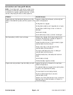
Fuse Testing
Make sure that ignition switch is OFF and key is re-
moved from switch. Remove fuses from the fuse block
for testing. Fuse should have continuity between fuse
terminals.
Figure 42
1. Seat base (raised)
2. Fuse block
1
2
Figure 43
RUN
LIGHTS
HYDRAULIC
FAN KIT
LIFT REEL
REEL ENGAGE
START/RUN
DIAG. LIGHT
TEC LOGIC
POWER
LEAK DE
TECTOR
LEAK DE
TECTOR
LIFT/LOWER
7.5A
7.5A
7.5A
2A
15A
10A
15A
RIGHT
4
3
2
1
LEFT
15A
15A
10A
7.5A
7.5A
7.5A
2A
Summary of Contents for Greensmaster 3420 TriFlex
Page 2: ...Greensmaster 3320 3420 This page is intentionally blank ...
Page 4: ...Greensmaster 3320 3420 This page is intentionally blank ...
Page 6: ...Greensmaster 3320 3420 This page is intentionally blank ...
Page 24: ...Greensmaster 3320 Page 3 6 Gasoline Engine This page is intentionally blank ...
Page 38: ...Greensmaster 3420 Page 4 4 Diesel Engine This page is intentionally blank ...
Page 54: ...Greensmaster 3420 Page 4 20 Diesel Engine This page is intentionally blank ...
Page 56: ...Greensmaster 3320 3420 Hydraulic System Page 5 2 This page is intentionally blank ...
Page 150: ...Greensmaster 3320 3420 Hydraulic System Page 5 96 This page is intentionally blank ...
Page 250: ...Greensmaster 3320 3420 Page 6 100 Electrical System This page is intentionally blank ...
Page 277: ...Greensmaster 3320 3420 Page 7 27 Chassis This page is intentionally blank Chassis ...
Page 325: ...Greensmaster 3320 3420 Groomer Page 9 13 This page is intentionally blank Groomer ...
Page 340: ...Greensmaster 3320 3420 Page 10 2 Foldout Drawings This page is intentionally blank ...
Page 347: ...Page 10 9 This page is intentionally blank ...
Page 356: ...Page 10 18 E Reels Wire Harness Drawing Greensmaster 3320 3420 Serial Number Below 312000000 ...
Page 358: ...Page 10 20 E Reels Wire Harness Drawing Greensmaster 3320 3420 Serial Number Above 312000000 ...
Page 360: ...Page 10 22 This page is intentionally blank ...

