Greensmaster 3320/3420
Page 6 -- 28
Electrical System
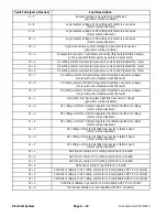
Hand Held Diagnostic Display
TEC Controller Inputs
Hand Held Diagnostic Display
LED Operation
JOYSTICK
LOWER
Joystick moved to lower (forward) position: LED ON
Joystick NOT moved to lower position: LED OFF
LEAK
DETECTOR (LD)
(Optional for Greensmaster 3320
machines only)
Leak detector switch closed (oil level is low): LED ON
Leak detector switch open (oil level is OK): LED OFF
ELECTRIC
REEL SPEED
Reel speed control (potentiometer) and circuit wiring OK: LED ON
Reel speed control (potentiometer) and circuit wiring faulty: LED OFF
HYD OIL
TEMP (DSL)
(Optional for Greensmaster 3420
machines only)
Hydraulic temperature, temp switch and circuit wiring OK: LED ON
Hydraulic temperature, temp switch or circuit wiring faulty: LED OFF
COOLANT
TEMP (DSL)
(Greensmaster 3420 machines only)
Engine coolant temperature has exceeded 220
o
F (105
o
C): LED ON
Engine coolant temperature below 220
o
F (105
o
C): LED OFF
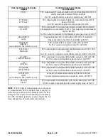
BACKLAP
Backlap switch in backlap position: LED ON
Backlap switch NOT in backlap position: LED OFF
PARKING
BRAKE (OFF)
Parking brake released: LED ON
Parking brake engaged: LED OFF
SEAT
SWITCH
Seat occupied: LED ON
Seat NOT occupied: LED OFF
JOYSTICK
RAISE
Joystick moved to raise (rear) position: LED ON
Joystick NOT moved to raise (rear) position: LED OFF
ALT FAULT
(DSL)
(Greensmaster 3420 machines only)
Engine not running OR alternator faulty: LED ON
Alternator OK: LED OFF
LOW ENGINE
OIL PRESSURE
Engine not running OR low engine oil pressure: LED ON
Engine oil pressure OK: LED OFF
NEUTRAL
SWITCH
Functional control lever in neutral: LED ON
Functional control lever in mow or transport: LED OFF
MOW
SWITCH
Functional control lever in mow: LED ON
Functional control lever in neutral or transport: LED OFF
KEY START
(NOTE: Place Functional Control Le-
ver in MOW or TRANSPORT so en-
gine will not start when turning ignition
switch to START)
Ignition switch in START: LED ON
Ignition switch in RUN: LED OFF
KEY
RUN
Ignition switch in RUN or START: LED ON
NOTE:
When the ignition switch is in the OFF position,
all Hand Held Diagnostic Display LED’s should be OFF.
NOTE:
The COOLANT TEMP (DSL) input can be simu-
lated by disconnecting the wire from the temperature
sender on the engine and then grounding the wire. The
appropriate input LED on the Diagnostic Display should
illuminate when the wire is grounded and the ignition
switch is in the ON position.
Summary of Contents for Greensmaster 3420 TriFlex
Page 2: ...Greensmaster 3320 3420 This page is intentionally blank ...
Page 4: ...Greensmaster 3320 3420 This page is intentionally blank ...
Page 6: ...Greensmaster 3320 3420 This page is intentionally blank ...
Page 24: ...Greensmaster 3320 Page 3 6 Gasoline Engine This page is intentionally blank ...
Page 38: ...Greensmaster 3420 Page 4 4 Diesel Engine This page is intentionally blank ...
Page 54: ...Greensmaster 3420 Page 4 20 Diesel Engine This page is intentionally blank ...
Page 56: ...Greensmaster 3320 3420 Hydraulic System Page 5 2 This page is intentionally blank ...
Page 150: ...Greensmaster 3320 3420 Hydraulic System Page 5 96 This page is intentionally blank ...
Page 250: ...Greensmaster 3320 3420 Page 6 100 Electrical System This page is intentionally blank ...
Page 277: ...Greensmaster 3320 3420 Page 7 27 Chassis This page is intentionally blank Chassis ...
Page 325: ...Greensmaster 3320 3420 Groomer Page 9 13 This page is intentionally blank Groomer ...
Page 340: ...Greensmaster 3320 3420 Page 10 2 Foldout Drawings This page is intentionally blank ...
Page 347: ...Page 10 9 This page is intentionally blank ...
Page 356: ...Page 10 18 E Reels Wire Harness Drawing Greensmaster 3320 3420 Serial Number Below 312000000 ...
Page 358: ...Page 10 20 E Reels Wire Harness Drawing Greensmaster 3320 3420 Serial Number Above 312000000 ...
Page 360: ...Page 10 22 This page is intentionally blank ...


